Abstract
We described the effect of fluorophore distance from the silver island films (SIFs) on the metal-enhanced fluorescence (MEF) from two newly developed long-chain nitrobenzoxadiazole derivatives (NBD-C16 and NBD-C18). The well-established Langmuir–Blodgett technique is used to deposit the fluorophores at defined distances from the SIFs surface, and an inert amphiphilic stearic acid is used to control the distance. NBD probes deposited directly on the SIFs surface show the highest metal-enhanced fluorescence of ~32-fold, and both of the probes that were studied show a consistent decrease in metal-enhanced fluorescence when increasing the distance from the fluorophore to the SIFs surface. The lowest fluorescence enhancement of ~4-fold is observed for the probes located 90 nm from the SIFs surface. Additionally, we also have noticed the shortest fluorescence lifetimes for the NBD probes deposited directly onto the SIFs surface, and the lifetimes are consistently increased when increasing the distances between the fluorophore and SIFs surfaces. These contrasting spectral changes, enhanced fluorescence, and decreased fluorescence lifetimes are in accordance with an increase in the rate of radiative decay for fluorophores near the silver particles. The present study provides significant information on the effect of fluorophore distance on the metal-enhanced fluorescence phenomenon.
1. Introduction
Noble metal nanoparticles and nanostructures have been the subjects of extensive theoretical and experimental studies.1–4 These particles exhibit unique and intense colors due to collective oscillations of electrons, which are known as plasmon absorption of metal particles.5,6 These resonating plasmons create local electromagnetic fields close to the particle surface. The intensity of the fields depends on the shape, size, and composition of the metal particle. The electromagnetic field intensity decreases with increasing distance from the metal particles. Accordingly, probe molecules located near metal particles experience varied electromagnetic field intensity, and thus the extent of metal–fluorophore interactions depends strongly on distance. Depending on the conditions, fluorophores near metallic particles show either quenching or an increase in fluorescence intensity.7,8 We refer to the latter observation as metal-enhanced fluorescence (MEF). This phenomenon can lead to important spectral changes such as a favorable increase in fluorescence intensity, photostability, and decreased lifetimes of the fluorophores.9–12 There is reasonable agreement that the maximum metal-enhanced fluorescence occurs when the probes are about 10 nm from the metallic structure, but some publications report an optimum distance of as large as 60 nm.13 At this time, there is limited information available on the effect of the fluorophore–metal distance on MEF. We recently addressed this issue, where we used alternating monolayers of biotinylated bovine serum albumin (BSA) and avidin-labeled DNA oligomers.14 We observed the highest fluorescence enhancement of 12-fold for a single BSA–avidin layer on silver island films (SIFs). The enhancement decreased to 2-fold when six biotin–avidin layers were used, where the fluorophore–metal distance was varied from ~10 to ~54 nm.14 Although these results provide a better understanding of the distance dependence of MEF, the spacing between the labeled oligo to the SIFs surface may not be precisely controlled. Protein conformational changes may lead to varying distances, especially with multiple BSA–avidin layers. Several other factors may contribute to the errors in the measured distance dependence. For example, the binding affinities of BSA to glass and SIF surfaces may not be the same. Hybridization of the labeled oligos to the surface-bound oligos may not be the same at all times, giving rise to varying dye concentrations on the layers. These experimental parameters need to be considered for a more quantitative understanding of the distance-dependent MEF phenomenon.
To improve the accuracy of the distance between the fluorophore and the surface, we used Langmuir–Blodgett (LB) films.15 The distances between the fluorophore monolayers and SIF surfaces were controlled using inert amphiphilic stearic acid (SA) layers. The distances between the probes and SIF surfaces are expected to be well controlled with the LB films. For example, the distance between the fluorophore and the SIF surface can be tailored by varying the number of inert SA layers, which provides a resolution of ~2.5 nm.15 Additionally, the LB technique is an established and valuable tool for the preparation of ultrathin films. In addition to controlling the monolayer thickness, the LB technique provides a homogeneous deposition of the monolayers over large areas and the possibility of fabricating multilayer structures with varying layer composition.15 The fluorophores deposited by the LB technique are expected to be at one distance rather than a range of distances from the metal surface or the metal island films. However, there will still be in-plane heterogeneity of fluorophores on or between the silver particles. Most importantly, unlike the situation with protein layers and subsequent hybridization, the probe orientation with respect to the surface normal is fixed and maintained in every monolayer irrespective of the distance from the surface.16,17 Hence, the LB technique offers not only a precise distance but also a well-defined orientation of the probe relative to the planar glass substrate.
We have prepared long-chain alkylamine-substituted nitrobenzoxadiazole (NBD) derivatives to use in MEF studies.18 These probes show an ~32-fold fluorescence enhancement and an ~5-fold decrease in the lifetime when LB monolayers of these probes were deposited directly onto the SIF surface. These contrasting spectral changes—an increase in fluorescence intensity and a decrease in lifetime—are in agreements with previous reports on MEF. In this article, we describe the effect of the distance between the NBD probes and the SIF surface on the MEF.
2. Experimental Details
2.1. Materials and Methods
The synthesis of long-chain alkylamine-substituted NBD derivatives—NBD-C16 [(4-hexadecylamino)-7-nitro-benz-2-oxa-1,3-diazole] and NBD-C18 [(4-octadecylamino)-7-nitro-benz-2-oxa-1,3-diazole]—was described elsewhere.18 The molecular structures of the probes are shown in Figure 1. Stearic acid (SA) and spectroscopic-grade chloroform were obtained from Aldrich and used without further purification. Distilled water, purified using a Millipore Milli-Q gradient system, was used for LB monolayer deposition and in all other chemical modifications. All other compounds, including silver nitrate, ammonium hydroxide, sodium hydroxide, and glucose were purchased from Sigma-Aldrich (St. Louis, MO) and used as received. The glass slides (Corning, NY) used for silver island film (SIF) preparation were first cleaned by soaking them for overnight in a 10:1 (v/v) mixture of H2SO4 (95–98%) and H2O2 (30%), commonly known as piranha solution. (Warning: piranha solution reacts strongly with organic compounds and should be handled with extreme caution. Do not store the solution in a closed container.) After washing vigorously with Milli-Q deionized water, the glass slides were air dried.
Figure 1.
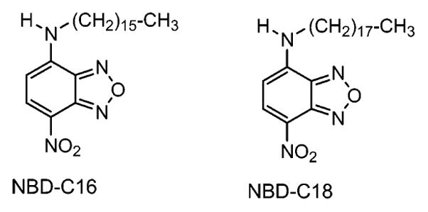
Molecular structures of the NBD probes.
2.2. Silver Island Film (SIF) Preparation
SIFs were deposited on clean glass slides using the method reported previously by us.10 Briefly, about 1.5 mL of freshly prepared 5% NaOH solution was added to a stirring aqueous silver nitrate solution (0.375 g in 45 mL water) in a glass beaker. Subsequently, the resulting dark-brown precipitate was redissolved by slowly adding 1 mL of NH4OH. The solution was cooled to 5 °C in an ice bath, and a fresh solution of D-glucose (0.540 g in 11 mL water) was added, followed by four pairs of dried glass slides placed in this solution. The mixture was stirred for 2 min in an ice bath and then allowed to warm up to 30 °C for the next 5 min. As the color of the mixture turned from yellow-green to yellow-brown, the color of the slides became green. The slides were removed from the beaker and rinsed with Milli-Q water. Excess and nonadhesive silver particles on the glass surface were removed by mild sonication of the SIF-coated glass slides for 1 min. As the result of using a sandwiched pair of glass slides for SIF formation, only one side of each slide was coated with silver islands. The SIF slides were stored in Milli-Q water until they were used for LB deposition. SIFs displayed the characteristic surface plasmon resonance with an absorption maximum near 460 nm.
2.3. LB Film Deposition
Depositions of LB films on glass and on SIF-coated glass are accomplished using a computer-controlled KSV 5000 LB trough. Milli-Q deionized water (pH ~5.8 at 20 °C with a resistivity of 18.2 MΩ cm) was used as the water subphase. Pure stearic acid monolayers on the water subphase were formed by spreading a known concentration of stearic acid in chloroform. On the basis of previous studies, we selected a particular monolayer composition for the present study.18 Accordingly, NBD-C16 or NBD-C18 and SA in a 1:3 molar ratio were dissolved in chloroform and used for monolayer preparation on the water subphase. After allowing for 15 min to evaporate the chloroform, the monolayer at the air–water interface was slowly compressed to a surface pressure of 20 mN/m. Subsequently, the compressed monolayer was transferred by the LB technique onto the solid substrates. A clean glass and SIF-coated glass slides were sandwiched together, and monolayers were deposited at a dipping speed of 5 mm/min. The initial layer on the surface was obtained during the upstroke. The observed monolayer transfer ratio from the compressed water subphase to the substrate was ~0.95. A schematic representation of LB layers on the surface is described in Figure 2. We first deposited an NBD-SA monolayer directly onto an SIF/glass surface to obtain a probe layer at 0 nm distance from the surface. Subsequently, to obtain the probes at defined distances from the surface we deposited the required number (i.e., 2, 4, 6, 14, or 36) of stearic acid layers followed by the probe layer (Figure 2B). Each stearic acid layer on surface provides a thickness of 2.5 nm. Subsequently, the use of 2, 4, 6, 14, and 36 layers of stearic acid results in probe distances (d) of 0, 5, 10, 15, 35, and 90 nm, respectively. In all mono- and multilayered LB films, the hydrophobic tail (alkyl chain) of the NBD probe’s exterior on the last layer is shown in Figure 2. The NBD probe has an orientation of about 68° from the surface normal, which we recently elucidated using polarized absorption spectroscopy.18
Figure 2.

Schematic representation of (A) a monolayer of NBD-Cx/SA deposited directly on glass and SIF surfaces and (B) a corresponding monolayer of the probes deposited on top of inert SA layers on glass and SIF surfaces. d is the distance between the fluorophore and SIF surface that can be varied with the number of inert SA layers at a resolution of ~2.5 nm.
2.4. Absorption and Fluorescence Spectroscopy
Absorption spectra were collected using a Hewlett-Packard 8453 spectrophotometer. Fluorescence spectra of monolayers on solid substrates were recorded using a Varian Cary Eclipse fluorescence spectrophotometer using front-face illumination geometry with 470 nm excitation from a xenon arc lamp. Time-resolved intensity decays were recorded using a PicoQuant Fluotime 100 time-correlated single-photon-counting (TCSPC) fluorescence lifetime spectrometer. The excitation at ~470 nm was obtained using a pulsed laser diode (PicoQuant PDL800-B) with a 20 MHz repetition rate. The instrument response function (IRF) is about 60 ps. The excitation was vertically polarized, and the emission was recorded through a polarizer oriented at 54.7° from the vertical position. A bandpass filter at 530–585 nm (Chroma Inc.) was used in the collection path, thus eliminating the scattered excitation light and collecting the fluorescence from the NBD probes in the region of interest.
2.5. Data Analysis
The fluorescence intensity decays were analyzed in terms of the multiexponential model as the sum of individual single-exponential decays:19
| (1) |
In this expression, τi represents the decay times, αi represents the amplitudes, and Σiαi = 1.0. The fractional contribution of each component to the steady-state intensity is described by
| (2) |
The average lifetime is represented by
| (3) |
The values of αi and τi were determined using PicoQuant Fluofit 3.3 software with the deconvolution of the instrument response function and nonlinear least-squares fitting. The goodness of fit was determined by the χ2 value.
3. Results and Discussion
3.1. Metal-Enhanced Fluorescence from NBD Monolayers on SIFs
The fluorescence emission spectra of a mixed monolayer of NBD-C18:SA at a molar ratio of 1:3 on glass and SIFs at the contact distance (i.e., 0 nm) from the surface are presented in Figure 3A. The mixed monolayer of NBD probes shows an emission band maximum at ~530 nm from both glass and SIF surfaces. Figure 3 (inset) shows the intensity-normalized emission spectra of the probes obtained from both metalized and nonmetalized areas, which completely overlap with each other. A significant enhancement (of ~32-fold) in fluorescence intensity is observed from NBD monolayers on SIFs as compared to those on the glass surface (Figure 3). The enhancement can be defined as the ratio of integrated intensities detected on SIFs and glass substrates in the 500–700 nm spectral range. The fluorescence spectra were collected under the same excitation and detection conditions, allowing a direct comparison between the two substrates. The observed fluorescence enhancement from NBD monolayers deposited on SIFs seems surprising considering the usual expectation of fluorescence quenching when probes are placed directly on a metal surface. Normally, an ~10 nm spacer layer is suggested to avoid quenching.12,13 Additionally, we found only a 3-fold enhancement when the probe is spin coated on a SIF surface (data not shown).18 Although we are not certain about the exact reason for the high MEF of 32-fold from the LB monolayer, we suggest that the LB deposition provides a controlled orientation of the probe molecules for favorable interaction with the silver particles. Overall, it seems surprising that the largest enhancement was observed when the fluorophore was placed directly on the SIFs.
Figure 3.
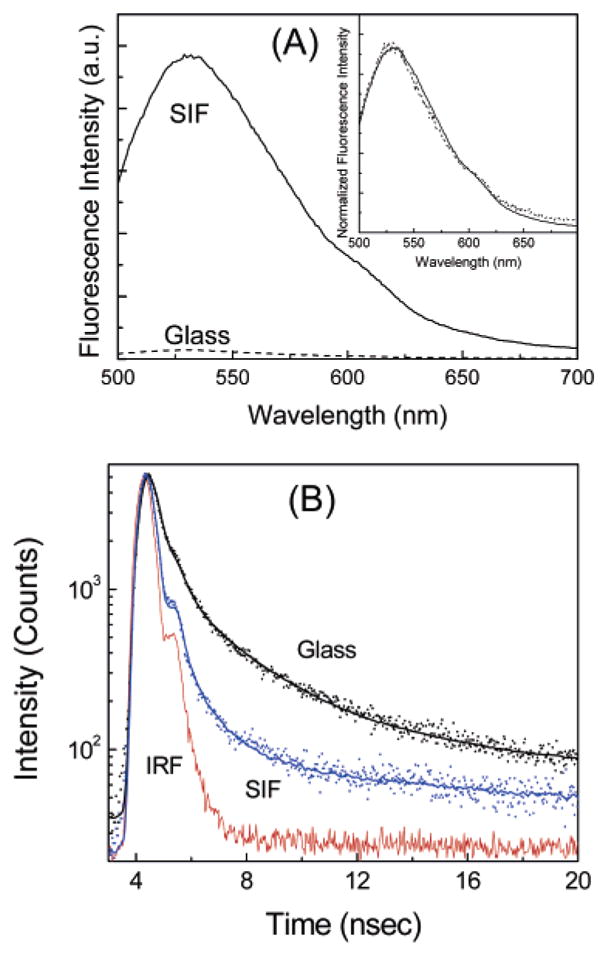
(A) Emission spectra of NBD-C18/SA monolayers on glass and SIF surfaces. The inset shows the corresponding intensity-normalized emission spectra. (B) Fluorescence intensity decays of monolayers of NBD-C18/SA on glass and SIFs. The instrument response function (IRF) is also included.
We also measured the effects of SIFs on the NBD probe using time-correlated single-photon counting (TCSPC). The intensity decays observed for the NBD-C18/SA (1:3) on glass and a SIF are shown in Figure 3B. Also shown in the Figure is the instrument response function. The solid lines indicate the best multiexponential fit to the experimental decay curves. A very similar decay was observed for the NBD-C16/SA (1:3) mixed monolayer. As can be seen in the Figure, the intensity decay of NBD monolayers on SIFs are faster than those on glass substrate. The fluorescence lifetime of NBD derivatives is significantly shortened (~5-fold) when the monolayers are on SIFs. This shortening of the lifetime on SIFs strongly indicated that the increase in fluorescence intensity is due to fluorophore interactions with the silver nanoparticles.9–12 Metallic colloids are known to scatter strongly.5,6,20 We verified that the short component in the intensity decay is not due to scattered light. Control measurements on the glass or SIF substrates, without NBD derivatives, yielded almost no signal when observed through the combination of filters used to isolate the NBD emission. We further examined the possibility of scattered light by recording the emission spectra through the emission filter sets used for the intensity–time decay measurements. These experiments showed no detectable intensity with an excitation wavelength of 470 nm, demonstrating that scattered light is not the origin of the short-lifetime components of NBD derivatives on SIFs.
The effect of metal particles on the emission of fluorophores is dependent on at least two factors:9–13 an enhanced local field and an increase in the intrinsic decay rate of the fluorophore. The first factor provides stronger excitation rates. The second factor changes the quantum yield and lifetime of the fluorophore. The increase in the local field results in a higher excitation rate but does not modify the fluorescence lifetime of the molecules.12
The simultaneous increase in quantum efficiency and decrease in lifetime indicates an increased radiative decay rate in the presence of silver particles.12 The quantum yield and lifetime of a fluorophore are interrelated by
| (4) |
| (5) |
where Γ and knr are the radiative and nonradiative decay rates, respectively. In the presence of metal, the quantum yield and lifetime are given by
| (6) |
| (7) |
In the presence of metal, the radiative decay rate is increased to NrΓ and knr′ is the nonradiative rate. The modification of knr by metal is assumed to be negligible (knr ≈ knr′).12
3.2. Effect of Distance on Metal-Enhanced Fluorescence
Fluorescence emission spectra from NBD-C18/SA monolayers at varying distances from the SIFs are shown in Figure 4A. The highest MEF enhancement of 32-fold is seen for the monolayer within contact distance (0 nm) of the SIF surface. The enhancement decreases monotonically upon increasing the distance from 0 to 90 nm. Figure 4B shows the fluorescence enhancement factor relative to glass with respect to the distance between the probe monolayer and SIF surface. As can be seen from the Figure, both NBD-C16/SA and NBD-C18/SA show very similar distance dependences for the enhancement.
Figure 4.
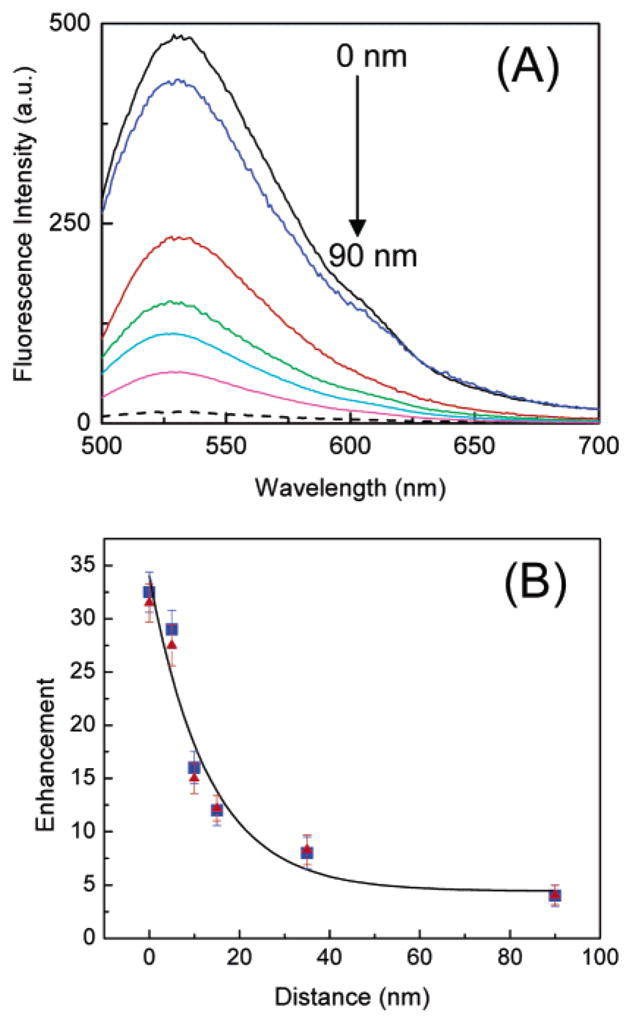
(A) Emission spectra of NBD-C18/SA LB monolayers deposited various distances from the SIF surface. Fluorescence spectra of NBD-C18/SA on a glass surface is also included (- -). (B) Fluorescence enhancement factor relative to the glass for NBD-C16 (▲) and NBD-C18 (■) probes as a function of monolayer distance from the SIF surfaces.
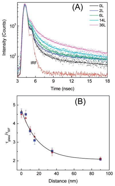
We measured the fluorescence intensity decays for all NBD monolayers on SIFs and the glass surface. Figure 5 shows the fluorescence intensity decays of NBD-C18/SA on the surfaces. Interestingly, the intensity decay of the probes on SIFs at 0 nm distance shows the shortest decay time. The average lifetime increased monotonically with increasing distance from the SIF surface. Within experimental error, the corresponding fluorescence intensity decays of the probes deposited any distance from the glass surface show very similar lifetimes. A representative intensity decay of monolayer on glass is shown in Figure 3B. The ratios of the average lifetimes of each particular layer on SIFs and glass are plotted as a function of the distance from the SIF surface. The fluorescence lifetime reduction for the monolayer deposited directly on a SIF versus glass is about 5-fold and decreases to ~2-fold when the probes are separated by 90 nm. Both NBD-C16/SA and NBD-C18/SA show very similar fluorescence intensity decays.
Figure 5.
(A) Fluorescence intensity decays of NBD-C18/SA monolayers on SIF surfaces at various distances. The dots and the lines represent the data and multiexponential fits, respectively. The lower solid line is the impulse response function (IRF) for the instrument. The inserted number represents the number of stearic acid layers as spacers. (B) Distance dependence of emission lifetimes of NBD-C16 (▲) and NBD-C18 (■) probes at varying distances from the SIF surface.
The effects of silver nanoparticles on the quantum yields and radiative decay rates of fluorophores can be described by eqs 4–7. In this section, we analyzed our steady-state and time-resolved fluorescence data (Figures 4 and 5) in terms of a phenomenological model based on eqs 4–7 that accounts for the expected interactions. These interactions are an increase in the radiative decay rate (Γ) by a factor of Nr and an increase in the rate of excitation by a factor of Nex. The increases in the rates of emission and excitation depend on the distance (d) between the metal and fluorophore and can be described14 by
| (8) |
| (9) |
where Rr and Rex are the characteristics distances over which these effects decrease to 1/e exponentially. Combining eqs 5, 7, and 8, the ratio of the fluorescence lifetimes of the probes on the SIF and glass surfaces with respect to the fluorophore-to-surface distance (d) is given by
| (10) |
The total fluorescence intensity in the presence of metal (Im) as a function of metal–fluorophore distance d is described by
| (11) |
where I0 is the measured intensity in the absence of metal. In terms of τm and τ0, eq 11 can be rewritten as
| (12) |
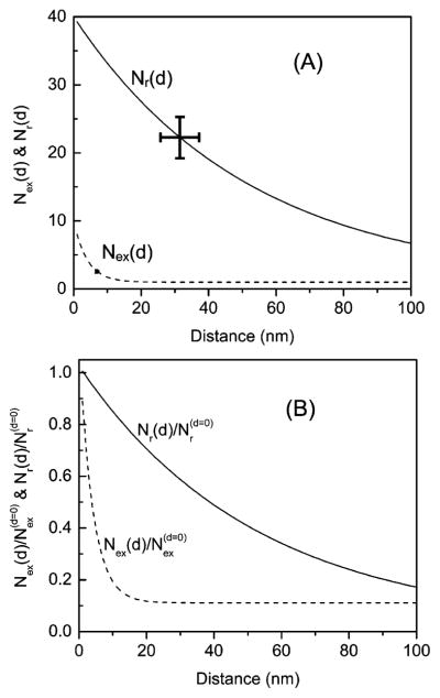
Using eq 12, we have fitted our intensity and lifetime data considering , Rr, and Rex to be free parameters. These free parameters were evaluated by fitting the experimental data using Levenberg–Marquardt iterations. The fitting yields values of 39, 9, 52, and 4 nm for , Rr, and Rex, respectively. The nonradiative decay rate is also extracted from the fitting. Accordingly, we have obtained a knr′ value of 3 × 10⁹ s−1, which agrees well with the reported literature value for structurally similar NBD derivatives.21
These results indicate that the rate of excitation is increased 9-fold at the shortest distances and that this effect is relatively short-ranged over about 4 nm. In contrast, the radiative decay rate appears to be increased 39-fold, and this effect occurs over longer distances of ~52 nm. We questioned how these calculated values could be affected by errors in the measured spectral parameters. In particular, it seemed possible that a very short lifetime component (especially the lifetimes of the probes on the SIFs surfaces) could be missed in the time-domain measurements. Accordingly, we reanalyzed the data assuming that the lifetimes on SIFs surfaces were 2-fold shorter than the measured values. This calculation yielded values of 78, 9, 55, and 4 nm for , Rr, and Rex, respectively, which indicate that , Rr, and Rex are less sensitive to errors in the measured lifetimes. However, the rate of radiative decay is increased by the same factor of 2.
Figure 6 shows the changes in the radiative decay rate (Nr) and the rate of excitation (Nex) with respect to the distance between the fluorophore and SIF surfaces. It can be understood from the Figure that the increase in the radiative rate (Nr) on SIF surface decreases with increased distances over 50 nm. A substantial increase in the rate of excitation (Nex) occurs below 10 nm. These results are in good agreement with the previous report.14
Figure 6.
(A) Changes in the rate of excitation Nex(d) and radiative decay rate Nr(d) of NBD probes as a function of the distance from the SIF surfaces. Curves are generated from the measured spectral parameters using eqs 8 and 9 for (B) and as a function of the distance from the SIF surface.
4. Summary
The distance dependence on metal-enhanced fluorescence is studied using two long-chain alkylamino-substituted NBD derivatives. The probes were deposited using the Langmuir–Blodgett technique at varied distances from the SIFs or glass surfaces. Inert stearic acid layers are used to control the distance. A maximum enhancement of 32-fold is observed with contact distances from the SIF surfaces. The enhancement is reduced to 4-fold when the probe is separated by 90 nm stearic acid layers. The corresponding fluorescence intensity decays show increased average lifetimes upon increasing the distance. The data in this article provides information on the distance dependence of fluorophore–metal interactions that governs metal-enhanced fluorescence.
Acknowledgments
This work was supported by the National Institutes of Health (NIH) (RR-08119 and EB-00682) and the National Science Foundation (NSF) BES0517785.
References
- 1.Kreibig U, Vollmer M. Optical Properties of Metal Clusters, Springer Series in Material Science. Vol. 25 Springer; Berlin: 1995. [Google Scholar]
- 2.Bohren CF, Huffman DR. Absorption and Scattering of Light by Small Particles. Wiley; New York: 1983. [Google Scholar]
- 3.Otto A, Mrozek I, Grabhorn H, Akemann A. J Phys: Condens Matter. 1992;4:1143. [Google Scholar]
- 4.Barnes WL. J Mod Opt. 1995;45:661. [Google Scholar]
- 5.Yguerabide J, Yguerabide EE. Anal Biochem. 1998;262:137–156. doi: 10.1006/abio.1998.2759. [DOI] [PubMed] [Google Scholar]
- 6.Yguerabide J, Yguerabide EE. Anal Biochem. 1998;262:157–176. doi: 10.1006/abio.1998.2760. [DOI] [PubMed] [Google Scholar]
- 7.Drexhage KH. J Lumin. 1970;1–2:693–701. [Google Scholar]
- 8.Drexhage KH. In: Progress in Optics XII. Wolf E, editor. North-Holland: Amsterdam; 1974. p. 165. [Google Scholar]
- 9.Lakowicz JR. Anal Biochem. 2001;298:1–24. doi: 10.1006/abio.2001.5377. [DOI] [PMC free article] [PubMed] [Google Scholar]
- 10.Lakowicz JR, Shen Y, D’Auria S, Malicka J, Fang J, Grcyzynski Z, Gryczynski I. Anal Biochem. 2002;301:261–277. doi: 10.1006/abio.2001.5503. [DOI] [PMC free article] [PubMed] [Google Scholar]
- 11.Lakowicz JR. Anal Biochem. 2004;324:153–169. doi: 10.1016/j.ab.2003.09.039. [DOI] [PMC free article] [PubMed] [Google Scholar]
- 12.Lakowicz JR. Anal Biochem. 2005;337:171–194. doi: 10.1016/j.ab.2004.11.026. [DOI] [PMC free article] [PubMed] [Google Scholar]
- 13.Sokolov K, Chumanov G, Cotton TM. Anal Chem. 1998;70:3898–3905. doi: 10.1021/ac9712310. [DOI] [PubMed] [Google Scholar]
- 14.Malicka J, Gryczynski I, Gryczynski Z, Lakowicz JR. Anal Biochem. 2003;315:57–66. doi: 10.1016/S0003-2697(02)00702-9. [DOI] [PMC free article] [PubMed] [Google Scholar]
- 15.Ulman A. An Introduction to Ultrathin Organic Films: From Langmuir-Blodgett to Self-Assembly. Academic Press; San Diego, CA: 1991. [Google Scholar]
- 16.Ray K, Nakahara H. J Phys Chem B. 2002;106:92–100. [Google Scholar]
- 17.Ray K, Nakahara H. Phys Chem Chem Phys. 2001;3:4784–4790. [Google Scholar]
- 18.Ray K, Badugu R, Lakowicz JR. J Phys Chem B. 2006;110:13499–13507. doi: 10.1021/jp0620623. [DOI] [PMC free article] [PubMed] [Google Scholar]
- 19.Lakowicz JR. Principles of Fluorescence Spectroscopy. 2. Kluwer Academic/Plenum Publishers; New York: 1999. [Google Scholar]
- 20.Schultz S, Smith DR, Mock JJ, Schultz DA. Proc Natl Acad Sci USA. 2000;97:996–1001. doi: 10.1073/pnas.97.3.996. [DOI] [PMC free article] [PubMed] [Google Scholar]
- 21.Saha S, Samanta A. J Phys Chem A. 1998;102:7903–7912. [Google Scholar]


