

Abstract
Roughened silver electrodes are widely used for surface-enhanced Raman scattering (SERS). We tested roughened silver electrodes for metal-enhanced fluorescence. Constant current between two silver electrodes in pure water resulted in the growth of fractal-like structures on the cathode. This electrode was coated with a monolayer of human serum albumin (HSA) protein that had been labeled with a fluorescent dye, indocyanine green (ICG). The fluorescence intensity of ICG–HSA on the roughened electrode increased by ≈50-fold relative to the unroughened electrode, which was essentially non-fluorescent and increased typically two-fold as compared to the silver anode. No fractal-like structures were observed on the anode. Lifetime measurements showed that at least part of the increased intensity was due to an increased radiative decay rate of ICG.
In our opinion, the use of in situ generated roughened silver electrodes will find multifarious applications in analytical chemistry, such as in fluorescence based assays, in an analogous manner to the now widespread use of SERS. To the best of our knowledge this is the first report of roughened silver electrodes for metal-enhanced fluorescence.
Keywords: Roughened silver electrodes, Metal-enhanced fluorescence, Surface-enhanced Raman scattering
1. Introduction
Raman spectroscopy is known for its low signal intensities. Surprisingly, Raman spectroscopy is now finding use in biological research, intracellular analysis and genomics [1–3]. This remarkable development has its origins in 1974 with the report of an enormous enhancement of the scattered intensity for pyridine adsorbed to roughened silver electrodes. These surfaces are prepared from silver by sweeping the voltage between the electrodes by plus or minus fractions of a volt for several minutes in the presence of KCl [4,5].
Since these initial observations of surface-enhanced Raman scattering (SERS) there have been extensive theoretical and experimental studies of these effects. The enhanced SERS signal has been explained as due to an electromagnetic interaction between the incident light, sub-wavelength size silver particles and the organic molecule [6,7]. The increased Raman intensities using silver particles are so large that SERS from single molecules has become detectable [3,8]. It is now thought that these highly active SERS sites are favorably positioned between two or more particles [9,10]. An electromagnetic interaction certainly contributes to the SERS intensity, but part of the enhancement may be due to chemical interactions of the adsorbed molecule with the surface.
While the theory has focused on SERS, it was recognized that these interactions can also affect fluorescence [11–14]. Such interactions were first demonstrated by Drexhage who found effects of mirrors on lifetimes [15]. These interactions have been used in some early reports of metal-enhanced fluorescence [16,17].
During the past 2 years we have focused our efforts on understanding the interactions of fluorophores with metallic particles. We found that proximity to metallic surfaces can increase fluorescence intensities and quantum yields, decrease lifetimes and increase photostability [18–20]. These studies used silver island films, which are formed by the chemical reduction of silver nitrate onto a glass surface. In the present report, we questioned whether these favorable effects would also occur on roughened silver electrodes. For these studies we used indocyanine green (ICG, Fig. 1) because of its widespread use in medical testing and imaging [21–25]. ICG spontaneously binds to human serum albumin (HSA), which is probably its form following medical injection into blood [26]. A favorable property of this system is that HSA adsorbs to form a monolayer on glass and silver [27].
Fig. 1.
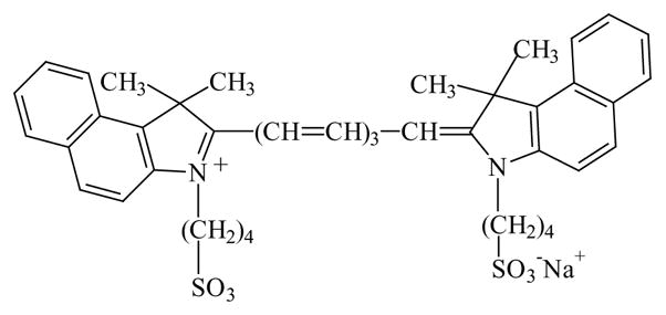
Chemical structure of ICG.
2. Experimental materials
ICG and HSA were obtained from Sigma, and used without further purification. Concentrations of ICG and HSA were determined using extinction coefficients of ε 780 nm) = 130,000 cm−1 and ε (278 nm) = 37,000 cm−1, respectively.
Glass slides (Aldrich) were cleaned before use by immersion in 30% (v/v) H2O2 and 70% (v/v) H2SO4 for 48 h and were then washed in distilled water. The glass slides were then used to sandwich the roughened silvered electrodes so as to keep the surfaces wet.
The silver electrodes (Aldrich) had dimensions of 9 mm × 35 mm × 0.1 mm. A constant current generator circuit (Fig. 2) was used to supply 60 μA across the two electrodes for 10 min. The electrodes were separated by ≈10 mm. The space between the electrodes was filled with distilled water.
Fig. 2.

Constant current circuit.
Binding the ICG–HSA to the both the silver anode and cathode after electrolysis, was accomplished by soaking the electrodes in a 30 μM ICG, 60 μM HSA solution overnight, followed by rinsing with water to remove the unbound material. As a control sample, an unused silver electrode was also coated with ICG–HSA.
A roughened silver cathode was also dipped in 10−4 M NaCl for 1 h before being washed and then coated with ICG–HSA, so as to place our findings in context with the huge enhancements in Raman signals, typically obtained after chloride dipping the electrodes [4,5].
3. Methods
Excitation and observation of the electrodes were made by the front face configuration (Fig. 3). Steady-state emission spectra were recorded using a SLM 8000 spectrofluorometer with excitation using a Spectra Physics Tsunami Ti: Sapphire laser in the CW (non-pulsed) mode which was attenuated as required ≈200 mW 760 nm output.
Fig. 3.
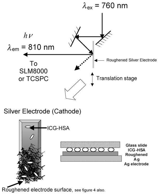
Experimental geometry.
Time-resolved intensity decays were measured using reverse start–stop time-correlated single-photon counting. Vertically polarized excitation at ≈760 nm was obtained using a mode-locked argon-ion pumped, cavity dumped Pyridine 2 dye laser with a 3.77 MHz repetition rate. The instrumental response function, determined using the experimental geometry in Fig. 3 and a glass microscope slide, was typically <50 ps FWHM. The emission was collected at the magic angle (54.7°), using a long pass filter (Edmund Scientific), which cut-off wavelengths below 830 nm. This had the effect of showing ICG emission spectra with emission maxima at ≈830 nm instead of the solution maxima centered near 800 nm. This filter was necessary so as to discriminate against a highly scattering (reflective) background.
4. Data analysis
The intensity decays were analyzed in terms of the multi-exponential model:
| (1) |
where αi are the amplitudes and τi the decay times, Σαi = 1.0. The fractional contribution of each component to the steady-state intensity is given by:
| (2) |
The mean lifetime of the excited state is given by:
| (3) |
and the amplitude-weighted lifetime is given by:
| (4) |
The values of αi and τi were determined by non-linear least squares impulse reconvolution with a goodness-of-fit criterion.
5. Results
We visually examined the silver electrodes using bright field microscopy during current flow. We observed a rapid growth of fractal-like structures on the cathode (Fig. 4). These structures are visually similar to those recently found during silver deposition onto an insulator [28]. We incubated the cathode and anode with ICG–HSA, allowing the labeled proteins to bind to the silver surfaces. Essentially no emission was seen from ICG–HSA on an unroughened bright silver surface (Ag in Fig. 5). However, a dramatically large signal was observed on the roughened cathode and a somewhat smaller signal was observed on the anode. In all our experiments, we typically found that the roughened silver cathode was ≈20–100-fold more fluorescent than the unroughened control Ag electrode. In comparison, the anode was typically 5–50 times more fluorescent than the Ag control. When we increased the time-for-roughening to over 1 h, the intensities of both electrodes after coating with ICG–HSA were essentially indistinguishable, but still ≈50-fold more fluorescent than the unroughened Ag control. The emission spectra on the two electrodes probably had the same emission maximum. The shift seen in Fig. 5 (bottom) is thought to be due to the filters used to reject the scattered light.
Fig. 4.

Silver growth on the silver cathode as a function of time, visualized using transmitted light. This growth structure was characteristic of the whole electrode.
Fig. 5.

(Top) Fluorescence intensity of HSA–ICG coated roughened silver electrodes and an unused silver electrode, Ag, Ex = 760 nm. (Bottom) Fluorescence intensities normalized to the intensity of the ICG–HSA coated silver cathode. It should be noted that the normal fluorescence emission maximum (H2O, pH 7) of 810 nm is shifted in this regard due to the choice of filters than were required to discriminate against a highly scattering surface.
The increased intensities seen in Fig. 5 could have several explanations. Two possibilities are increased excitation rates due to the enhanced incident fields around the metal particles and/or increased amounts of protein bound to the fractal surface, i.e. a greater surface area. For both mechanisms the fluorescence lifetimes are expected to remain the same. We also examined the intensity decay of ICG–HSA in buffers. ICG–HSA on the control silver electrode was not measurable due to the very low fluorescence signal intensity. In buffer the amplitude-weighted lifetime of ICG–HSA was found to be 0.55 ns (Table 1).
Table 1.
Analysis of the intensity decay of ICG–HSA measured using the reverse start–stop time-correlated single photon counting technique and the multi-exponential model
| Sample | αi | τi (ns) | fi | τ̄ (ns) | <τ> (ns) | ||
|---|---|---|---|---|---|---|---|
| In buffer | 0.158 | 0.190 | 0.05 | – | – | ||
| 0.842 | 0.615 | 0.95 | 0.592 | 0.548 | 1.4 | ||
| a Ag cathode | 1.0 | <0.010 | 1.0 | <0.010 | <0.010 | – |
The roughened Ag cathode had ICG lifetimes <10 ps. With the time-resolution of the system ≈50 ps FWHM, the discrete lifetimes could not be so easily obtained.
We next examined the intensity decay of ICG–HSA on the cathode (Fig. 6). In this case, the lifetimes were dramatically shortened to <10 ps, in fact so short, that it was difficult to determine the absolute values with a system time resolution of ≈50 ps FWHM. However, a decreased lifetime with an increased fluorescence intensity, strongly suggests an increase in the radiative decay rate of the fluorophores [18]. In all our control experiments scattered light was alleviated.
Fig. 6.
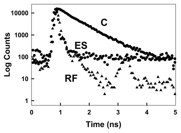
Complex intensity decays of ICG–HSA in a cuvette (buffer), C, and on a roughed silver electrode, ES. RF, instrumental response function.
ICG is well-known to rapidly degrade in solution due to chemical and/or photochemical processes. The observed 50–100-fold increases in fluorescence intensity of ICG–HSA seen in Fig. 5 would not be analytically useful if the sample degraded 50–100 times faster. We subsequently examined the steady-state intensity of ICG–HSA with continuous illumination (Fig. 7). At the onset of illumination the relative intensity of ICG–HSA decays more rapidly on the fractal structure than on the control sample (Fig. 7 (top)). However, the effect is small and rates become comparable after 2 min. Interestingly, if the illumination intensity is adjusted so that both samples yield the same steady-state emission intensity at the onset of illumination, then the ICG–HSA on the fractal-like silver cathode photobleaches at a much slower rate (Fig. 7 (bottom)). Given that the detectable signal from the ICG–HSA is given by the area under these photobleaching curves, then substantially more emission can be obtained from the roughened electrodes as compared to the control sample. Intuitively, the ICG intensity remains higher even after the initial decrease in intensity, (Fig. 7 (top)), which suggests that ICG will display higher intensities for longer times when bound to fractal silver electrodes. Such effects are most desirable in many analytical applications such as in high-sensitivity surface assays.
Fig. 7.

(Top) Photostability of ICG–HSA on a roughened silver electrode and on an unused silver electrode, measured using the same excitation power at 760 nm and (bottom) with the laser power adjusted to give the same initial fluorescence intensities. In all measurements, vertically polarized excitation was used, whilst fluorescence emission was observed at the magic angle, i.e. 54.70°. It should be noted there is a background of about 40 cps which has not been subtracted in these intensity plots.
Finally, to place our work in context with the analytical use of roughened silver electrodes in SERS, we dipped our roughened silver cathode in 10−4 M chloride for 1 h before coating with ICG–HSA. Such a treatment of the electrode typically results in significantly large enhancements in the surface Raman intensities [4,5]. We questioned what would be observed for the fluorescence intensities? Fig. 8 shows the fluorescence intensity of ICG–HSA coated roughened silver electrode and a chloride dipped silver electrode under otherwise identical conditions. We generally observed a decrease in the maximum fluorescence intensity of the chloride-dipped electrode as compared to the non-chloride roughened silver electrode. However, the ICG–HSA emission on the chloride-dipped electrode was substantially more fluorescent than on the unroughened electrode. These results, therefore, suggest that the chloride treatment of the electrodes has no obvious effect on metal-enhanced fluorescence. Our results, therefore, support current thinking in that SERS is a consequence of surface (near-surface) interactions as compared to metal-enhanced fluorescence, which is considered to be a through-space phenomenon [18].
Fig. 8.

(Top) Fluorescence intensity of HSA–ICG coated roughened silver electrode and a chloride dipped silver electrode, Ag, Ex = 760 nm. (Bottom) Fluorescence intensities normalized to the intensity of the ICG–HSA coated silver cathode (no chloride). It should be noted that the normal fluorescence emission maximum (H2O, pH 7) of 810 nm is shifted in this regard due to the choice of filters than were required to discriminate against a highly scattering surface.
6. Discussion
In the previous manuscripts, we showed that silver particles formed by chemical reduction were effective in increasing fluorescence [18–20,29]. We also have shown that silver deposited by laser irradiation of a solution of silver nitrate can also enhance fluorescence [30]. The present observation of enhanced fluorescence on roughened silver electrodes indicates that a variety of methods can now be used to form particulate silver, which retains its enhancing properties. This versatility can be useful in the many envisaged analytical applications of metal-enhanced fluorescence, such as in microfluidic and lab-on-a-chip based sensing [31–33].
Acknowledgments
This work was supported by the National Institute of Biomedical Imaging and Bioengineering NIH EB-00682 and the National Center for Research Resource, RR-08119.
References
- 1.Kneipp K, Kneipp H, Itzkan I, Dasari RR, Feld MS. Curr Sci. 1999;77(7):915–924. [Google Scholar]
- 2.Vo-Dinh T, Stokes DL, Griffin GD, Volkan M, Kim UJ, Simon MI. J Raman Spectrosc. 1999;30:785–793. [Google Scholar]
- 3.Kneipp K, Kneipp H, Kartha B, Manoharan R, Deinum G, Itzkan I, Dasari RR, Feld MS. Phys Rev E. 1998;57(6):R6281–R6284. [Google Scholar]
- 4.Fleischmann M, Hendra PJ, McQuillan AJ. Chem Phys Letts. 1974;26(2):163–166. [Google Scholar]
- 5.Roth E, Hope GA, Schweinsberg DP, Kiefer W, Fredericks PM. Appl Spectrosc. 1993;47(11):1794–1800. [Google Scholar]
- 6.Gersten J, Nitzan A. J Chem Phys. 1981;75(3):1139–1152. [Google Scholar]
- 7.Weitz DA, Garoff S, Gersten JI, Nitzan A. J Chem Phys. 1983;78(9):5324–5338. [Google Scholar]
- 8.Nie S, Emory SR. Science. 1997;275:1102–1106. doi: 10.1126/science.275.5303.1102. [DOI] [PubMed] [Google Scholar]
- 9.Michaels AM, Jiang J, Brus L. J Phys Chem B. 2000;104:11965–11971. [Google Scholar]
- 10.Michaels AM, Nirmal M, Brus LE. J Am Chem Soc. 1999;121:9932–9939. [Google Scholar]
- 11.Kummerlen J, Leitner A, Brunner H, Aussenegg FR, Wokaun A. Mol Phys. 1993;80(5):1031–1046. [Google Scholar]
- 12.Weitz DA, Garoff S, Hanson CD, Gramila TJ. Opt Letts. 1982;7(2):89–91. doi: 10.1364/ol.7.000089. [DOI] [PubMed] [Google Scholar]
- 13.Barnes WL. J Modern Opt. 1998;45(4):661–699. [Google Scholar]
- 14.Aussenegg FR, Leitner A, Lippitsch ME, Reinisch H, Reigler M. Surf Sci. 1987;139:935–945. [Google Scholar]
- 15.Drexhage KH. Interaction of light with monomolecular dye lasers. In: Wolfe E, editor. Progress in Optics. North-Holland Publishing Company; Amsterdam: 1974. pp. 161–232. [Google Scholar]
- 16.Schalkhammer T, Aussenegg FR, Leitner A, Brunner H, Hawa G, Lobmaier C, Pittner F. SPIE. 1997;2976:129–136. [Google Scholar]
- 17.Mayer C, Stich N, Schalkhammer TGM. SPIE. 2001;4252:37–46. [Google Scholar]
- 18.Lakowicz JR. Anal Biochem. 2001;298:1–24. doi: 10.1006/abio.2001.5377. [DOI] [PMC free article] [PubMed] [Google Scholar]
- 19.Lakowicz JR, Shen B, Gryczynski Z, D’Auria S, Gryczynski I. Biochem Biophys Res Commun. 2001;286:875–879. doi: 10.1006/bbrc.2001.5445. [DOI] [PMC free article] [PubMed] [Google Scholar]
- 20.Lakowicz JR, Shen Y, D’Auria S, Malicka J, Fang J, Gryczynski Z, Gryczynski I. Anal Biochem. 2002;301:261–277. doi: 10.1006/abio.2001.5503. [DOI] [PMC free article] [PubMed] [Google Scholar]
- 21.Henschen S, Busse MW, Zisowsky S, Panning B. J Med. 1993;24(1):10–27. [PubMed] [Google Scholar]
- 22.Ott P, Keiding S, Johnsen AH, Bass L. Am J Physiol. 1994;266:G1108. doi: 10.1152/ajpgi.1994.266.6.G1108. (Gastrointest. Liver Physiol. 29 (1994)) [DOI] [PubMed] [Google Scholar]
- 23.Sakka SG, Reinhart K, Wegscheider K, Meier-Hellmann A. Chest. 2002;121(2):559–565. doi: 10.1378/chest.121.2.559. [DOI] [PubMed] [Google Scholar]
- 24.Flower RW. Am J Ophalmol. 2000;129(4):501–512. doi: 10.1016/s0002-9394(99)00411-0. [DOI] [PubMed] [Google Scholar]
- 25.Flower RW, Von Kerczek C, Zhu L, Ernest A, Eggleton C, Topoleski LDT. Am J Opthalmol. 2001;132(1):85–93. doi: 10.1016/s0002-9394(01)00872-8. [DOI] [PubMed] [Google Scholar]
- 26.Devoisselle JM, Soulie S, Maillois H, Desmettre T, Mordon S. SPIE. 1997;2980:293–302. [Google Scholar]
- 27.Sokolov K, Chumanov G, Cotton TM. Anal Chem. 1998;70:3898–3905. doi: 10.1021/ac9712310. [DOI] [PubMed] [Google Scholar]
- 28.Fleury V, Watters WA, Allam L, Devers T. Nature. 2002;416:716–719. doi: 10.1038/416716a. [DOI] [PubMed] [Google Scholar]
- 29.Geddes CD, Cao H, Gryczynski I, Gryczynski K, Lakowicz JR. J Phys Chem A. 2003;107:3443–3449. doi: 10.1021/jp022040q. [DOI] [PMC free article] [PubMed] [Google Scholar]
- 30.Geddes CD, Parfenov A, Lakowicz JR. Appl Spectrosc. 2003;57(5):526–531. doi: 10.1366/000370203321666542. [DOI] [PMC free article] [PubMed] [Google Scholar]
- 31.Christodoulides N, Tran M, Floriano PN, Rodriguez M, Goodey A, Ali M, Neikirk D, McDevitt JT. Anal Chem. 2002;74:3030–3036. doi: 10.1021/ac011150a. [DOI] [PubMed] [Google Scholar]
- 32.Verpoorte E. Electrophoresis. 2002;23:677–712. doi: 10.1002/1522-2683(200203)23:5<677::AID-ELPS677>3.0.CO;2-8. [DOI] [PubMed] [Google Scholar]
- 33.Keir R, Igata E, Arundell M, Smith WE, Graham D, McHugh C, Cooper JM. Anal Chem. 2002;74(7):1503–1508. doi: 10.1021/ac015625+. [DOI] [PubMed] [Google Scholar]