

Abstract
In reports over the past several years, we have demonstrated the efficient collection of optically excited fluorophore emission by its coupling to surface plasmons on thin metallic films, where the coupled luminescence was highly directional and polarized. This phenomenon is referred to as surface plasmon-coupled emission (SPCE). In this current study, we have extended this technique to include chemiluminescing species and subsequentially now report the observation of surface plasmon-coupled chemiluminescence (SPCC), where the luminescence from chemically induced electronic excited states couples to surface plasmons in thin continuous metal films. The SPCC is highly directional and predominantly p-polarized, strongly suggesting that the emission is from surface plasmons instead of the luminophores themselves. This indicates that surface plasmons can be directly excited from chemically induced electronic excited states and excludes the possibility that the plasmons are created by incident excitation light. This phenomenon has been observed for a variety of chemiluminescent species in the visible spectrum, ranging from blue to red, and also on a variety of metals, namely, aluminum, silver, and gold. Our findings suggest new chemiluminescence sensing strategies on the basis of localized, directional, and polarized chemiluminescence detection, especially given the wealth of assays that currently employ chemiluminescence-based detection.
1. Introduction
Chemiluminescent materials and reactions are widely used as analytical tools in various chemical and biological applications.1–4 Chemiluminescence offers practical simplicity and significantly reduced background interference when compared to fluorescence-based detection. This is because the entire sample is not externally excited, and also no optical filters are required as there is no external excitation. Unfortunately, chemiluminescent detection is currently limited by the choice of probes available, in some cases by the toxicity of reagents, and by the need for particular reagents to create chemically induced electronic excited states.1–5 To enhance the utility of chemiluminescence-based detection technologies, there is an urgent unequivocal need for increased luminescence yields as well as signal collection efficiency, since this would benefit overall detectability, and hence in the context of bioassays, the sensitivity toward targeted analytes.1–5
We have published several reports over the last several years where we describe the use of metallic surfaces and sub-wavelength sized metallic nanoparticles to modify the far-field emissive properties of optically excited fluorophores.5–10 We reported that under appropriate conditions, close proximity of fluorophores (in the near-field) to silver nanoparticles can lead to increased system quantum yields, increased photostability, and decreased lifetimes.10 We explained the effects of metals on fluorescence using a simple concept on the basis of the ability of fluorophore-induced plasmons to radiate away from the metal surface. We refer to this concept as the radiating plasmon model (RPM).11,12 In addition, we have also recently reported the first observation of metal-enhanced chemiluminescence (MEC) where Silver Island films (a noncontinuous silver surface) in close proximity to chemiluminescing species significantly enhanced the luminescence intensity.13,14 This suggested that surface plasmons can be directly excited by chemically induced electronically excited luminophores.13–14
Our studies on fluorophore–metal interactions have led us to demonstrate that resonance interactions can occur between excited fluorophores in close proximity (in the near-field) to thin continuous films of metal attached to glass prisms, resulting in the excitation of surface plasmons in the metal and the highly directional emission (in the far-field) by the plasmons into the glass side that appear to be with the same spectral distribution as the fluorophore. We termed this phenomenon as surface plasmon-coupled emission (SPCE), which is in fact related to surface plasmon resonance (SPR).8–9,15–21 SPR is the absorption of light by a thin metal film, usually gold or silver, when the wavector of the p-polarized incident light matches the wavector of the surface plasmons at the sample–metal interface.8–9,15–21 This wavector matching condition requires the light incident on the metal to pass through a prism of high refractive index and does not occur if the light is directly incident on the metal through air. The angle of incidence through the prism needs to be adjusted to match the wavectors and hence to resonantly excite the surface plasmons.8–9,15–21 This angle is called the surface plasmon resonance angle (SPR) for the incident wavelength (θSP). The reflectivity of the metal film is high except for a small range of angles around θSP.8,9 In SPCE, the emission is detected at a specific angle, θSP, rather than absorbed, where excited fluorophore dipoles near to the metal couple to the surface plasmons.8–9,15–21 This coupling results in the plasmons radiating at the fluorophore emission wavelength at sharply defined angles from the normal on the prism side of the setup. This angle is elegantly equal to the surface plasmon resonance angle for the emission wavelength.8–9,15–21 We found that for fluorophores embedded in a poly(vinyl alcohol) (PVA) film less than 160 nm thick (i.e., fluorophores within 160 nm of the metal film), the SPCE occurs at a single angle in the glass substrate and displays only p-polarization.15 As the PVA thickness increass to 300 nm, we reported observing SPCE at two angles, with different s- or p-polarization for each angle.15 In addition, we have reported that for PVA films from 500 to 750 nm thick, SPCE is observed at three or four angles, with alternating s- and p-polarizations.15,21 The multiple angles of SPCE and the unusual s-polarized emission were associated with waveguide modes in the metal–PVA composite film.15,21
Our laboratory has also shown that SPCE can be generated on gold films by electrochemical excitation of [Ru(bpy)3]2+ near a gold electrode.22 This was a significant finding because it clearly demonstrated that surface plasmons can be excited by electrochemically induced electronic excited states. It also showed that electrochemiluminescence can be coupled to plasmons on thin metal films, resulting in highly directional emission, as compared to the more classical fluorophore isotropic emission.
In this paper, we subsequently extend the concept of surface plasmon-coupled luminescence to now include chemiluminescent species. We report here the observation of surface plasmon-coupled chemiluminescence (SPCC), where the luminescence from chemically induced electronic excited states couples to surface plasmons in a thin continuous metal film. This results in highly directional and polarized emission of the luminescence from the prism side. The experimental geometry used for the SPCC studies is shown in Figure 1. Our findings strongly indicate that surface plasmons can also be directly excited from chemically induced excited luminophores, which in turn radiate with an emission spectrum equivalent to that of the excited luminophore. We have observed this phenomenon for a variety of chemiluminescent species ranging from blue to red and also with several metals, namely, aluminum, silver, and gold.
Figure 1.
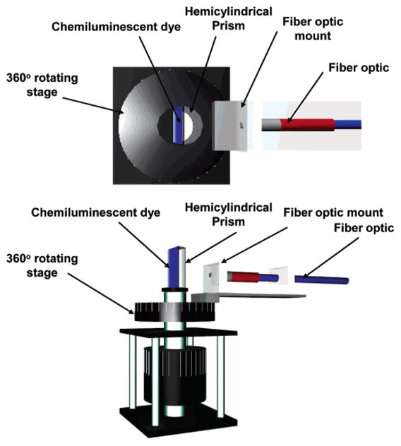
Experimental geometry used for surface plasmon-coupled chemiluminescence (SPCC). Top, view from the top; bottom, side view.
2. Materials and Methods
2.1. Materials
Premium quality APS-coated glass slides (75 × 25 mm), silver wire (99.99+% purity), aluminum evaporation slugs (99.999% purity), and silicon monoxide pieces (99.99% purity) were obtained from Sigma-Aldrich (St. Loius, MO). Gold evaporation slugs (99.999% purity) were obtained from Research and PVD Material Corporation (Wayne, NJ). CoverWell imaging chamber gaskets with adhesive (20-mm diameter, 1-mm deep) were obtained from Molecular Probes (Eugene, OR). The smaller imaging chambers were built in-house using electrical black tape, double sticky tape, and microscope coverslips. Several standard chemiluminescence kits from Omnioglow (West Springfield, MA) and Night Magic (Union City, OH) were used as the source of chemiluminescence.
2.2. Chemiluminescent Dyes
The chemiluminescent materials used in this study were obtained from commercially available kits. These kits contain the reacting chemicals encapsulated inside a plastic tube. The plastic tube contains a phenyl oxalate ester and a fluorescent dye. This fluorescent dye determines the color of the luminescence. Inside the plastic tube lies a glass capsule containing the activating agent (in this case, hydrogen peroxide). Activation of the chemicals is accomplished with a bend, snap, and vigorous shake of the plastic tube which breaks the glass capsule containing the peroxide and mixes the chemicals to begin the chemiluminescence reaction. The hydrogen peroxide oxidizes the phenyl oxalate ester to a peroxyacid ester and phenol. The unstable peroxyacid ester decomposes to a peroxy compound and more phenol. The cyclic peroxy compound is also unstable and hence gives off energy to the dye as it decomposes to carbon dioxide. The dye then radiates this energy as chemiluminescence.
2.3. Formation of Continuous Thin Films of Metal on APS-Coated Glass Substrates
Twenty nanomenters of aluminum, 45 nm of silver, and 40 nm of gold were deposited on separate APS-coated glass slides using an Edwards Auto 306 Vacuum Evaporation chamber (West Sussex, U.K.) under ultrahigh vacuum (<3 × 10⁻⁶ Torr). In each case, the metal deposition step was followed by the deposition of 5 nm of silica via evaporation without breaking vacuum. This step served to protect the metal surface from attack by the various chemical species present in the chemiluminescence assay.
2.4. Surface Plasmon-Coupled Chemiluminescence (SPCC) of Dyes on Continuous Metal Films
The surface plasmon-coupled chemiluminescence (SPCC) experiments were performed using several different colors of the chemiluminescent dyes ranging from blue to red. They were carried out by first bending the plastic tube of the chemiluminescence kit and shaking it vigorously. This allowed the reaction mixtures to mix and begin to luminesce. The tubes were then cut with a scissor, and the reacting fluid was poured into a glass vial. Approximately 150 μL of the reacting fluid was then placed in an imaging chamber gasket with adhesive (20-mm diameter, 1-mm deep). This gasket was then pressed against an (APS-coated) continuous metal-coated and silica-capped microscope glass slide until they were stuck together creating a chamber containing the chemiluminescent dyes on the surface of the metal-coated glass slide. For smaller samples, approximately 50 μL of the reacting fluid was placed in an imaging chamber built in-house attached to an (APS-coated) continuous metal-coated and silica-capped microscope glass slide.
2.5. Surface Plasmon-Coupled Chemiluminescence (SPCC) Measurements
The metal-coated slides containing the chemiluminescent dyes were attached to a hemicylindrical prism made with BK7 glass (n = 1.52), and the refractive index was matched using spectrophotometric grade glycerol (n = 1.475) between the back of the glass slide (uncoated side) and the prism. This unit was then placed on a precise 360° rotatory stage which was built in-house. The rotatory stage allowed the collection of light at all angles around the sample chamber. An Ocean Optics low OH 1000 μm diameter optical fiber with NA of 0.22 (Dunedin, FL) used for collecting the chemiluminecence signals was mounted on a holder that was screwed onto the base of the rotatory stage. A pictorial representation of the top and side view of the setup is presented in Figure 1. Surface plasmon-coupled chemiluminescence (SPCC) spectra were collected using a model SD 2000 Ocean Optics spectrometer (Dunedin, FL) connected to the above-mentioned optical fiber. The spectra were collected with an integration time between 0.5 and 2 s (depending on the intensity of the various SPCC signals). Both unpolarized and p- and s-polarized signal information was collected for the SPCC signal (from 0 to 180° with respect to the front of the prism) and for the free-space signal (from 180 to 360° with respect to the front of the prism). A separate time-dependent decay study was performed on each chemiluminescent dye to study the comparative time-dependent decay profile of the SPCC signal and the free-space signal.
3. Results and Discussion
Figure 2 (top left) shows the surface plasmon-coupled chemiluminescence (SPCC) and the free-space emission from the blue chemiluminescent dye on a 20-nm aluminum layer. It can be seen that the free-space emission is of much higher magnitude than the SPCC signal. This is because the sample chamber is 1-mm thick and only the luminophores within approximately 250 nm of the surface of silver are known to excite surface plasmons.8,9 Hence, the majority of the luminophores in the chamber do not couple to plasmons and so radiate their energy in the form of free-space emission. We subsequently attempted to use very thin films of liquid to alleviate this effect. However, the hydrophobic nature of the surface globulated the chemiluminescence liquid, preventing films <250 nm thick to be produced. Given that clinical/biochemical assays are typically performed on surfaces substantially thinner than 250 nm, as we have shown in numerous SPCE publications, we expect surface-bound chemiluminescence assays to be also highly useful.15–20 Figure 2 (top right) is an enlarged figure showing the highly directional and predominantly p-polarized SPCC emission only, suggesting that the observed signal is due to surface plasmons. This is in stark contrast to the free-space emission which does not show any polarization or directional preference. However, the signal at the SPCC peak angle is not entirely p-polarized. This is in contrast with our past experiences with optically pumped SPCE experiments where the SPCE signal was almost entirely p-polarized.8–9,15–20 The camera located at the SPCC peak angle of the figure depicts the approximate angular position where photographs of the coupled emission at various polarizations were taken. These photographs will be presented later in the section. Figure 2 (bottom) is the normalized SPCC and free-space emission spectra showing a high degree of overlap between the spectra. This suggests the plasmon-coupled chemiluminescence has not undergone any changes in its spectral properties because of the interaction between the luminescent species and the metal surface.
Figure 2.

Surface plasmon-coupled chemiluminescence from 20-nm-thick aluminum films. Top right, enlarged directional SPCC; top left, free-space chemiluminescence and SPCC; bottom, emission spectra of both the free-space chemiluminescence and SPCC.
Figure 3 (top left) shows the surface plasmon-coupled chemiluminescence (SPCC) and the free-space emission from the green chemiluminescent dye on a 45-nm silver layer. Similar to the case of the blue dye on aluminum, it can also be seen here that the free-space emission is of greater magnitude than the SPCC signal. Figure 3 (top right) is an enlarged figure showing the highly directional and predominantly p-polarized SPCC emission only, suggesting that the observed signal is due to surface plasmons. This again is in stark contrast to the free-space emission which does not show any polarization or directional preference. Figure 3 (bottom) is the normalized SPCC and free-space emission spectra showing a high degree of overlap between the spectra, suggesting no additional interaction between the luminescent species and the metal surface.
Figure 3.

Surface plasmon-coupled chemiluminescence from 45-nm-thick silver films. Top right, enlarged directional SPCC; top left, free-space chemiluminescence and SPCC; bottom, emission spectra of both the free-space chemiluminescence and SPCC.
Figure 4 (top left) shows the surface plasmon-coupled chemiluminescence (SPCC) and the free-space emission from the red chemiluminescent dye on a 42-nm gold layer. Figure 4 (top right) is an enlarged figure showing the highly directional and predominantly p-polarized SPCC emission only, suggesting that the observed signal is due to surface plasmons. The SPCC again is in stark contrast to the free-space emission which does not show any polarization or directional preference. Figure 4 (bottom) is the normalized SPCC and free-space emission spectra showing a high degree of overlap between the spectra, suggesting no other interaction between the luminescent species and the metal surface.
Figure 4.

Surface plasmon-coupled chemiluminescence from 42-nm-thick gold films. Top right, enlarged directional SPCC; top left, free-space chemiluminescence and SPCC; bottom, emission spectra of both the free-space chemiluminescence and SPCC.
Figure 5 shows photographs of the coupled emission (from the prism side) at the respective SPCC peak angle from the various dyes at both s- and p-polarizations as well as with no polarization. The approximate angular location of the camera used obtaining these photographs is marked in Figures 2–4 (top right). This figure clearly shows that the emission at the SPCC peak angle is predominantly p-polarized for all three dyes (on all three metals) thus suggesting that surface plasmons are responsible for the SPCC signal, as has been demonstrated for fluorophores.8,9 It can be seen that the p-polarized signal intensity at the SPCC peak angle is lower in magnitude than the unpolarized signal. This occurs because the entire SPCC signal consists of both p- and to a lesser degree s-polarized light, and also because the sheet polarizers used in the experiment have only 30–40% peak transmission efficiency for both polarizations.
Figure 5.

Photographs of the coupled emission at various polarizations for gold, silver, and aluminum films, top to bottom, respectively, taken at their respective SPCC peak angles. See location of camera in Figures 2–4 (top right).
Initially, the broadness of the SPCC peak angles for all three dyes which varied between 20 and 25 degrees was of concern to us (Figures 2–4 (top right)). This was unlike our past experiences with optically pumped SPCE studies for a thin layer of fluorophores, where the SPCE peak angle was approximately 1–2 degrees wide.8–9,15–20 Hence, to investigate whether the broadness of the SPCC peak angle is a function of the surface area of the sample, we repeated the experiment (on silver using the green chemiluminescent dye) with a sample chamber built in-house that had approximately half the surface area when compared to the samples made with commercially available imaging chambers that had been used thus far. Figure 6 (top left) shows the surface plasmon-coupled chemiluminescence (SPCC) and the free-space emission from the green chemiluminescent dye on a 45-nm silver layer for the small imaging chambers built in-house. Figure 6 (top right) is an enlarged figure showing the highly directional and predominantly p-polarized SPCC emission only. Here, the broadness of the SPCC peak angle is approximately 20 degrees. It is clear from this figure that the broadness of the SPCC peak angle is not significantly affected by the surface area of the sample. An interesting observation in Figure 6 (top right) is the decay in the SPCC signal in the region between 90 and 180 degrees when compared to that in the 0–90 degrees. This is because the data was collected sequentially from 0 through 360 degrees. As a result, for the small chamber with a lower volume of reactants, by the time the data in the region between 90 and 180 degrees was collected, a signal reduction is observed because of the depletion of reactants (depletion of excited states) over time. Our laboratory has reported the effects of fluorophores in thick plastic and PVA films (>250 nm) above 50-nm-thick metallic continuous surfaces.15,21 Similar to our findings here in this study, these reports also show a broader angle dependence of SPCE because of waveguide modes.15,21 Hence, we attribute the broad angle distribution shown in Figures 2–4 and 6 to this waveguide effect, given that our solution of chemiluminescence occupied a sample chamber of 1-mm thickness. Figure 6 (bottom) is the normalized SPCC and free-space emission spectra showing a high degree of overlap between the spectra, suggesting no additional interaction between the luminescent species and the metal surface in the smaller imaging chambers built in-house.
Figure 6.

Surface plasmon-coupled chemiluminescence (SPCC) and free-space chemiluminescence from a small sample chamber, top left, and the enlarged coupled region, top right. Bottom, emission spectra of both free-space chemiluminescence and SPCC from the small chamber.
The next round of experiments was performed to determine the rate of decay of luminescence for the blue and green chemiluminescent dyes as a function of time for both the free-space emission and the SPCC emission (with p-polarizers so that only plasmon-coupled emission was measured). By decay rate, we mean the decrease in intensity because of depletion of reagents. The results of these experiments for the blue dye on aluminum and green dye on silver are shown in Figures 7 and 8, respectively. Figure 7 (top) shows the decay of free-space and SPCC emission as a function of time for the blue dye on aluminum, with Figure 7 (bottom) image showing both the decay intensities normalized to their respective values at t = 0. The rate of loss of luminescence, which is due to the depletion of solution reactants and therefore a depletion over time of excited states, was found to follow first-order decay kinetics and can be modeled to an exponential function of the form
Figure 7.

Chemiluminescence intensity decays from aluminum films for both free space and coupled (top) and normalized to the same initial intensity (bottom).
Figure 8.

Chemiluminescence intensity decays from silver films for both free space and coupled (top) and normalized to the same initial intensity (bottom).
| (1) |
where C is the intensity at time t = ∞, B is a preexponential factor, and k is the rate of luminescence depletion, units s−1. The rate of depletion of the SPCC signal for the blue dye on aluminum was found to be only minimally greater than the free-space emission, 0.0003 versus 0.0002 s−1, respectively. Since both the SPCC signal and the free-space emission signal decay are highly dependent on the rate of depletion of the same reactants (depletion of excited states) in the sample chamber over time, it is not surprising that the measured decay rates for both the signals as shown in Figure 7 are almost identical. However, this finding does indicate that there are no localized catalytic effects of the aluminum on the chemiluminescence reaction, as this would be expected to manifest in a larger difference in the SPCC luminescence decay rate (from the free-space decay rate) than is currently observed.
Figure 8 (top) shows the decay of free-space and SPCC emission as a function of time for the green chemiluminescent dye on silver, and Figure 8 (bottom) shows both the decay intensities normalized to their respective values at t = 0. The rate of depletion of the SPCC signal for the green dye on silver was found to be only minimally smaller than the free-space emission, 0.0005 versus 0.0006 s−1, respectively. It is again not surprising that the measured decay rates for both the signals as shown in Figure 8 are almost identical, since both the SPCC signal and the free-space emission signal decay are highly dependent on the rate of depletion of the same reactants in the sample chamber over time. This finding again indicates no localized catalytic or chemical effects of the silver on the chemiluminescence reaction studied.
4. Conclusions
The results of this study lead us to conclude that chemically induced electronic excited states of luminophores can excite surface plasmons on thin films of continuous metal, producing highly polarized and directional emission. We believe this phenomenon is not restricted to the commercially available kits that were used in this study but rather can be extended to the myriad of chemiluminescent reactions employed in biotechnology today to increase signal collection efficiency and hence the sensitivity of such assays. The typical thickness of the functional surface of such assays are compatible with an approximately 250-nm coupling region,15–20 potentially alleviating unwanted background signals caused by spontaneous reaction of reagents or unwanted enzymatic activity and therefore increasing assay sensitivity. In this regard, work is underway in our laboratories and will be reported in due course. Another interesting observation is that SPCC occurs with gold films. This is of importance since the absorption bands of gold often lead to fluorescence quenching possibly by resonance energy transfer to the gold absorption bands.23–26 Since luminophores within approximately 250 nm of the surface of metal are known to excite surface plasmons,8,9 which is longer than the distances required for nonradiative quenching of luminescence, the potential of using gold as the metal surface becomes an advantage. This is because gold is chemically more stable than silver and the surface chemistry of gold is well-known and characterized.27 Also, since gold films are widely used in surface plasmon resonance (SPR), this provides a robust technology base for the mass production of suitable gold films.16 Hence, we believe that the use of plasmonic coupling to efficiently collect chemiluminescence signals will be a valuable addition in bioassays that employ chemiluminescence.
Acknowledgments
This work was supported by the NIH (Grant No. GM070929) and the National Center for Research Resources (Grant No. RR008119) and EB00682. Salary support to C.D.G., K.A., and J.R.L. from UMBI is also acknowledged.
References and Notes
- 1.Garcia-Campana AM, Baeyens WR. Analytical Chemistry. Marcel Dekker; New York: 2001. [Google Scholar]
- 2.Wampler JE. In: Chemi- and Bioluminescence. Burr JG, editor. Marcel Dekker; New York: 1985. p. 1. [Google Scholar]
- 3.Berthold F. In: Luminescence Immunoassays and Molecular Applications. Van Dyke K, Van Dyke R, editors. CRC Press; Boca Raton, FL: 1990. p. 11. [Google Scholar]
- 4.Nieman T. Encyclopedia of Analytical Science. Academic Press; Orlando, FL: 1995. Chemiluminescence: Theory and Instrumentation. [Google Scholar]
- 5.Lakowicz JR. Principles of Fluorescence Spectroscopy. Kluwer/Academic Plenum; New York: 1997. [Google Scholar]
- 6.Lakowicz JR. Anal Biochem. 2001;298:1–24. doi: 10.1006/abio.2001.5377. [DOI] [PMC free article] [PubMed] [Google Scholar]
- 7.Lakowicz JR. Anal Biochem. 2002;301:261–277. doi: 10.1006/abio.2001.5503. [DOI] [PMC free article] [PubMed] [Google Scholar]
- 8.Lakowicz JR. Anal Biochem. 2004;324:153–169. doi: 10.1016/j.ab.2003.09.039. [DOI] [PMC free article] [PubMed] [Google Scholar]
- 9.Gryczynski I, Malicka J, Gryczynski Z, Lakowicz JR. Anal Biochem. 2004;324:170–182. doi: 10.1016/j.ab.2003.09.036. [DOI] [PMC free article] [PubMed] [Google Scholar]
- 10.Geddes CD, Aslan K, Gryczynski I, Malicka J, Lakowicz JR. Noble metal surface for metal-enhanced fluorescence. In: Geddes CD, Lakowicz JR, editors. Annual Reviews in Fluorescence. Kluwer Academic/Plenum; New York: 2004. p. 365. [Google Scholar]
- 11.Aslan K, Leonenko Z, Lakowicz JR, Geddes CD. J Fluoresc. 2005;15(5):643–654. doi: 10.1007/s10895-005-2970-z. [DOI] [PMC free article] [PubMed] [Google Scholar]
- 12.Lakowicz JR. Radiative Decay Engineering 5. Anal Biochem. 2005;337:171–194. doi: 10.1016/j.ab.2004.11.026. [DOI] [PMC free article] [PubMed] [Google Scholar]
- 13.Chowdhury MH, Aslan K, Malyn SN, Lakowicz JR, Geddes CD. Appl Phys Lett. 2006;88:173104. doi: 10.1063/1.2195776. [DOI] [PMC free article] [PubMed] [Google Scholar]
- 14.Chowdhury MH, Aslan K, Malyn SN, Lakowicz JR, Geddes CD. J Fluoresc. 2006;16:295–299. doi: 10.1007/s10895-006-0082-z. [DOI] [PMC free article] [PubMed] [Google Scholar]
- 15.Gryczynski I, Malicka J, Nowaczyk K, Gryczynski Z, Lakowicz JR. J Phys Chem B. 2004;108:12073–12083. doi: 10.1021/jp0312619. [DOI] [PMC free article] [PubMed] [Google Scholar]
- 16.Gryczynski I, Malicka J, Gryczynski Z, Lakowicz JR. J Phys Chem B. 2004;108:12568–12574. doi: 10.1021/jp040221h. [DOI] [PMC free article] [PubMed] [Google Scholar]
- 17.Geddes CD, Gryczynski I, Malicka J, Gryczynski Z, Lakowicz JR. J Fluoresc. 2004;14:119–123. doi: 10.1023/b:jofl.0000014809.64610.a8. [DOI] [PMC free article] [PubMed] [Google Scholar]
- 18.Gryczynski I, Malicka J, Gryczynski Z, Nowaczyk K, Lakowicz JR. Anal Chem. 2004;76:4076–4081. doi: 10.1021/ac040004c. [DOI] [PMC free article] [PubMed] [Google Scholar]
- 19.Matveeva E, Gryczynski Z, Gryczynski I, Malicka J, Lakowicz JR. Anal Chem. 2004;76:6287–6292. doi: 10.1021/ac0491612. [DOI] [PMC free article] [PubMed] [Google Scholar]
- 20.Gryczynski I, Malicka J, Jiang W, Fischer H, Chan WCW, Gryczynski Z, Grudzinski W, Lakowicz JR. J Phys Chem B. 2005;109:1088–1093. doi: 10.1021/jp046173i. [DOI] [PubMed] [Google Scholar]
- 21.Gryczynski I, Malicka J, Nowaczyk K, Gryczynski Z, Lakowicz JR. Thin Solid Films. 2006;510:15–20. doi: 10.1016/j.tsf.2005.07.312. [DOI] [PMC free article] [PubMed] [Google Scholar]
- 22.Zhang J, Gryczynski Z, Lakowicz JR. Chem Phys Lett. 2004;393:483–487. doi: 10.1016/j.cplett.2004.06.050. [DOI] [PMC free article] [PubMed] [Google Scholar]
- 23.Du H, Disney MD, Miller BL, Krauss TD. J Am Chem Soc. 2003;125:4012–4013. doi: 10.1021/ja0290781. [DOI] [PubMed] [Google Scholar]
- 24.Dubertret B, Calame M, Libchaber AJ. Nat Biotechnol. 2001;19:365–370. doi: 10.1038/86762. [DOI] [PubMed] [Google Scholar]
- 25.Dulkeith E, Morteani AC, Niedereichholz T, Klar TA, Feldmann J, Levi SA, van Veggel FCJM, Reinhoudt DN. Phys Rev Lett. 2002;89(20):203002. doi: 10.1103/PhysRevLett.89.203002. [DOI] [PubMed] [Google Scholar]
- 26.Liu L, Wang T, Guo ZX, Dai L, Zhang D, Zhu D. Chem Phys Lett. 2003;367:747–752. [Google Scholar]
- 27.Aslan K, Pérez-Luna VH. Langmuir. 2002;18:6059–6065. [Google Scholar]