

Abstract
A new method of fluorescence detection that promises to increase sensitivity by 20- to 1000-fold is described. This method will also decrease the contribution of sample autofluorescence to the detected signal. The method depends on the coupling of excited fluorophores with the surface plasmon resonance present in thin metal films, typically silver and gold. The phenomenon of surface plasmon-coupled emission (SPCE) occurs for fluorophores 20–250 nm from the metal surface, allowing detection of fluorophores over substantial distances beyond the metal–sample interface. SPCE depends on interactions of the excited fluorophore with the metal surface. This interaction is independent of the mode of excitation; that is, it does not require evanescent wave or surface-plasmon excitation. In a sense, SPCE is the inverse process of the surface plasmon resonance absorption of thin metal films. Importantly, SPCE occurs over a narrow angular distribution, converting normally isotropic emission into easily collected directional emission. Up to 50% of the emission from unoriented samples can be collected, much larger than typical fluorescence collection efficiencies near 1% or less. SPCE is due only to fluorophores near the metal surface and may be regarded as emission from the induced surface plasmons. Autofluorescence from more distal parts of the sample is decreased due to decreased coupling. SPCE is highly polarized and autofluorescence can be further decreased by collecting only the polarized component or only the light propagating with the appropriate angle. Examples showing how simple optical configurations can be used in diagnostics, sensing, or biotechnology applications are presented. Surface plasmon-coupled emission is likely to find widespread applications throughout the biosciences.
Fluorescence detection is the basis for numerous assays in the biological sciences, biotechnology, and medical diagnostics. Fluorescence is a highly sensitive method, but there is always a need for increased sensitivity to detect smaller numbers of target molecules. Numerous methods to increase sensitivity have been developed. These methods include amplified assays such as enzyme-linked immunosorbent assay [1] and PCR [2], probes with multiple fluorophores such as the phycobiliproteins [3,4], long-wavelength probes [5,6], and/or gated detection to decrease the background emission [7,8]. Several fundamental factors limit the sensitivity of fluorescence methods, typically photodestruction of the fluorophores and the extent of background fluorescence.
At present essentially all fluorescence detection relies on the emission of fluorophores under free-space conditions, that is, emission into a transparent nonabsorbing medium typical of biological samples. In such samples the fluorophores emit mostly isotropically in all directions with a radiative decay rate (Γ) given approximately by the Strickler and Berg equation [9]. In a recent series of papers we began to explore fluorescence detection under conditions where the radiative decay rate was changed. One well-known example is the effect of refractive index on fluorescence decay times as exemplified by the Strickler and Berg equation [9] showing that the radiative decay rate of an oscillating dipole increases in proportion to n2, where n is the refractive index of the medium.
The effects of refractive index on fluorescence is modest and is seldomly used in fluorescence experiments [10–12]. However, there is a simple way to profoundly change radiative decay rates and spatial distribution of the radiated energy. This can be accomplished with metallic surfaces or particles, typically silver and gold. Examples of the effects of metals on fluorescence include the oscillations of lifetimes with distance in front of a mirror [13,14] and the decreased emission rate of fluorophores between closely spaced mirrors [15–17]. The effects in front of a mirror are modest, typically 30%, and fewer results are available for fluorophores between mirrors with nanometer-scale distances.
In a recent series of papers we began using a different approach to modification of the emissive properties of fluorophores. Our approach relies on the large effects of conducting metallic silver particles and colloids. We found that proximity of fluorophores to silver particles resulted in increased intensities, quantum yields, and photostability [18–22]. These effects were accompanied by dramatically decreased lifetimes, indicating a substantial increase in the radiative decay rates. We also observed release of fluorophores self-quenching [23,24] and enhanced emission near fractal and light-deposited silver structures [25,26]. These results illustrate the useful potential of modifying fluorescence using metals, especially for increased sensitivity.
One approach to increased sensitivity is to increase the fraction of the total emission collected by the instrument. Fluorescence is isotropic and it is difficult to collect more than a small fraction of the emitted photons. The importance of light collection efficiency can be seen by consideration of the requirements for single-molecule detection [27–29]. A typical fluorophore can undergo a finite number of excitation–relaxation cycles prior to photochemical destruction. For photostable molecules, such as tetramethylrhodamine, photodestruction occurs after about 105 cycles. However, the number of photons detectable from a single fluorophore is typically much smaller, near 103 photons. This decrease is due in part to the isotropic distribution of fluorescence, which makes it difficult to capture more than a small fraction of the total emission. According to Keller, even efficient detection systems capture only about 1% of the total emission, and typically less [29]. Higher collection efficiencies near 10% are possible [30,31], but at the expense of complex optics.
In the present paper a new approach to collection of fluorescence which can provide 50% light collection efficiency using simple and inexpensive optics is described. This new opportunity in fluorescence detection is based on the interaction of excited-state fluorophores with a nearby continuous metallic surface. It is shown that fluorophores above a metal surface can couple with the plasmon resonances in the surface, resulting in directional and wavelength-resolved emission. Surface plasmon-coupled emission (SPCE)1 is the reverse process of surface plasmon resonance (SPR) as seen in the angle-dependent absorption of thin metal films. This novel utilization of fluorophore–metal interactions promises to have numerous applications in the biosciences. The organization of this article is as follows. First, the principles of surface plasmon resonance as applied to biomolecule association reactions is described. This overview of SPR provides the background to understand how fluorophores interact with thin metal films. Second, how this interaction can result in efficient light collection and directional emission is shown. Third, the potential applications of this useful phenomenon are considered. This article does not describe the physics theory of SPCE. Such a presentation would include complex equations and would not serve to introduce SPCE to scientists interested in the applications of this phenomenon.
Surface plasmon resonance
Surface plasmon resonance analysis
The phenomenon of surface plasmon resonance provides a simple and intuitive approach to understanding SPCE. The term surface plasmon resonance can refer to the phenomenon itself (SPR) or to the use of this phenomenon to measure biomolecule binding to surfaces. To avoid confusion we refer to this latter application of SPR as surface plasmon resonance analysis (SPRA). This method is now widely used in the biosciences and provides a generic approach to measurement of biomolecule interactions on surfaces [32–36]. A schematic description of SPRA is shown in Fig. 1. The measurement is based on the interaction of light with thin metal films on a glass substrate. The film is typically made of gold 40–50 nm thick. The analysis surface consists of a capture biomolecule which has affinity for the analyte of interest. The capture biomolecule is typically covalently bound to the gold surface. The analysis substrate is optically coupled to a hemispherical or hemicylindrical prism by an index matching fluid. Light impinges on the gold film through the prism, which is called the Kretschmann configuration. The instrument measures the reflectivity of the gold film at various angles of incidence (θ), with the same angle used for observation (θ). Other configurations can be used, such as a triangular prism or more complex optical geometry and a position-sensitive detector. In any event the measurement is the same, reflectivity of the gold surface versus angle of incidence.
Fig. 1.

Typical configuration for surface plasmon resonance analysis. The incident beam is p-polarized.
The usefulness of SPRA is due to the large dependence of the gold film reflectivity on the refractive index of the solution immediately above the gold film. Binding of macromolecules above the gold film causes small changes in the refractive index which result in changes in reflectivity. Fig. 2 shows typical SPRA data, a plot of reflectivity versus the angle of incidence for a 47-nm gold film, a thickness thought to be ideal for SPRA [37–39]. The reflectivity minimum occurs at the SPR angle. The SPR angles change as the gold surface is coated with 11-mercaptoundecanoic acid, then biotinylated poly-lysine, and finally avidin. The changes in SPR angle are due to changes in refractive index near the gold surface due to the adsorbed layers.
Fig. 2.

SPR reflectivity curves for a 47-nm gold film on BK-7 glass. Illumination was at 633 nm. The gold film was progressively coated with 11-mercaptoundecanoic acid (MU), followed by biotinylated poly-lysine (PL), and then avidin. Adapted from [37–39].
The decrease in reflectivity at the SPR angle (θSP) is due to absorption of the incident light at this particular angle of incidence. At this angle the incident light is absorbed and excites electron oscillations on the metal surface. It is important to understand why the reflectivity is sensitive to the refractive index of the aqueous medium if the light is reflected by the gold film. This sensitivity is due to an evanescent field which penetrates approximately 200 nm into the solution (Fig. 1). The evanescent field appears whenever there is resonance between the incident beam and the gold surface and is not present when there is no plasmon resonance, that is, where the reflectivity is high.
The existence of an evanescent field is reminiscent of total internal reflectance (TIR) which occurs between a glass–water interface when the angle of incidence from the glass slide exceeds the critical angle [40]. There is often confusion about the relationship between the critical angle in TIR (θC) and the SPR angle (θSP). The physical origins of θC and θSP are similar, but these angles are different and not directly related. This difference between θC and θSP is illustrated in Fig. 3, which compares glass and silver-coated glass surfaces. The silver-coated surface shows high reflectivity at all angles except near the plasmon angle near 30°. The reflectivity of a glass surface is quite different. The reflectivity is low below the critical angle θC and increases sharply to nearly 100% at θC, and the reflectivity remains high for all angles above θC. For the glass surface and angles above θC there exists an evanescent field from the totally internally reflected light. For the silver-coated glass there is no evanescent field in the aqueous phase unless the angle of incidence is near the SPR angle. The reflectivity of the silver film is high at angles significantly larger or smaller than θSP.
Fig. 3.
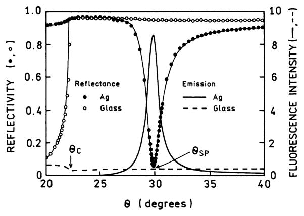
Reflectivity curves for bare glass and silver-coated glass, both spin-coated with a fluorophore in polyvinyl alcohol. Prism is LaSFN9 glass, 633 nm. Also shown is the fluorescence from the labeled PVA film on the glass and silver surfaces. Adapted from [41,42].
The evanescent wave due to SPR is much more intense than that due to TIR. The relative strengths of the fields can be measured by the fluorescence from fluorophores near the surface. For Fig. 3, fluorophores were localized within the evanescent field by coating with a polyvinyl alcohol (PVA) film which contained a fluorophore [41]. The dependence of the emission on incident angle indicates the relative intensity of the evanescent wave felt by the fluorophores. For the glass surface the emission intensity is low for θ < θC. This low value is essentially the same as that seen in a typical fluorescence measurement where the fluorophore is excited in a glass or quartz cuvette. As the incident angle exceeds θC the intensity drops about twofold because the incident light undergoes TIR rather than passing into the sample. Above the critical angle the remaining intensity represents the amount of excitation due to the TIR evanescent wave. This result indicates that the field strength for TIR is roughly the same for the incident light and the evanescent wave. For clarity we note that the intensity on glass seen for θ < θC will increase with the thickness of the PVA film. The intensity for θ > θC will be mostly independent of the film thickness once it exceeds the penetration depth of the evanescent wave.
Remarkably, different results are seen for the labeled film on the silver surface. The emission intensity is near zero for angles above and below θC because of the high reflectivity of the metal film. In contrast to uncoated glass, the light does not penetrate the sample even though θ < θC. There is a dramatic increase (about 15-fold) in the emission intensity of the film near the plasmon angle. This effect is due to a 10- to 40-fold increase in the intensity of the evanescent field above silver as compared to that above glass with TIR [42–46]. This increase in field strength above a metal film is one origin of the increased sensitivity possible with plasmon-coupled emission.
An important characteristic of the SPR angles is that they are strongly dependent on wavelength. Fig. 4 shows the reflectivity curves of a gold film for several wavelengths [47]. The surface plasmon angle decreases as the wavelength decreases. The dependence on wavelength can be understood with regard to the optical constants of the metals, which depend upon wavelength (frequency) and the dielectric constant of the sample and prism. This dependence of θSP on wavelength is the origin of intrinsic spectral resolution when observing surface plasmon-coupled emission.
Fig. 4.
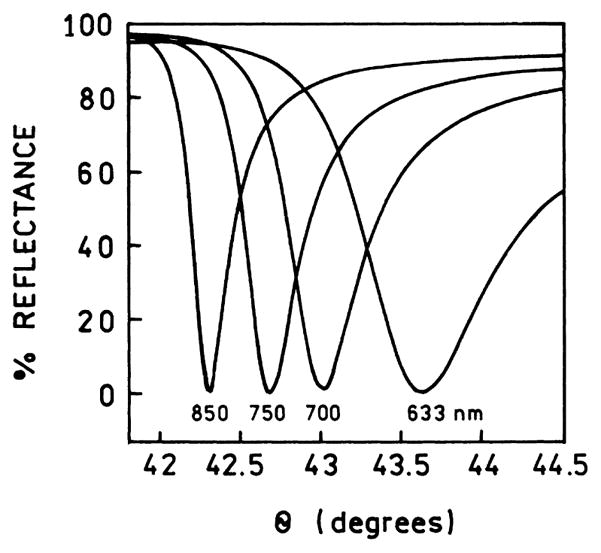
Calculated wavelength-dependent reflectivity for a 47-nm-thick gold film. From [47].
The theory of SPR provides a basis for understanding SPCE. Prior to describing the theory of SPR it is informative to understand the angular shift in θSP measuring during SPRA. Examination of Figs. 2 and 4 may give the impression that the changes in θSP due to bio-molecule binding are several degrees. A scan of the SPRA literature shows that in most experiments the changes upon biomolecule binding are reported in relative units (RU) [48–52]. A typical experiment is shown in Fig. 5. The change in RU is measured during the binding reaction, in this case binding of bovine serum albumin BSA to a dextran-coated gold surface. The sample is initially washed with buffer (B). Washing with BSA causes a change of about 1 kRU, which can be reversed by washing with buffer. This change is due to the effect of BSA on the refractive index of the solvent. To determine the effect of surface-bound BSA the dextran was activated with coupling reagents (NHS/EDC), incubated with BSA, and then washed with buffer. Covalent coupling of BSA to the surface results in a non-reversible change of about 1 kRU. Even this moderately dense coating of protein results in a change of just 1 kRU. 1 RU is defined as a shift in the SPR angle of 10−4 degrees [52]. Hence, the changes in θSP during SPRA are very small, typically 0.1°. As will be shown below, this small change in SPR with biomolecule binding indicates that surface binding reactions will not interfere with the intrinsic spectral resolution of plasmon-coupled emission.
Fig. 5.
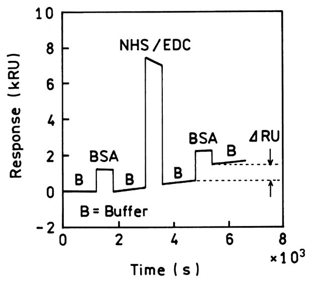
Surface plasmon resonance analysis of noncovalent and covalent binding of BSA to a dextran-coated gold surface. B, buffer; BSA, bovine serum albumin; NHS/EDC, covalent coupling reagents. 1 RU = 10−4 degrees. From [52].
Theory of surface plasmon resonance
Knowledge of the theory of SPR is essential for understanding surface plasmon-coupled emission. The theory to describe the reflectivity of metal-coated surfaces is complex. It can be difficult to understand the underlying physical interactions that are responsible for angle-dependent absorption. The detailed equations needed to calculate the reflectivity will not be described. Instead, the phenomenon itself will be examined. To understand SPR it is helpful to review the physical origin of Snell’s law. Fig. 6 shows the propagation of light across an interface where the dielectric constant of the prism (nP) is greater than that of the air (n0). The angles of the incident (θP) and refracted (θ0) beams are related by Snell’s law.
Fig. 6.
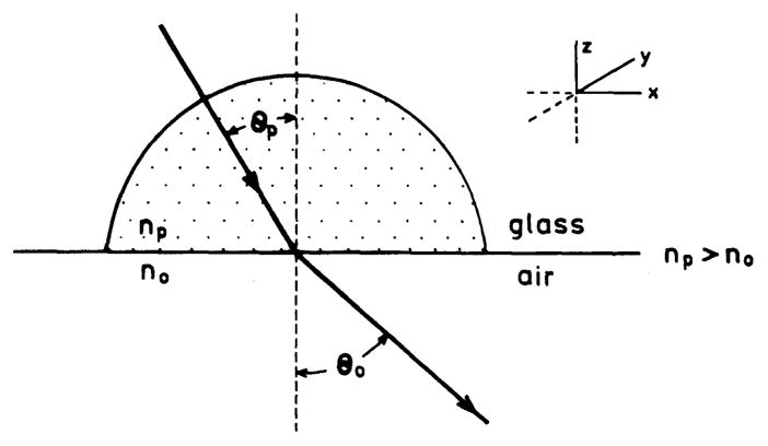
Propagation of light from a high refractive index medium (nP) to a low refractive index medium n0. For n0 = 1, nP = 1.5, and θP = 30.0, the θ0 = 48.6°.
| (1) |
For example, suppose that θP = 30° and that the index of refraction is typical of glass, nP = 1.5; then θ0 = 48.6°. As the angle of incidence (θP) increases the component of the beam along the x axis in the prism also increases. It is easy to visualize the rapid increase in the x component of the field as θP increases.
TIR occurs when the refracted beam can no longer propagate in air. The largest possible component of the beam in the air along the x axis is given when θ0 = 90°, which occurs when θP is a smaller angle less than 90°. When θ0 = 90° the sin θ0 = 1.0 and the incident angle in the prism is given by
| (2) |
which is called the critical angle for TIR. For an angle of incidence equal to θC the x component is infinite. For θ > θC no angle satisfies Eq. (2) (sin θ0 > 1) and the incident beam is reflected back into the denser medium. For the case in question, the critical angle is 41.8°. If one attempts to use θP greater than 41.8° in Eq. (1) there is no solution for θ0 since the calculated value of sin θ0 > 1.0.
The phenomena of refraction and TIR can be understood with regard to Maxwell’s equation [53–55]. An electromagnetic wave propagating in space can be described by
| (3) |
where the bars indicate vector quantities, r̄ is a unit vector in the direction of propagation, ω is the frequency in radians/s, and . The term k̄ is the propagation constant which is sometimes called the wavevector. This value is given by
| (4) |
where λ = λ0/n is the wavelength, λ0 is the wavelength in a vacuum, n is the refractive index of the medium, and k0 is the propagation constant of the wave in a vacuum. It is understood that the physical values are given by the real part of Eq. (3). Hence the electric field is described by
| (5) |
For TIR we need to consider the electric field along the x axis, the prism–water interface. This component is given by
| (6) |
To satisfy Maxwell’s equations the electric fields have to be continuous across the interface, which requires kx to be equal in both media. Hence
| (7) |
Since kP = nPω/c and k0 = n0ω/c continuity across the interface requires the angles to be related according to Eq. (1).
Surface plasmon resonance can also be understood by continuity of the electric field across the interface. However, we need to consider the complex optical properties of metallic surfaces. It is well known that if an electrical field E0 is incident on a dielectric material the field within the material is E = εE0 where ε is the dielectric constant. For a dielectric the refractive index n is often related to the dielectric constant by . This relationship holds if n and ε are measured at the same frequency. For polar liquids one often finds because the dielectric constant is measured at lower frequencies where the polar molecules can reorient in the electric field.
The optical constants n and ε are more complex for metals; in fact they are described by imaginary numbers. In a dielectric all the electrons are bound to the nuclei. In a metal some of the electrons are free and can respond to an incident field. At low frequencies the metal is a conductor. At higher frequencies the electrons oscillate in response to the oscillating incident field. While the electrons in a metal are highly mobile, they are not infinitely fast. The rate of electron motion in response to an applied field can be understood in terms familiar to time-resolved spectroscopy. Suppose the electrons are moving with a velocity v0 in response to an electric field. When the field is turned off the velocity decays exponentially as v = v0 exp(−βt), where β is the decay constant with a value near 3 × 10¹³ s−1 [55,56]. The relaxation times (1/β) are very fast and are near 0.03 ps = 30 fs. Consider light with a wavelength of 500 nm, which corresponds to a frequency of 0.6 × 10⁻¹⁵ s−1. The electrons respond to the electric field but cannot keep up completely, which would happen at longer wavelengths where the frequency is lower. At shorter wavelengths or higher frequencies the electrons cannot respond and the material may become transparent if other absorption bands are not present. The optical and reflective properties of silver and gold depend on the interplay of incident frequency and electron mobility in addition to underlying absorption bands not related to electron oscillations.
This interplay of electron mobility and incident frequency results in complex and imaginary optical constants. The refractive index and dielectric constants of a metal are given by
| (8) |
and
| (9) |
where subscripts indicate the real (r) and imaginary (im) components. These constants are wavelength (frequency) dependent. Some intuition about the physical meaning of these terms can be obtain from examining specific examples [57–60] of gold and silver, which are expected to be most useful metals for SPCE. Fig. 7 shows the dielectric constants for gold and silver calculated using [57]. The imaginary part of the dielectric constant is small and positive. The imaginary part is related to light absorption, which can be seen by the larger values of εim of gold for wavelengths below 500 nm. The real part of εm becomes increasingly more negative as the wavelength increase. This effect can be interpreted as electron oscillations with the charge opposite to the incident field. As the incident frequency decreases εr becomes more negative, reflecting more complete response of the electrons to the lower frequency. For a perfect conductor εr approaches minus infinity.
Fig. 7.

Complex dielectrical constants for silver and gold. Calculated from [57–60].
The phenomenon of SPR can be understood by considering the propagation constant of the electromagnetic wave in the metal along the x axis. In the metal film the field is described by Eqs. (5) and (6) with kx = kr + ikim being the complex wavevector along the x axis. For a metal the propagation constant for the surface plasmon is given by
| (10) |
where εm and εs are the dielectric constant of the metal (m) and sample (s), respectively. εs refers to the effective dielectric constant in the evanescent field (Fig. 1). Because the real part of εm is larger than the imaginary part the propagation constant can be approximated by
| (11) |
The incident light can excite a surface plasmon when its x axis component equals the propagation constant for the surface plasmon (Fig. 8). The propagation constant for the incident light in the prism (p) is given by
Fig. 8.

Schematic showing propagation constants in a prism and a thin film.
| (12) |
and the component along the x axis is equal by
| (13) |
where θp is the incidence angle in the prism. Hence the conditions for SPR absorption is satisfied when
| (14) |
These considerations show that the surface plasmon resonance occurs whenever the x axis component of the incident field equals that obtained from Eq. (11).
Detailed consideration of Eq. (10) yields some interesting insights. Suppose light is incident on the metal from a vacuum or air (n = 1.0). The maximum value of kx is given when θP = 0, yielding kx = k0. Examination of Fig. 7 shows that the real parts of εm are negative and much greater than one. These parts dominate the ratio in Eq. (10) so that kSP is always larger than the free-space wavevector k0. For this reason surface plasmons cannot be excited with light incident from the air or medium with the lower dielectric constant. The large value of kSP > k is due to the finite speed of electron motion which makes the metal less than a perfect conductor at optical frequencies.
To obtain SPR the magnitude of kx must be increased to equal or exceed kSP. This can be accomplished using the configuration shown in Fig. 1 where light is incident on the metal film from the prism side. This approach increases the wavevector to kp = np k0. The refractive index of the prism reduces the wavelength to λ = λ0/nP This results in the maxima and minima of the electric field being more closely spaced, but now kSP is less than k0. To obtain resonance the x components of the electric field distribution are then matched by adjustment of the x component of kP by a factor sin θP (Fig. 8).
We can calculate the value of θSP using Eqs. (11)–(14). These values are shown on Fig. 7. The values of θSP increase with decreasing wavelengths. Because of the wavelength-dependent dielectric constants there is a lower wavelength limit below which θSP cannot be calculated. Above this lower wavelength limit the dependence of θSP on wavelength is roughly the same for silver and gold.
During our review of SPR we search for an intuitive approach to explain the resonances at different angles and wavelengths (Fig. 4). We maintain a mental picture of the interaction by considering the wavelength of the incident light in the prism and the projection of this distance onto the interface (Fig. 8). SPR occurs when this projected distance matches the wavelength of the surface plasmon. This visualization of SPR explains the increase in θP needed for resonance at shorter wavelengths. However, the increase in θP needed for an increase in wavelength is offset in part by the wavelength-dependent properties of the metal.
While one can readily calculate θSP it is considerably more difficult to calculate the reflectivity curves as seen in Figs. 2 and 4. This requires calculation of the reflectivity of the film for a range of incidence angles. Additionally it is necessary to recall that a SPRA experiment involves at least three phases: the prism, metal, and solution containing the analyte. If one considers the region of the sample beyond the surface-bound macromolecules then one has to consider four phases. The equations are complex and can be found elsewhere [61–66]. A convenient approach is to go to http://corninfo.chem.wisc.edu. This website calculates reflectivity curves for any chosen optical constants and metal thickness for a three- or four-phase system. Reflectivity curves can also be calculated using commercial software.
Polarization relative to a surface
For individuals familiar with fluorescence polarization or anisotropy measurements the conventions used with surfaces can be confusing. For fluorescence measurements in a cuvette the symmetry axis is the z axis, so measurements of the polarized intensities are made relative to this axis. For light incident on a surface the symmetry axis is the plane of incidence formed between the incident ray and an axis normal to the surface, which is in the plane of the paper in Fig. 9. An incident ray is said to be p-polarized if the electric vector (E||) is parallel to the plane of incidence. This polarization is also referred to as TM polarized, meaning that the magnetic vector is transverse to the plane of incidence. An incident beam is said to be s-polarized (E⊥) when the electric vector is perpendicular to the plane of incidence. Such a beam is also described as TE polarized, meaning that the electric vector is transverse to the plane of incidence. For p-polarized light it is easy to see that the interaction of the electric field with the metal surface depends on θI.
Fig. 9.

Polarization definitions for light incident on a surface.
When measuring or discussing SPR one can assume that the incident beam is p-polarized. It is the p-polarized component of the beam that gives the reflectivity curves seen in Figs. 2 and 4. The s-polarized beam will not excite the surface plasmon and will not show decreased reflectivity at some angle of incidence. The origin of this difference can be understood by considering the interactions of the effective field with the metal surface; s-polarized, like the electric field, does not depend on θI.
Flourescence and thin metal films
Surface plasmon-coupled emission
We are now prepared to consider how the phenomenon of SPR can be applied to fluorescence detection. A useful clue is given in Fig. 4, which shows that the plasmon angle is different for different wavelengths. The reflection minima are more strongly dependent on wavelength compared to the effects of biomolecule binding (Fig. 5). If an incident beam can excite a surface plasmon and create an evanescent field it seems logical that an excited fluorophore can excite a surface plasmon and create a radiative beam (Fig. 10). We call this phenomenon surface plasmon-coupled emission. This reasoning suggests that proximity of a fluorophore to a metallic film should result in the emission becoming directional with sharply defined angles (θF). These angles would be different from θSP because the wavelengths are different. For example, suppose a fluorophore was excited at 633 nm and observed at 750 nm. From Fig. 4 we can see that if the fluorescence is excited at the reflectivity minimum for 633 nm at θSP = 43.7° the emission would couple back into the prism with θF = 42.7°, which is the reflectivity minimum for 750 nm. This difference of 1° may not sound large but recall that the average change in θSP in a SPRA measurement is 0.1°.
Fig. 10.

Surface plasmon-coupled emission. F is a fluorophore.
The dependence of θF on wavelength suggests that different fluorophores will display directional emission at different angles determined by the emission maxima. If SPCE displays the same characteristics as SPR, then fluorophores near the metal film will emit into the prism at angles defined by the optical properties of the metal, that is the SPR angle for the emission wavelength. This coupling should occur for fluorophores within the same region where the evanescent waves exist, out to about 200–500 nm from the metal surface.
Using the analogy with SPR we can make several other predictions about SPCE. In the case of SPRA the metal film is illuminated with an incident beam which defines symmetry across the plane of incidence. Illumination of the metal through the prism is called the Kretschmann configuration. The fluorophores will be excited by the evanescent field in the sample which exists when θI = θSP. Hence only fluorophores with a fractional wavelength distance from the metal will be excited. Based on the wavelength dependence seen in Fig. 4 we expect the longer-wavelength Stokes’ shifted emission to occur at smaller angles from the z axis (Fig. 11A). Based on recent experiments [67] and our reading of the literature we expect θF to be independent of the distance from the metal surface, except to the extent due to the thickness and dielectric constant above the metal film.
Fig. 11.
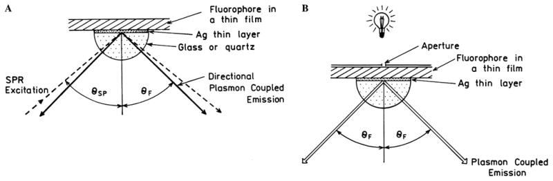
(A) Surface plasmon-coupled emission with excitation by the evanescent wave (Kretschmann configuration) and (B) from the side opposite the prism (reverse Kretschmann configuration).
Suppose the sample is excited from the side opposite the prism which is called the “reverse Kretschmann” configuration. This mode of excitation is shown in Fig. 11B where a small spot is illuminated by a light source and a small aperture in a spatial filter. In this case the incident light would not create surface plasmons and there is no evanescent field due to the incident light. An excited fluorophore near the metal film would not know how it was excited; that is, the emission should be the same whether the fluorophore is excited by evanescent SPR field (Fig. 11A) or from a light source not coupled to the surface plasmon (Fig. 11B). In the reverse Kretschmann configuration the fluorophores will be excited uniformly across the thickness of the sample. However, only those fluorophores within a fractional wavelength distant from the metal will couple to the surface and result in SPCE. This allows the use of SPCE without the surface plasmon excitation, which can simplify the devices based on this phenomenon. Since fluorophores distant from the metal will not couple, autofluorescence from molecules not localized by the surface chemistry should be suppressed.
Consider excitation from the sample phase (Fig. 11B). Since the fluorophore emits without remembering its source of excitation, there is no plane of incidence for the plasmon-coupled emission. The SPCE will be the same for all azimuthal angles (θA) around the z axis. Suppose the prism is a hemisphere rather than a hemicylinder (Fig. 12). The emission seen looking along the z axis will appear as a cone at angle θF with an equal distribution of emission at all angles θA. Additionally, different emission wavelengths will appear at different cone angles; that is, a multicolor sample will display a rainbow-like pattern (Fig. 13A) with the longer wavelength being inside the shorter wavelengths.
Fig. 12.

Surface plasmon-coupled cone of emission for fluorophores near a metallic film.
Fig. 13.

Cone of SPCE as seen from its central z axis. (A) Wavelength distribution not drawn to scale. (B) p-polarization of SPCE.
Plasmon-coupled emission is expected to display interesting polarization properties. Recall that SPR occurs only for the p-polarized component of the incident light because the interaction of the electric field with the metal plane depends on the incident angle. Similarly, only the p-polarized components of the emission are expected to couple with the surface plasmons. Hence, the polarization of the cone will always point away from the normal z axis (Fig. 13B), that is the SPCE will be p-polarized at all angles around the cone, independently of the mode of excitation. The SPCE will remain p-polarized whether the sample is fluid or solid, that is, whether or not the polarization of the free-space emission of the sample is low or high. We note that the coupling efficiency with the surface plasmons will depend on fluorophore orientations relative to the metal surface. For preciseness we note that some dipoles with the s orientation may couple into the plasmon, but much more weakly. It is not clear whether this smaller amount of coupled emission will be s- or p-polarized in the prism.
Theoretical and experimental studies of plasmon-coupled emission
There are a considerable number of publications on the theoretical aspects of fluorophores interacting with metallic surfaces or mirrors [68–70]. This theory is complex, mostly focused on thick metal films or mirrors, and difficult to correlate with experimental expectations. There appear to be three types of interactions of fluorophores with smooth metal surfaces [68]. These processes are shown in Fig. 14 as the relative decay rates at a distance d from a silver surface (γ(d)) as compared to the rate for the same process in free space (γ(∞)) at infinite distance from the metal. If the fluorophore is close to the surface (d < 20 nm) there is a high rate for radiationless deactivation and the emission is quenched (....). The silver surface has modest effects on the radiative decay rate at distances up to 200 nm. Depending on the orientation, the reflected field can increase or decrease the rate of emission. At distances from 20 to 100 nm, the dominant decay rate for the perpendicular (⊥) dipole is into the surface plasmon. For a parallel (||) dipole closer than 100 nm, the radiative rate (– – –) is decreased because the oscillatory charge in the fluorophore is partially cancelled by opposite charges on the metal surface. For perpendicular (⊥) dipoles the oscillating charge on the fluorophore and in the metal create dipoles with the same orientation. The net dipole is increased and the radiative rate (– – –) increases.
Fig. 14.

Normalized decay rates for quenching (....), SPCE (—), and free-space emission (– – –); || and ⊥ refer to the dipole orientations relative to the metal surface. Normalization is relative to the free-space decay rate for each process. Calculated for 633 nm. Revised from [68].
We are interested in the fraction of the potential fluorescence that results in SPCE. Fig. 14 shows that SPCE should be observable for any fluorophores that are not quenched, typically those at least 1 nm from the metal surface. In the range from 10 to 500 nm decay will occur by both plasmon coupling and emission.
It is interesting to examine the relative probability of the fluorophore decaying by each quenching (....), emission (– – –), or coupling to surface plasmons (—) (Fig. 15). At distances below 20 nm quenching is most probable and above 500 nm the free-space emission is dominant. At a distance near 200 nm (≈λ/2) the parallel dipoles show increased free-space emission and the perpendicular dipoles show decreased free-space emission. This distance dependence results in the oscillatory behavior reported for fluorophores in front of mirrors [71].
Fig. 15.

Distance-dependent interactions of a fluorophore with a metallic surface. Revised from [68]. || and ⊥ refer to a dipole parallel to or perpendicular to the surface, respectively. Quenching (....), SPCE (—), and free-space emission (– – –) to 633 nm.
SPCE occurs at distances beyond the range of quenching but close enough to the mirror for the dipoles to interact with the metal (Fig. 15, —). The maximum amount of SPCE occurs from 20 to 200 nm for the perpendicular dipoles. Coupling of the parallel dipoles is much weaker than that of perpendicular dipoles. The fact that SPCE occurs over longer distances from the surface than quenching suggests that gold films can also be used to couple emission into the prism. Forster transfer to the gold surface is likely to be minimal at distances of 100–200 nm where SPCE is still efficient. Gold is more inert than silver which may be advantageous for the applications of SPCE.
An important property of SPCE is a unique dependence on dipole orientation relative to the surface. The orientation dependence for SPCE is opposite that for quenching or emission into free space. That is, SPCE occurs more favorably for perpendicular dipoles. Quenching and emission into free space occur preferentially for parallel dipoles. This suggests that the fabrication of samples with dipoles perpendicular to the surface will result in highly efficient plasmon coupling of the dipoles into the prism. The probability of SPCE is highest when the fluorophore is beyond the distance for quenching (>20 nm) and closer to the surface than 500 nm (Fig. 15). The interaction between the fluorophores and the metal is a near-field nonradiative interaction. The radiation that couples into the prism is due to the surface plasmon in the metal and not in the fluorophore. The decay probability via the plasmons is higher for a dipole perpendicular to the surface than for a parallel dipole. This selectivity for perpendicular dipoles is the result of the required p-polarization for SPR. Dipoles oriented perpendicular to the surface have an electric field with p-polarization. Coupling to the surface occurs over a large range of distances, 20–500 nm (Fig. 15), which is the depth of the evanescent wave in SPRA. This is important for the applications of SPCE because coupling will occur over a significant volume in the sample, allowing detection of lower overall analyte concentrations.
Relatively little information about the nonradiative pathways where the fluorophore itself is not radiating is available. Fluorophores are known to be quenched when placed on metallic surfaces [72–75], but it is difficult to identify mechanisms without observable emission. Little information about coupling to the surface plasmons in thick metal samples is available because there is no way to observe the plasmons in the opaque metal. Recall that a surface plasmon cannot be excited from the low-refractive-index side because of an inability to match the surface wavevectors. Similarly, the surface plasmon modes of a thick metal cannot emit into the media. Hence any energy which couples from a fluorophore to a thick metal is dissipated by nonradiative processes.
Surface plasmon-coupled emission can be observed using the Kretschmann configuration and a prism to couple the excited fluorophore into a plasmon and then into radiation. Several experimental papers have appeared on this topic [76–81]. These papers show that emission can couple through a thin silver surface into the prism. Some of these papers show that the emission occurs only at the surface plasmon angle, with the earliest report appearing in 1975 [82]. One of these experiments was described in our earlier article on radiative decay engineering [18], which showed angle-dependent emission from rhodamine near a silver-coated hemicylinder [77]. It is instructive to describe this early report on SPCE which appeared in 1979. In these experiments emission was observed using photographic plates to measure the angular distributions of the intensities (Fig. 16). A rhodamine solution was excited through a prism at θSP. The emission was then passed through a filter to select the wavelength and imaged on photographic plates. These plates are shown schematically in Fig. 16. The spot toward the left is due to reflected 514-nm light which passed through filters which did not completely remove the incident wavelength. Without a wavelength-selective filter, there is a wide angular distribution of the emission (top rectangular panel). The angular distribution is considerably more narrow when the emission is passed through narrow band filters (lower panels). The emission appears at a different location (angle) for each emission wavelength. The presence of different wavelength angles in the top panel was not evident because of the use of black-and-white film. This result shows the existence of SPCE and confirms the possibility of intrinsic spectral resolution with SPCE.
Fig. 16.

Early detection of surface plasmon-coupled emission. The vertical lines indicate emission observed on the photographic plates. From [77].
Many applications of fluorescence technology depend on high sensitivity; so it is important to determine the efficiency of coupling into the plasmons. Fig. 17 shows calculations of the probability of coupling to the surface plasmons for fluorophores at various distances above a silver film [76]. This calculation does not reveal the fraction of the coupled energy that will appear as far-field radiation. However, since SPCE through thin films occurs [77], the coupling efficiency will indicate the potential collection efficiencies of SPCE. Remarkably, a dipole perpendicular to the surface and 120 nm from the surface has a 93% probability of coupling to the plasmons. Parallel dipoles couple more weakly with the surface plasmons and this coupling occurs at shorter distances near 200 nm. When averaged over all orientations the coupling efficiency can be over 60% for randomly oriented fluorophores 20 nm above the surface. This suggest the possibility of capturing over 50% of the emission with simple optical configurations. Efficient light collection can result in considerably increased sensitivity. A typical fluorescence experiment may use a 1-inch lens 3 or more inches from the sample. For isotropic emission this lens would collect about 1% of the light. As will be shown below, SPCE can be used in geometries that direct essentially all the light to a detector. Hence, the use of SPCE can result in a 50-fold increase in collection efficiency and sensitivity. If the sample is excited by the evanescent field, then the effective illumination intensity is increased 10- to 40-fold, providing an overall increase of up to 1000-fold for SPCE.
Fig. 17.

Probability of surface plasmon-coupled emission for a fluorophore above a silver film. From [76].
Applications of surface plasmon-coupled emission
We see numerous potential applications of SPCE, particularly in biotechnology and environmental and medical sensing. The experimental configurations useful for SPCE can be very similar to that used for SPRA. These SPRA instruments use thin gold films, scan the angle of incidence, and measure the angle-dependent reflectivity. This approach is similar to measurement of the angle-dependent plasmon-coupled emission. The angular resolution of SPRA devices is far greater than needed for SPCE. If a SPRA instrument scans the angle of incidence, then for SPCE, the excitation and detection channels may be exchanged to allow for excitation at θSP scanning the observation angle. Hence it seems possible that SPCE could become an additional or alternative mode of operation for SPRA instruments.
We now describe some potential advantages and configurations for the applications of SPCE. An important possibility with SPCE is rejection of background emission. Consider a sample in which the fluorophores of interest are located within 200 nm of the metal surface (Fig. 18). In an actual application this localization would be accomplished by adsorbing or conjugating biomolecules to the surface. Assume the sample is excited from above the sample in the reverse Kretschmann configuration. In this configuration the fluorophores are excited almost uniformly through the thickness of the sample. If the emission is observed from above the sample then the 600-nm background will dominate the emission (...., bottom). If the plasmon-coupled emission is observed the signal will be enriched for the 500-nm emission of interest because only fluorophore near the metal will couple efficiently into the prism (– – –). More selective observation of fluorophores near the metal surface can be accomplished using the Kretschmann configuration. If the sample is excited through the prism at θSP then the fluorophores of interest will be selectively excited by the evanescent field which penetrates about λ/2 into the sample, further increasing the desired 500-nm emission and suppressing the background 600-nm emission. The evanescent field is increased about 40-fold relative to the incident field which will further increase the selective observation of fluorophores near the metal surface.
Fig. 18.

Suppression of background emission by observation of the plasmon-coupled emission.
Another approach to using SPCE is to take advantage of the intrinsic angular shifts for different wavelengths. This property of SPCE can be used to provide approaches to wavelength-ratiometric measurements. Consider a triangular prism coupled to the sample with a silver film (Fig. 19). The sample can be excited with θSP to obtain an enhanced localized field in the sample. The intensity of the excitation source or the reflectivity could be observed on the opposite side in the plane of incidence. Two additional detectors can be positioned at the two 90° angles and the desired wavelengths selected with filters. This configuration would provide simultaneous measurement of three signals and efficient collection of the emission due to plasmon coupling. The prisms could be as small as needed for the desired application. Multiple prisms could be placed on the substrate for high-throughput or multianalyte measurements. The faces of the pyramids could be shaped to direct the SPCE toward a detector.
Fig. 19.

Configuration for wavelength-ratiometric measurement using SPCE.
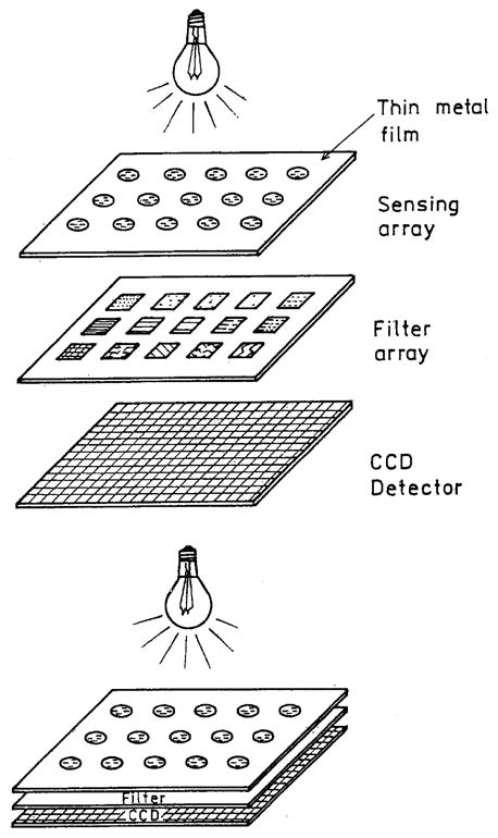
SPCE may also be useful with arrays of the type being used in genomics or proteomics (Fig. 20). The only required change to the array will be the addition of a thin metal film. The entire array could be illuminated in the reverse Kretschmann configuration. Each spot on the array would couple through the metal; they can be observed through different emission filters and then recorded on a CCD detector. Proximity focusing would result in an efficient and compact device. Additionally, the metal films used for SPCE are highly reflective which would prevent most of the incident light from reaching the detector. The spots may need to be further apart than those in high-density DNA arrays because of the cone of emission and propagation of plasmon across the surface.
Fig. 20.
Collection of emission from an array using plasmon-coupled emission.
Plasmon-coupled emission can also be used to collect emission spectrum simultaneously at all wavelengths. Suppose a large sample area is illuminated on the reverse Kretschmann configurations (Fig. 21). The emission could be coupled through a variable-wavelength filter and then to a CCD or linear array detector. These configurations would provide both high-efficiency collection and simultaneous observation at all wavelengths. While different wavelengths have different coupling angles, the angular shifts are only a couple of degrees. The variable wavelength filter needs to be thin to allow proximity focusing of the different wavelengths, or it may be useful to add a translucent sheet to stop lateral migration of the coupled emission. Of course the configuration shown in Fig. 21 would work with a metal film. The directional nature of SPCE makes it possible to use dispersive optics without focusing lenses (Fig. 22). The SPCE could be passed through a prism, separating the wavelengths, and then observed using a linear array detector.
Fig. 21.
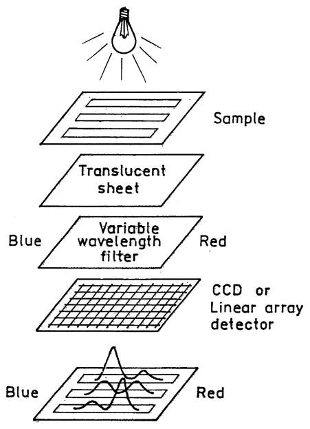
Proximity-focused spectrofluorometer using a variable-wavelength emission filter.
Fig. 22.

Prism spectrofluorometer using surface plasmon-coupled emission.
In the previous schematic (Fig. 22) we used a prism to increase the angular difference between emission wavelengths. This was suggested because the angular separation for various wavelengths for SPCE is modest, about 3° from 500 to 700 nm for silver (Fig. 7). Another approach is to provide larger angular differences across typical emission spectra. In contrast to planar silver surfaces which quench fluorescence, periodic silver surfaces can facilitate emission by nearby fluorophores. Fluorescence has been observed from fluorophores directly on or close to silver grating [83–86]. The silver surfaces were about 200 nm thick so the gratings were opaque. The periodic structure on the gratings provides another mechanism to match the need for wavevector matching at the interface, making it possible to excite plasmon in metallic gratings from air. In fact, such plasmons are the origin of the Wood’s anomaly in which gratings become nonreflective at a particular wavelength. Since the periodic structure provides a mechanism for coupling incident light into surface plasmons, it should also provide a mechanism for coupling the energy of the excited fluorophores into radiation.
Suppose the sample is on a opaque silver grating with a pitch of λG = 600 nm. The condition for plasmon resonance is now given by
| (15) |
where n is an integer and G is the propagation constant of the grating, G = 2π/λG. The superscripts G and M refer to a grating and planar surface, respectively. Recalling that k0 = 2π/λ0 this expression can be rewritten as
| (16) |
The presence of the additional term has a dramatic effect on the angles for coupling to the plasmon to different wavelengths. Assume the grating is silver and θSP for a planar surface is 50°. One can readily calculate that θSP for 500 nm is now near 2° (Fig. 23). Emission at 600 and 700 nm will appear at 16° and 28° from the normal, respectively. Hence one could readily collect an emission spectrum with an array detector (Fig. 23).
Fig. 23.

Emission wavelength separation with grating-coupled emission.
In the previous paragraphs we consider described methods to use the wavelength dependence of SPCE. It is also valuable to consider how SPCE can be used for high-sensitivity detection. Several possibilities are shown in Fig. 24. The most direct approach is to collect the SPCE with an appropriately sized lens. Because of the large angles for SPCE it is probably preferable to use two optical elements rather than one larger lens. Essentially all the emission could be focused on the detector. A single optical element shaped like a hexagon could accomplish the same task using TIR of the coupled emission. This element could be simplified further using a hemisphere with the sample located on the spherical surface. And finally, light collection and focusing onto the detector could be accomplished with no free-space optics using a glass sphere (Fig. 24B). In all these configurations the excitation can occur from the sample side, outside the optical element, or by the surface plasmon evanescent wave.
Fig. 24.

Potential geometries for efficient collection of SPCE.
Another approach to obtain high sensitivity would be to use a silver-coated fiber (not shown). If the surface chemistry is located on the silver the desired signal could be obtained even in samples displaying high autofluorescence. Only emission from within λ/2 of the metal surface would be collected by SPCE. Excitation could be accomplished from within the fiber or from an external source. It is even possible to imagine the use of ambient light for excitation.
High-sensitivity detection is often accomplished with methods that do not result in light-induced background signals. These methods include chemiluminescence (CL), bioluminescence (BL), and electrochemiluminescence (ECL) [87–91]. Since SPCE does not depend on the mode of excitation, SPCE will also occur for these nonphotoluminescent phenomena. For example, the enzymes needed for CL or BL could be localized near the metal film, resulting in high collection efficiency for the generated emission. Similarly, for ECL, the metal film could be used to both initiate the ECL reaction and couple the emission into the prism. Of course the metallic electrodes will have to display adequate chemical stability or be coated to protect the surfaces.
In summary we believe that surface plasmon-coupled emission provides a new approach to the design of devices for sensing, biotechnology, and medical applications. SPCE can be used in a wide variety of formats that provide simple and robust systems. In the companion paper [67] we provide experimental demonstrations of surface plasmon-coupled emission.
Acknowledgments
This work was supported by the NIH National Center for Research Resource, RR-08119, HG-002655, EB-000682, and EB-00981. The author thanks Drs. Z. Gryczynski, I. Gryczynski, and W. Barnes for their helpful discussions and K. Nowaczyk for calculations of the surface plasmon angles.
Footnotes
Abbreviations used: SPCE, surface plasmon-coupled emission; SPR, surface plasmon resonance; SPRA, SPR analysis; TIR, total internal reflectance; PVA, polyvinyl alcohol; BSA, bovine serum albumin; CCD, charge-coupled device; CL, chemiluminescence; BL, bioluminesence; ELC, electrochemiluminesence.
References
- 1.Gosling JP. A decade of development in immunoassay methodology. Cell. 1990;36:1408–1427. [PubMed] [Google Scholar]
- 2.Walker NJ. A technique whose time has come. Science. 2002;296:557–559. doi: 10.1126/science.296.5567.557. [DOI] [PubMed] [Google Scholar]
- 3.White JC, Stryer L. Photostability studies of phycobiliprotein fluorescent labels. Anal Biochem. 1987;161:442–452. doi: 10.1016/0003-2697(87)90473-8. [DOI] [PubMed] [Google Scholar]
- 4.Kronick MN. The use of phycobiliproteins as fluorescent labels in immunoassays. J Immunol Methods. 1986;92:1–13. doi: 10.1016/0022-1759(86)90496-5. [DOI] [PubMed] [Google Scholar]
- 5.Daehne S, Resch-Genger U, Wolfbeis OS. Near-Infrared Dyes for High Technology Applications. Kluwer Academic Publishers; New York: 1998. p. 458. [Google Scholar]
- 6.Casay GA, Shealy DB, Patonay G. Near-infrared fluorescence probes. In: Lakowicz JR, editor. Topics in Fluorescence Spectroscopy, vol. 4: Probe Design and Chemical Sensing. Plenum Press; New York: 1994. pp. 183–222. [Google Scholar]
- 7.Diamandis EP. Immunoassays with time-resolved fluorescence spectroscopy: principles and applications. Clin Biochem. 1988;21:139–150. doi: 10.1016/0009-9120(88)90001-x. [DOI] [PubMed] [Google Scholar]
- 8.Lövgren T, Pettersson K. Time-resolved fluoroimmunoassay, advantages and limitations. In: Van Dyke K, Van Dyke R, editors. Luminescence Immunoassay and Molecular Applications. CRC Press; New York: 1990. pp. 234–250. [Google Scholar]
- 9.Strickler SJ, Berg RA. Relationship between absorption intensity and fluorescence lifetimes of molecules. J Chem Phys. 1962;37:814–822. [Google Scholar]
- 10.Lieberherr M, Fattinger Ch, Lukosz W. Optical-environment-dependent effects on the fluorescence of submonomolecular dye layers on interfaces. Surface Sci. 1987;189/190:954–959. [Google Scholar]
- 11.Toptygin D, Savtchenko RS, Meadow ND, Roseman S, Brand L. Effect of the solvent refractive index on the excited-state lifetime of a single-tryptophan residue in a protein. J Phys Chem B. 2002;106:3724–3734. [Google Scholar]
- 12.Lukosz W, Kunz RE. Changes in fluorescence lifetimes induced by variation of the radiating molecules optical environment. Opt Commun. 1979;31(1):42–46. [Google Scholar]
- 13.Dhexhage KH. Interaction of light with monomolecular dye lasers. In: Wolfe E, editor. Progress in Optics. North Holland: Amsterdam; 1974. pp. 161–232. [Google Scholar]
- 14.Amos RM, Barnes WL. Modification of the spontaneous emission rate of Eu3+ ions close to a thin metal mirror. Phys Rev B. 1997;55(11):7249–7254. [Google Scholar]
- 15.Hinds EA. Cavity quantum electrodynamics. Adv At Mol Opt Phys. 1991;28:237–289. [Google Scholar]
- 16.Haroche S, Kleppner D. Cavity quantum electrodynamics. Phys Today. 1989:24–30. [Google Scholar]
- 17.Haroche S, Raimond J-M. Cavity quantum electrodynamics. Sci Am. 1993:54–62. [Google Scholar]
- 18.Lakowicz JR. Radiative decay engineering: biophysical and biomedical applications. Appl Biochem. 2001;2981:1–24. doi: 10.1006/abio.2001.5377. [DOI] [PMC free article] [PubMed] [Google Scholar]
- 19.Lakowicz JR, Shen Y, D’Auria S, Malicka J, Gryczynski Z, Gryczynski I. Radiative decay engineering 2: effects of silver island films on fluorescence intensity, lifetimes and resonance energy transfer. Anal Biochem. 2002;301:261–277. doi: 10.1006/abio.2001.5503. [DOI] [PMC free article] [PubMed] [Google Scholar]
- 20.Lakowicz JR, Gryczynski I, Shen Y, Malicka J, Gryczynski Z. Intensified fluorescence. Photon Spectra. 2001:96–104. [Google Scholar]
- 21.Lakowicz JR, Malicka J, Gryczynski I. Silver particles enhance the emission of fluorescent DNA oligomers. BioTechniques. 2003;34:62–68. doi: 10.2144/03341st01. [DOI] [PMC free article] [PubMed] [Google Scholar]
- 22.Malicka J, Gryczynski I, Fang J, Lakowicz JR. Fluorescence spectral properties of cyanine dye-labeled DNA oligomers on surfaces coated with silver particles. Anal Biochem. 2003;317:136–146. doi: 10.1016/S0003-2697(03)00005-8. [DOI] [PMC free article] [PubMed] [Google Scholar]
- 23.Lakowicz JR, Malicka J, D’Auria S, Gryczynski I. Release of the self-quenching of fluorescence near silver metallic surfaces. Anal Biochem. 2003;320:13–20. doi: 10.1016/S0003-2697(03)00351-8. [DOI] [PMC free article] [PubMed] [Google Scholar]
- 24.Malicka J, Gryczynski I, Lakowicz JR. Enhanced emission of highly labeled DNA oligomers near silver metallic surfaces. Anal Chem. 2003;75:4408–4414. doi: 10.1021/ac020739m. [DOI] [PMC free article] [PubMed] [Google Scholar]
- 25.Parfenov A, Gryczynski I, Malicka J, Geddes CD, Lakowicz JR. Enhanced fluorescence from fluorophores on fractal silver surfaces. J Phys Chem B. 2003;107:8829–8833. doi: 10.1021/jp022660r. [DOI] [PMC free article] [PubMed] [Google Scholar]
- 26.Geddes CD, Parfenov A, Lakowicz JR. Photodeposition of silver can result in metal-enhanced fluorescence. Appl Spectrosc. 2003;57:526–531. doi: 10.1366/000370203321666542. [DOI] [PMC free article] [PubMed] [Google Scholar]
- 27.Ambrose WP, Goodwin PM, Jett JH, Van Orden A, Wemer JH, Keller RA. Single molecule fluorescence spectroscopy at ambient temperature. Chem Rev. 1999;99:2929–2956. doi: 10.1021/cr980132z. [DOI] [PubMed] [Google Scholar]
- 28.Soper SA, Nutter HL, Keller RA, Davis LM, Shera EB. The photophysical constants of several fluorescent dyes pertaining to ultrasensitive fluorescence spectroscopy. Photochem Photobiol. 1993;57(6):972–977. [Google Scholar]
- 29.Van Orden A, Machara NP, Goodwin PM, Keller RA. Single-molecule identification in flowing sample streams by fluorescence burst size and intraburst fluorescence decay rate. Anal Chem. 1998;70(7):1444–1451. doi: 10.1021/ac970545k. [DOI] [PubMed] [Google Scholar]
- 30.Schmidt Th, Schutz GJ, Baumgartner W, Gruber HJ, Schindler H. Characterization of photophysics and mobility of single molecules in a fluid lipid membrane. J Phys Chem. 1995;99:17662–17668. [Google Scholar]
- 31.Köhn F, Hofkens J, Gronheid R, Van der Auweraer M, DeSchryver FC. Parameters influencing the on- and off-times in the fluorescence intensity traces of single cyanine dye molecules. J Phys Chem A. 2002;106:4808–4814. [Google Scholar]
- 32.Salamon Z, Macleod HA, Tollin G. Surface plasmon resonance spectroscopy as a tool for investigating the biochemical and biophysical properties of membrane protein systems. I: Theoretical principles. Biochim Biophy Acta. 1997;1331:117–129. doi: 10.1016/s0304-4157(97)00004-x. [DOI] [PubMed] [Google Scholar]
- 33.Melendez J, Carr R, Bartholomew DU, Kukanskis K, Elkind J, Yee S, Furlong C, Woodbury R. A commercial solution for surface plasmon sensing. Sensor Actuat B. 1996;35–36:212–216. [Google Scholar]
- 34.Liedberg B, Lundstrom I. Principles of biosensing with an extended coupling matrix and surface plasmon resonance. Sensor Actuat B. 1993;11:63–72. [Google Scholar]
- 35.Cooper MA. Optical biosensors in drug discovery. Nat Rev. 2002;1:515–528. doi: 10.1038/nrd838. [DOI] [PubMed] [Google Scholar]
- 36.Wegner GJ, Lee HJ, Corn RM. Characterization and optimization of peptide arrays for the study of epitope-antibody interactions using surface plasmon resonance imaging. Anal Chem. 2002;74:5161–5168. doi: 10.1021/ac025922u. [DOI] [PubMed] [Google Scholar]
- 37.Frutos AG, Corn RM. SPR of utrathin organic films. Anal Chem. 1998:449A–455A. [Google Scholar]
- 38.Jordan CE, Frey BL, Kornguth S, Corn RM. Characterization of Poly-L-lysine adsorption onto alkanethiol-modified gold surfaces with polarization- modulation fourier transform infrared spectroscopy and surface plasmon resonance measurements. Langmuir. 1994;10:3642–3648. [Google Scholar]
- 39.Frey BL, Jordan CE, Kornguth S, Corn RM. Control of the specific adsorption of proteins onto gold surfaces with poly(L-lysine) monolayers. Anal Chem. 1995;67:4452–4457. [Google Scholar]
- 40.Axelrod D, Hellen EH, Fulbright RM. Total internal reflection fluorescence. In: Lakowicz JR, editor. Topics in Fluorescence Spectroscopy, vol. 3: Biochemical Applications. Plenum Press; New York: 1992. pp. 289–343. [Google Scholar]
- 41.Neumann T, Johansson ML, Kambhampati D, Knoll W. Surface-plasmon fluorescence spectroscopy. Adv Funct Mater. 2002;12(9):575–586. [Google Scholar]
- 42.Liebermann T, Knoll W. Surface-plasmon field-enhanced fluorescence spectroscopy. Colloid Surface. 2000;171:115–130. [Google Scholar]
- 43.Attridge JW, Daniels PB, Deacon JK, Robinson GA, Davidson GP. Sensitivity enhancement of optical immunosensors by the use of a surface plasmon resonance fluoroimmunoassay. Biosens Bioelectron. 1991;6:201–214. doi: 10.1016/0956-5663(91)80005-i. [DOI] [PubMed] [Google Scholar]
- 44.Liebermann T, Knoll W, Sluka P, Herrmann R. Complement hybridization from solution to surface-attached probe-oligonucleotides observed by surface-plasmon-field-enhanced fluorescence spectroscopy. Colloid Surface. 2000;169:337–350. [Google Scholar]
- 45.Fukuda N, Mitsuishi M, Aoki A, Miyashita T. Photocurrent enhancement for polymer Langmuir–Blodgett monolayers containing ruthenium complex by surface plasmon resonance. J Phys Chem B. 2002;106:7048–7052. [Google Scholar]
- 46.Attridge JW, Daniels PB, Deacon JK, Robinson GA, Davidson GP. Sensitivity enhancement of optical immunosensors by the use of a surface plasmon resonance fluoroimmunoassay. Biosens Bioelectron. 1991;6:201–214. doi: 10.1016/0956-5663(91)80005-i. [DOI] [PubMed] [Google Scholar]
- 47.Natan MJ, Lyon LA. Surface plasmon resonance biosensing with colloidal Au amplification. In: Feldheim DL, Foss CA, editors. Metal Nanoparticles: Synthesis, Characterization, and Applications. Marcel Dekker; New York: 2002. pp. 183–205. [Google Scholar]
- 48.Malmqvist M. BIACORE: an affinity biosensor system for characterization of biomolecular interactions. Biochem Soc Trans. 1999;27:335–340. doi: 10.1042/bst0270335. [DOI] [PubMed] [Google Scholar]
- 49.Gestwicki JE, Hsieh HV, Pitner JB. Using receptor conformational change to detect low molecular weight analytes by surface plasmon resonance. Anal Chem. 2001;73:5732–5737. doi: 10.1021/ac0105888. [DOI] [PubMed] [Google Scholar]
- 50.Hendrix M, Priestley ES, Joyce GF, Wong CH. Direct observation of aminoglycoside–RNA interactions by surface plasmon resonance. J Am Chem Soc. 1997;119(16):3636–3648. doi: 10.1021/ja964290o. [DOI] [PubMed] [Google Scholar]
- 51.Woodbury RG, Wendin C, Clendenning J, Melendez J, Elkind J, Bartholomew D, Brown S, Furlong CE. Construction of biosensors using a gold-binding polypeptide and a miniature integrated surface plasmon resonance sensor. Biosens Bioelectron. 1997;13:1117–1126. doi: 10.1016/s0956-5663(98)00060-8. [DOI] [PubMed] [Google Scholar]
- 52.Kolomenskii AA, Gershon PD, Schuessler HA. Sensitivity and detection limit of concentration and adsorption measurements by laser-induced surface-plasmon resonance. Appl Opt. 1997;36(25):6539–6547. doi: 10.1364/ao.36.006539. [DOI] [PubMed] [Google Scholar]
- 53.Sambles JR, Bradbery GW, Yang F. Optical excitation of surface plasmons: an introduction. Contemp Phys. 1991;32:173–183. 3–. [Google Scholar]
- 54.Levi L. A Guide to Optical System Design. Vol. 1. Wiley; New York: 1968. Applied Optics; p. 620. [Google Scholar]
- 55.Born M, Wolf E. Electromagnetic Theory of Propagation, Interference and Diffraction of Light. Pergamon Press; New York: 1980. Principles of Optics; p. 808. [Google Scholar]
- 56.Crawford FS., Jr . Waves. McGraw-Hill Publishers; New York: 1968. p. 600. [Google Scholar]
- 57.Feldheim DL, Foss CA., Jr . Synthesis, Characterization, and Applications, Metal Nanoparticles. Marcel Dekker; New York: 2002. Overview; pp. 1–15. [Google Scholar]
- 58.Johnson BP, Christy RW. Optical constants of the noble metals. Rev B Condens Matter. 1972;6:4370. [Google Scholar]
- 59.Born M, Wolf E. Interference and Diffraction of Light. Pergamon Press; New York: 1980. Principles of Optics. Electromagnetic Theory of Propagation; p. 808. [Google Scholar]
- 60.Yguerabide J, Yguerabide EE. Light-scattering submicroscopic particles as highly fluorescent analogs and their use as tracer labels in clinical and biological applications. Anal Biochem. 1998;262:137–156. doi: 10.1006/abio.1998.2759. [DOI] [PubMed] [Google Scholar]
- 61.Pockrand I. Surface plasma oscillations at silver surfaces with thin transparent and absorbing coatings. Surf Sci. 1978;72:577–588. [Google Scholar]
- 62.Kurihara K, Suzuki K. Theoretical understanding of an absorption-based surface plasmon resonance sensor based on Kretschmannn’s theory. Anal Chem. 2002;74:696–701. doi: 10.1021/ac010820+. [DOI] [PubMed] [Google Scholar]
- 63.Salamon Z, Macleod HA, Tollin G. Surface plasmon resonance spectroscopy as a tool for investigating the biochemical and biophysical properties of membrane protein systems. I: Theoretical principles. Biochim Biophys Acta. 1997;1331:117–129. doi: 10.1016/s0304-4157(97)00004-x. [DOI] [PubMed] [Google Scholar]
- 64.Homola J, Koudela I, Yee SS. Surface plasmon resonance sensors based on diffraction gratings and prism couplers: sensitivity comparison. Sensor Actuat B. 1999;54:16–24. [Google Scholar]
- 65.Brockman JM, Nelson BP, Corn RM. Surface plasmon resonance imaging measurements of ultrathin organic films. Annu Rev Phys Chem. 2000;51:41–63. doi: 10.1146/annurev.physchem.51.1.41. [DOI] [PubMed] [Google Scholar]
- 66.Nelson BP, Frutos AG, Brockman JM, Corn RM. Near-infrared surface plasmon resonance measurements of ultrathin films. 1. Angle shift and SPR imaging experiments. Anal Chem. 1999;71:3928–3934. [Google Scholar]
- 67.Gryczynski I, Malicka J, Lakowicz JR. Radiative decay engineering 4. Experimental studies of surface plasmon-coupled emission. Anal Biochem. 2004 doi: 10.1016/j.ab.2003.09.036. in this issue. [DOI] [PMC free article] [PubMed] [Google Scholar]
- 68.Ford GW, Weber WB, editors. Electromagnetic Interactions of Molecules With Metal Surfaces. Vol. 113. North-Holland Physics Publishing; Amsterdam: 1984. pp. 195–287. [Google Scholar]
- 69.Chance RR, Prock A, Silbey R. Molecular fluorescence and energy transfer near interfaces. Adv Chem Phys. 1978;37:1–65. [Google Scholar]
- 70.Barnes WL. Fluorescence near interfaces: the role of photonic mode density. J Mod Opt. 1998;45(4):661–699. [Google Scholar]
- 71.Drexhage KH. Influence of a dielectric interface on fluorescence decay time. J Luminescence. 1970;1–2:693–701. [Google Scholar]
- 72.Cnossen G, Drabe KE, Wiersma DA. Fluorescence properties of submonolayers of rhodamine 6G in front of a mirror. J Chem Phys. 1993;98:5276–5281. [Google Scholar]
- 73.Shu QQ, Hansma PK. Fluorescent apparent quantum yields for excited molecules near dielectric interfaces. Thin Solid Films. 2001;384:76–84. [Google Scholar]
- 74.Campion A, Gallo AR, Harris CB, Robota HJ, Whitmore PM. Electronic energy transfer to metal surfaces: a test of classical image dipole theory at short distances. Chem Phys Lett. 1980;73(3):447–450. [Google Scholar]
- 75.Daffertshofer M, Port H, Wolf HC. Fluorescence quenching of ultrathin anthracene films by dielectric and metallic substrates. Chem Phys. 1995;200:225–233. [Google Scholar]
- 76.Weber WH, Eagen CF. Energy transfer from an excited dye molecule to the surface plasmons of an adjacent metal. Opt Lett. 1979;4(8):236–238. doi: 10.1364/ol.4.000236. [DOI] [PubMed] [Google Scholar]
- 77.Benner RE, Dornhaus R, Chang RK. Angular emission profiles of dye molecules excited by surface plasmon waves at a metal surface. Opt Commun. 1979;30(2):145–149. [Google Scholar]
- 78.Pockhand I, Brillante A, Mobius D. Nonradiative decay of molecular excitation at a metal interface. Nuovo Cimento. 1981;63:350–357. [Google Scholar]
- 79.Eagen CF, Weber WH, McCarthy CF, Terhune RW. Time-dependent decay of surface-plasmon-coupled molecular fluorescence. Chem Phys Lett. 1980;75(2):274–277. [Google Scholar]
- 80.Holland WR, Hall DG. Waveguide mode enhancement of molecular fluorescence. Opt Lett. 1985;10(8):414–416. doi: 10.1364/ol.10.000414. [DOI] [PubMed] [Google Scholar]
- 81.Shu QQ, Hansma PK. Fluorescent apparent quantum yields for excited molecules near dielectric interfaces. Thin Solid Films. 2001;384:76–84. [Google Scholar]
- 82.Gerbshtein YuM, Merkulov IA, Mirlin DN. Transfer of luminescence-center energy to surface plasmons. JETP Lett. 1975;22:35–36. [Google Scholar]
- 83.Sullivan KG, King O, Sigg C, Hall DG. Directional, enhanced fluorescence from molecules near a periodic surface. Appl Opt. 1994;33(13):2447–2454. doi: 10.1364/AO.33.002447. [DOI] [PubMed] [Google Scholar]
- 84.Kitson SC, Barnes WL, Sambles JR. Photoluminescence from dye molecules on silver gratings. Opt Commun. 1996;122:147–154. [Google Scholar]
- 85.Knoll W, Philpott MR, Swalen JD. Emission of light from Ag metal gratings coated with dye monolayer assemblies. J Chem Phys. 1981;75(10):4795–4799. [Google Scholar]
- 86.Amos RM, Barnes WL. Modification of spontaneous emission lifetimes in the presence of corrugated metallic surfaces. Phys Rev B. 1999;59(11):7708–7714. [Google Scholar]
- 87.Kricka LJ. Clinical and biochemical applications of luciferases and luciferins. Anal Biochem. 1988;175:14–21. doi: 10.1016/0003-2697(88)90354-5. [DOI] [PubMed] [Google Scholar]
- 88.Akhavan-Tafti H, Reddy LV, Siripurapu S, Schoenfelner BA, Handley RS, Schapp AP. Chemiluminescent detection of DNA in low- and medium-density arrays. Clin Chem. 1998;44(9):2065–2066. [PubMed] [Google Scholar]
- 89.Leong MML, Fox GR. Luminescent detection of immunodot and western blots. Methods Enzymol. 1990;184:442–451. [PubMed] [Google Scholar]
- 90.Chappelle EW, Picciolo GL, Deming JW. Determination of bacterial content in fluids. Methods Enzymol. 1978;57:65–72. [Google Scholar]
- 91.Bolton E, Richter MM. Light emission at electrodes: an electrochemiluminescence demonstration. J Chem Ed Chem. 2001;78(5):641–643. [Google Scholar]