Abstract
Successful artificial tissue scaffolds support regeneration by promoting cellular organization as well as appropriate mechanical and biological functionality. We have previously shown in vitro that 2-D substrates with micron-scale grooves (5 μm deep, 18 μm wide, with 12 μm spacing) can induce cell orientation and ECM alignment. Here, we have transferred this microtopography onto biodegradable polycaprolactone (PCL) thin films. We further developed a technique to layer these cellularized microtextured scaffolds into a 3-D tissue construct. A surface modification technique was used to attach photoreactive acrylate groups on the PCL scaffold surface onto which polyethylene glycol (PEG-DA) -diacrylate gel could be photopolymerized. PEG-DA serves as an adhesive layer between PCL scaffolds, resulting in a VSMC-seeded layered 3-D composite structure that is highly organized and structurally stable. The PCL surface modification chemistry was confirmed via XPS, and the maintenance of cell number and orientation on the modified PCL scaffolds was demonstrated using colorometric and imaging techniques. Cell number and orientation were also investigated after cells were cultured in the layered 3-D configuration. Such 3-D tissue mimics fabricated with precise cellular organization will enable the systematic testing of the effects of cellular orientation on the functional and mechanical properties of tissue engineered blood vessels.
Keywords: micropatterning, vascular smooth muscle cell orientation, scaffold engineering
Introduction
The structural organization of cells and extracellular matrix (ECM) in native tissues is crucial for proper function, particularly in load-bearing and muscular tissues [1]. Therefore, the development of strategies for growing tissues with precise structural features that can be controlled over multiple length scales will be crucial for the construction of engineered tissues that can adequately mimic the properties of native tissues. Several in vitro techniques have been investigated to achieve 2-D cellular and ECM arrangement similar to that found in vivo. Some of these techniques involve spatial and chemical cues while others rely on topographical cues [2]. Such studies have noted that the spatial arrangement of cells and ECM influences cell morphology, proliferation, differentiation, attachment and ECM remodeling [3–6]. Micropatterned substrates in particular have been shown to modulate VSMC behavior. For example, VSMCs constrained in collagen lanes have exhibited orientation, elongation and decreased proliferation [5]. ECM remodeling and deposition as well as cytoskeleton organization were also enhanced on grooved substrata [6]. Technologies to orient VSMCs and the resulting effects of orientation on VSMC behavior have the potential for fabricating highly organized tissues that can serve as adequate replacements for diseased of damaged native tissues.
While studies in 2-D are informative, ultimately, one must be able to fabricate 3-D structures. Complex and controlled architectures are often a necessary alternative to seeding cells randomly on a porous scaffold, as control over structure is critical for gaining adequate tissue function. Recent novel techniques have been reported for achieving these complex architectures, however, most of these techniques result in scaffolding with features on the order of hundreds of microns [7]. To create complex 3-D architectures with smaller features, several groups have investigated the layering of micropatterned 2-D membranes to build up a 3-D scaffold [8–10]. Because these layering techniques require the assembly of the 3-D scaffold prior to cell seeding, the spatial resolution of the presented micropattern is again limited because cell seeding can occur only via the voids left open by the incorporated microtopography.
Here we focus on translating techniques that organize VSMCs in 2-D to 3-D and, to that end, have developed a novel technique to fabricate 3-D tissue constructs that incorporate micron-scale topographical cues to orient VSMCs. We layered micropatterned 2-D scaffolds to form a cohesive 3-D construct using adhesive layers between the PCL scaffolds. Thin microgrooved 2-D biodegradable scaffolds were seeded with VSMCs and assembled using a novel biocompatible layering technique into a 3-D construct containing oriented VSMCs. We investigated the effectiveness of this layering technique on maintaining cell orientation and the stability of constructs.
Methods
Fabrication of thin micropatterned PCL scaffolds
2-D polycaprolactone (PCL, MW 43,000–50,000, Polysciences Inc, Warrington, PA), scaffolds (~ 40 μm) patterned with grooves 18 μm wide, 5 μm deep and spaced 12 μm apart were fabricated using established microfabrication and soft lithographic techniques [6] and compression melt molding [11]. Briefly, a micropatterned poly(dimethylsiloxane) (PDMS, Dow Corning, Midland, MI) (3 cm × 3 cm) substrate was layered with a thin slab of PCL (2.5 cm × 2.5 cm) between two glass slides and placed in a custom-built parallel plate mechanical heat press and heated to 110°C for 5 min to allow the PCL to fully melt. The parallel plates were then brought together until a pressure of 0.6 MPa, and the PCL was allowed to spread for 2 min. The plates were then rapidly cooled by an internal water flow system for 5 min to re-solidify the PCL, followed by immersion in ice water to release the PCL from the glass slide. The PCL was then peeled away from the PDMS mold, resulting in an approximately 40μm thick PCL scaffold with embossed micropatterning. Micropatterned PCL scaffolds were further cut into 1 cm × 1 cm sheets. Scaffold thickness could be adjusted by altering compression pressure as previously described [11].
Surface modification of PCL with an acrylate leaving group
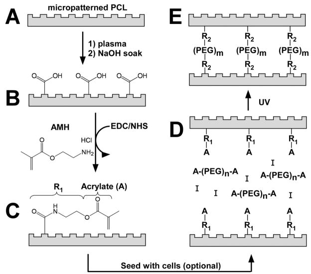
A surface modification technique previously used on PLGA, PGA, and PLLA scaffolding ([12]; [13]) was adapted to immobilize aminoethyl methacrylate hydrochloride (AMH, Sigma-Aldrich, Milwaukee, Wisconsin) onto the PCL scaffold, thus leaving an exposed acrylate group on the PCL surface (Figure 1). PCL scaffolds were first made hydrophilic by plasma oxidation (Plasma Cleaner/Sterilizer, Harrick, DCC-32G). Scaffolds were then soaked in ethanol for 5 min to remove debris. They were then rinsed with a 1 M NaOH solution and shaken for 5 min to hydrolyze surface ester bonds, exposing carboxylate groups on the surface of the film. The scaffolds were then rinsed in DI water until the pH of the rinsing solution was neutral. Scaffolds were then briefly rinsed in 0.1 M MES (2-(N-Morpholino) ethanesulfonic acid hydrate, Sigma-Aldrich, St. Louis, MO) buffer. Treatment with EDC (1-ethyl-3-(3-dimethylaminopropyl) carbodiimide hydrochloride, Sigma-Aldrich, St. Louis, MO) (50mM in 0.1M MES buffer) and NHS (N-hydroxysulfosuccinimide sodium salt, Sigma-Aldrich, St. Louis, MO) (50 mM in 0.1 M MES buffer) was then carried out to activate the carboxyl groups rendering them reactive to the primary amine on AMH. Scaffolds were soaked in the EDC/NHS solution for 30 min under constant agitation. Following activation of the carboxyl groups, scaffolds were briefly rinsed in 0.1 M MES buffer then soaked in an AMH solution (50 mM in 0.1 M MES buffer) for 1 hr with constant agitation Scaffolds were then rinsed in 0.1 M MES to remove unbonded AMH. An acrylate-containing photopolymerizable hydrogel can then be securely bonded to the AMH-modified PCL.
Figure 1. PCL modification schematic depicting the covalent bonding of AMH to the PCL surface and 3-D cellularized layered construct fabrication process.
Micropatterned PCL (A) was first hydrolyzed with NaOH. Exposed carboxyl groups (B) are then activated using EDC/NHS, and AMH was then bonded to the PCL surface via an amide bond (C). Note: The functionalization occurs both on the top and bottom surfaces of the PCL film, but only the top side is illustrated in the schematic for simplicity. At this point, cells can be seeded onto the patterned side of the substrates. Photopolymerizable polyethylene glycol (PEG) gels, containing acrylate groups are then used to crosslink (D) the PCL layers together via acrylate interactions (E). While only two sheets are shown to be bonded here for the sake of simplicity, up to five sheets may stacked in step D and bonded with a single UV exposure.
X-ray photoelectron spectroscopy (XPS)
XPS spectra were acquired using a Kratos AXIS Ultra Imaging X-ray Photoelectron Spectrometer with a monochromatic Al-Kα-X-ray small spot source (1486.6 eV) and multichannel detector. A concentric hemispherical analyzer (CHA) was operated in the constant analyzer transmission mode to measure the binding energies of emitted photoelectrons. The binding energy scale was calibrated by the Au4f7/2 peak at 83.9 eV, and the linearity was verified by the Cu3p1/2 and Cu2p3/2 peaks at 76.5 and 932.5 eV respectively. Survey spectra were collected from 0 to 1100 eV with pass energy of 188 eV, and a high-resolution scan was taken for the C1s peak with pass energy of 23.5 eV. All spectra were referenced by setting the hydrocarbon C1s peak to 285.0 eV to compensate for residual charging effects. Data for percent atomic composition, atomic ratios and peak fit analysis parameters were calculated using the manufacturer supplied software.
Scanning Electron Microscopy (SEM)
To evaluate scaffold structure before and after surface treatments and layering, Scanning Electron Microscopy (SEM) (JSM-6100, Peabody, CA) was used to image scaffold surfaces and cross-sections. Scaffolds were coated with a 20 nm thick gold coating and images were taken at 5 kV. The layered scaffolds were not coated with gold and were imaged using a field emission scanning electron microscope (Zeiss Supra 40 FESEM).
Cell culture
Vascular smooth muscle cells (VSMC Coriell Cell Repositories (AG08504), Camden, NJ) from bovine aorta were seeded onto PCL scaffolds at a concentration of 15,000 cells/cm2 in Dulbecco’s Modified Eagles Medium (DMEM-low glucose (Gibco, Grand Island, NY)) supplemented with 10% penicillin/streptomycin (Gibco), L-glutamine (Gibco) and bovine calf serum (Hyclone, Logan, UT). Scaffolds were soaked in PBS overnight under UV to wet and sterilize them followed by a 30 min soak in media to allow for the deposition of serum proteins, after which VSMCs were seeded onto the scaffolds.
Determination of cell number
The Alamar Blue assay (Biosource, Camarillo, CA) was utilized to colorimetrically detect cell number on PCL scaffolds. The percentage of Alamar Blue reduced in culture media over time is an indication of the relative viability of the culture. Scaffolds were removed from original culture wells 48 hr after cell seeding and placed in fresh well plates in order to isolate only those cells attached to the scaffold. Media samples were taken 2 and 24 hr after the addition of Alamar Blue and assayed using a plate reader at 630 and 570 nm to determine the percentage of Alamar Blue reduced at each time point. A correction factor [14] was employed to take into account spectrophotometric detection at 630 nm instead of 600 nm. The percentage of Alamar Blue reduced over 22 hours was then calculated and converted to cell number via a calibration curve produced by measuring the percentage of Alamar Blue reduced for known numbers of cells (data not shown).
Cell orientation
To determine VSMC orientation, cells were fixed with cold acetone (−20 °C) for 20 min and the cell nuclei were stained with propidium iodide (PI, Molecular Probes, Carlsbad, CA; 10μL/mL in PBS, 10 min) [15], or fixed in 3.7% formaldehyde for 20 min and the cells were stained with 5-chloromethylfluorescein diacetate (CMFDA, Molecular Probes, Carlsbad, CA, 1 μl/mL for 20 min incubation followed by 30 min incubation in media). Images were obtained with a fluorescence microscope (Olympus BX60 equipped with an Olympus digital camera and connected to a computer with Image Pro Data acquisition software). Cell angle was determined by measuring the angle created by the long axis of the cell nucleus (PI staining) or cell cytoplasm (CMFDA staining) and the direction of the grooved pattern, where small angles indicate cells that are highly oriented to the pattern. The distribution of cell nuclei angles has been previously shown to be indicative of overall cell orientation [16].
VSMC viability and orientation on PCL scaffolds with crosslinked PEG-DA
Micropatterned AMH-modified or unmodified PCL scaffolds were seeded with VMSCs then coated with a photopolymerizable poly(ethylene glycol)-diacrylate (PEG-DA, MW 8000, SunBio, South Korea) (Figure 1). Cells grown on a glass cover slide served as a control. Briefly, cells were incubated for 48 hr, after which 70μL of PEG-DA solution (10% PEG-DA, 0.1% Irgacure 2959 (I2959), Ciba Specialty Chemicals, Newport, DE) was pipetted over the surface and crosslinked in a UV oven (UVItec Crosslinker CL-508, Cambridge, UK) at room temperature (0.7 J of 365 nm). The dosage and photoinitiator concentration values were chosen based our results of VSMC viability to UV exposure ranging from 0.25 – 0.8 J (at 365 nm) and I2959 concentrations ranging from 0.05 – 0.5% (data not shown). Moreover, 0.7J was the minimum exposure required for gel formation. Culture medium was then pipetted over the scaffolds and cells were allowed to culture for 24 or 48 hr, after which cell number was determined by monitoring the amount of Alamar Blue assay reduced over a 22 hr period. After 5 days of culture, cell orientation was investigated via propidium iodide nuclear staining as described above.
Unseeded 3-D construct stability under cell culture conditions
Unseeded AMH-modified or unmodified micropatterned PCL scaffolds were coated with a thin layer of 10% PEG-DA solution with Irgacure 2959 as in the manner described above. Three scaffolds were then stacked and subsequently exposed to UV light (365 nm, 0.7 J) in order to polymerize the PEG-DA gel and bond the individual PCL layers together as illustrated in Figure 1 (it should be noted that while this figure only shows the bonding of two substrates for the sake of clarity, up to five sheets may be stacked in step D and bonded using a single UV exposure). These three-layered constructs were then placed in a 6-well plate with culture media and agitated in a shaker bath (New Brunswick Scientific, Classic Series C78) at 85 rpm in a humidified 37 °C environment for 5 days. The integrity of the constructs was monitored daily. The construct was classified as ‘unstable’ when the layers separated from each other. Ten constructs of each condition were investigated.
Cell number and orientation on seeded 3-D constructs
VSMCs were seeded onto AMH-modified micropatterned PCL scaffolds and incubated for 48 hr. As described above, a thin layer of 10% PEG-DA solution with Irgacure 2959 was pipetted over the cell-seeded surfaces. Three scaffolds were stacked and subsequently exposed to UV light (365 nm, 0.7 J) in order to polymerize the PEG-DA gel and bond the individual PCL layers together (Figure 1). Cell culture media was added to the layered cellularized scaffolds and incubated for 24 or 48 hr.
Cell number and orientation were assessed as previously described. After 24 hr and 48 hr time points, layered scaffolds with seeded cells were peeled apart in order to determine cell number (Alamar Blue) and orientation (nuclear angle) of each individual layer, as described above for cells on non-layered PCL films.
Statistics
Data were analyzed using the SPSS for Windows (v.11.0.1) software package. One-way ANOVAs were used to test for differences in the means of measured quantities amongst groups of samples subjected to various levels of a parameter of interest. Levene’s test was used to test for homogeneity of population variances amongst groups. In all cases, no significant difference in variances was observed; therefore, post hoc comparisons were performed using the Tukey HSD procedure, which assumes equal variances between groups. A significance level of α = 0.05 was used for all tests.
Results
Fabrication of thin micropatterned PCL scaffolds
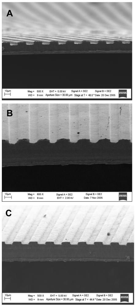
SEM images (Figure 2) of scaffolds placed on end demonstrates the thickness of PCL scaffolds as well as the molded groove patterning. Average scaffold thickness was 46 ± 13 μm, with a range of 31–64 μm. Moreover, SEM imaging showed no micropatterning loss with either NaOH- or AMH-modification.
Figure 2. SEM images of PCL scaffold cross-sections for untreated (500X), NaOH-treated (600X) and AMH-treated (600X) scaffolds.
Images demonstrate maintenance of grooved pattern integrity throughout surface chemical modification. (Scale bars: 10μm).
XPS analysis of AMH-modified PCL scaffold surface
Surface modification of PCL scaffolds with AMH was investigated using XPS. PCL surface chemistry was determined for pristine PCL, NaOH-treated PCL, AMH-adsorbed PCL and fully AMH-modified PCL. As a control, AMH-adsorbed PCL was not EDC- and NHS-treated. Nitrogen, present in AMH, was revealed through surface nitrogen scans. For fully EDC/NHS and AMH-treated scaffolds, the nitrogen mass concentration was 3.69% (Table 1). This level was higher level than detected on simply AMH-adsorbed scaffolds (nitrogen, 1.68%) indicating a higher incorporation of AMH on the surface of fully treated scaffolds.
Table 1. XPS results for the surfaces at the various steps of modification.
PCL surface chemistry was determined for pristine PCL, NaOH-treated PCL, AMH-adsorbed PCL and EDC/NHS & AMH-modified PCL. Scans for nitrogen, which is present in AMH, was shown to increase only after the EDC/NHS & AMH modification steps (A). Results for scans for carbon-oxygen bonds in the case of EDC/NHS & AMH modification were also consistent with the successful modification of PCL with AMH (B).
| A | ||||
|---|---|---|---|---|
| Survey Scan | Mass Concentration(%) | |||
| PCL | NaOH Treated | AMH Adsorbed | EDC/NHS & AMH Treated | |
| Nitrogen | -- | -- | 1.68 | 3.69 |
| B | ||||
| High Res O1s Scans | % Intensity | |||
| PCL | NaOH Treated | AMH Adsorbed | EDC/NHS & AMH Treated | |
| C=O | 53.5 | 51.7 | 56 | 78.8 |
| C--O | 46.5 | 48.3 | 44 | 21.2 |
Cell number on AMH-modified scaffolds
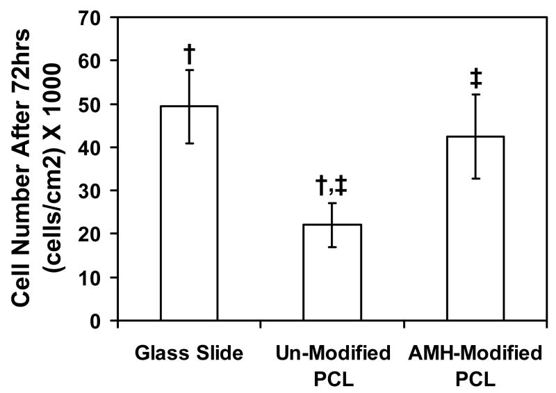
In order to determine whether the surface modification procedure affects cell number, VSMCs were seeded onto modified and unmodified PCL scaffolds as well as tissue culture plastic. Cell number was significantly lower on un-modified substrates as compared to AMH-modified substrates (p < 0.05) (Figure 3). In addition, cell number on modified PCL was similar to that on glass slides, a positive control, which indicates an acceptable level of biocompatibility of AMH-modified PCL, but not un-modified PCL, with VSMC culture. Negligible levels of percent reduced Alamar Blue were observed for both modified and unmodifed scaffolds in the absence of cells (data not shown), indicating that neither PCL nor AMH interferes with Alamar Blue readings.
Figure 3. VSMC cell number on AMH-modified and unmodified PCL scaffold after 72 hr of culture.
Cells grown on non-modified PCL scaffolds do not support cell growth at the same levels as the glass slide control substrate. AMH-modification allows the PCL substrates to support cell growth at the same level as the control substrates. Paired symbols (†, ‡) indicate a statistically significant difference (p < 0.05) between groups.
Cell orientation on AMH-modified scaffolds
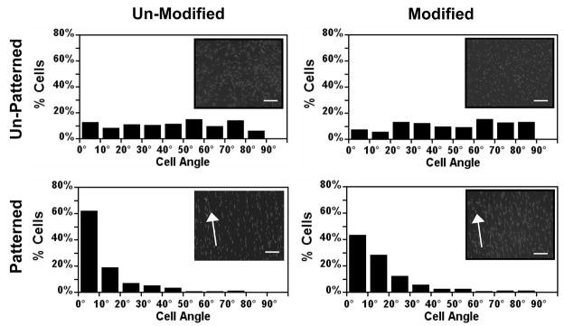
Cells grown on unpatterned substrates showed no preferred orientation angle with angles evenly distributed from 0° to 90° (Figure 4). In contrast, cells on patterned substrates strongly oriented in the direction of the micropattern with a majority of the cells having orientation angles less than 30° (88.4% and 84.5%, for un-modified and modified substrates, respectively), indicating that AMH-modification has no effect on cell orientation.
Figure 4. Effect of micropatterning on cell angle distribution on AMH-modified and unmodified scaffolds after 96 hr of culture.
Angles were widely distributed on unpatterned scaffolds. On patterned scaffolds cell angles cluster at low angles, indicating highly oriented cells. Inlay images: VSMCs were fixed and stained with nuclear stain propidium iodide. Cell nuclei can be seen oriented on both modified and unmodified patterned PCL while those on unpatterned PCL appear more randomly oriented. Images taken at 10x magnification.
Cell orientation and number on patterned PCL under a PEG-DA gel
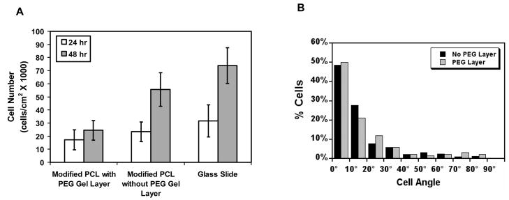
The effects of the presence of PEG-DA gel on VSMCs cultured on modified PCL were investigated in order to determine whether the layering of PEG-DA gel adversely affects cell number and orientation. After 24 hr, there was no significant difference between the number of cells on substrata with or without PEG-DA as well as the glass slide control. However, at 48 hr, cell number was lower on PCL scaffolds coated with PEG-DA gel compared to scaffolds without PEG-DA (p < 0.05) (Figure 5A). While this data indicates that the PEG gelation process does not result in significant cell death, it does demonstrate that cell proliferation is affected.
Figure 5. Effect of PEG-DA gel on cell number.
(A) Cell number of seeded VSMCs under a PEG-DA gel layer compared with cells seeded onto a substrate without a PEG-DA gel layer and a glass slide control, indicating that the PEG-DA layer inhibits proliferation, but does not result in cell death. (B) Nucleus angle distribution on AMH-modified PCL scaffolds with and without a PEG-DA gel layer, indicating the PEG-DA layer does not affect VSMC orientation.
In order to confirm that VSMCs seeded onto a micropatterned PCL scaffold maintain their orientation even in the presence of PEG-DA, VSMCs were seeded onto a modified PCL scaffold and allowed to culture for 5 days under a PEG-DA gel layer. Figure 5B shows that cells on both modified patterned PCL scaffolds and scaffolds with a PEG-DA layer were highly oriented in the direction of the micropattern with a majority of cells having orientation angles less than 30° (84.0% and 83.1%, respectively). No cells were seen at other focus levels within the PEG-DA gel, indicating cell migration into the PEG-DA gel was limited (data not shown). In contrast, when VSMCs were cultured under a layer of collagen gel, cells migrated into the gel and subsequently became randomly oriented (data not shown).
SEM imaging of layered scaffolds
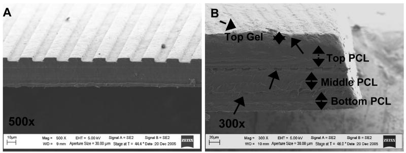
3-D constructs layered 3 PCL layers thick with intermediate PEG-DA gel layers were imaged using FESEM. From FESEM imaging, three distinct scaffold layers can be seen with patterning from each layer being visible (Figure 6). PEG-DA gel on the top PCL layer as well as between PCL layers can also be seen. PEG-DA gel thickness was difficult to determine from FESEM imaging since samples must be dehydrated to be mounted within the vacuum chamber. PEG-DA can be identified on the scaffold surface by flaky areas that were not present on scaffolds without PEG-DA (Figure 6A).
Figure 6. SEM images of multi-layered PCL-PEG-DA scaffolds with 3 PCL layers.
(A) Single PCL scaffold approximately 40 μm thick (without PEG-DA layer), patterned with grooves 5μm deep, 48μm wide, spaced 12μm apart. (Scale bar: 10 μm.) (B) Layered PCL-PEG-DA scaffold with 3 layers. Three distinct scaffold layers and topographical pattern on each scaffold layer is shown. A layer of PEG-DA gel can also be seen on the top scaffold layer. (Scale bar: 20 μm).
Stability of modified PCL scaffolds under cell culture conditions
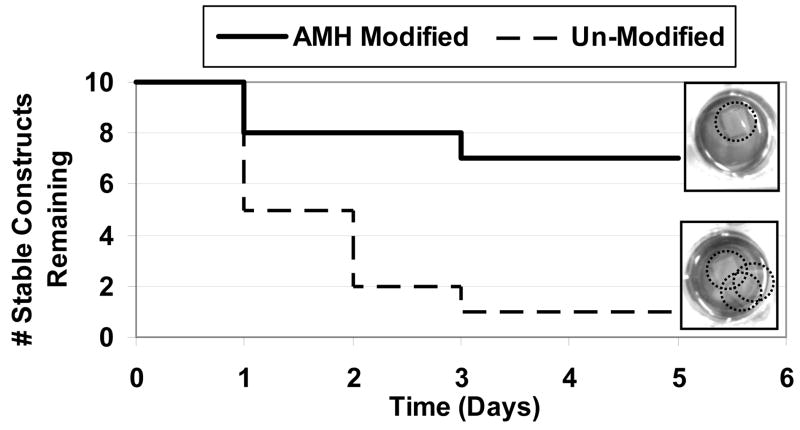
Construct stability for modified scaffolds was compared to that of unmodified scaffolds (Figure 7). Within one day of shaking, 50% of the unmodified constructs fell apart whereas 80% of the modified scaffolds remained stable. After 5 days, 70% of AMH-modified scaffolds (compared to only 10% of unmodified scaffolds) remained adhered under cell culture conditions.
Figure 7. Comparison of stability of AMH-modified and unmodified scaffolds in the layered configuration.
Layered 3-D construct stability when exposed to a heated and humidified environment with fluid flow for 5 d. n = 10 for both substrate conditions. 70% of AMH-modified scaffolds remain stable while only 10% of unmodified scaffolds remain adhered. Insets: Digital images of unmodified and modified 3-layer PCL scaffolds. Each well contains one multilayered construct. Top: AMH-modified scaffolds remain adherent over 5 days of exposure to cell culture conditions. Bottom: Unmodified scaffolds become unstable after 3 days of exposure to cell culture conditions. Several individual scaffolds can be seen in each well instead of one layered construct.
Cell distribution and orientation in the 3-D layered configuration
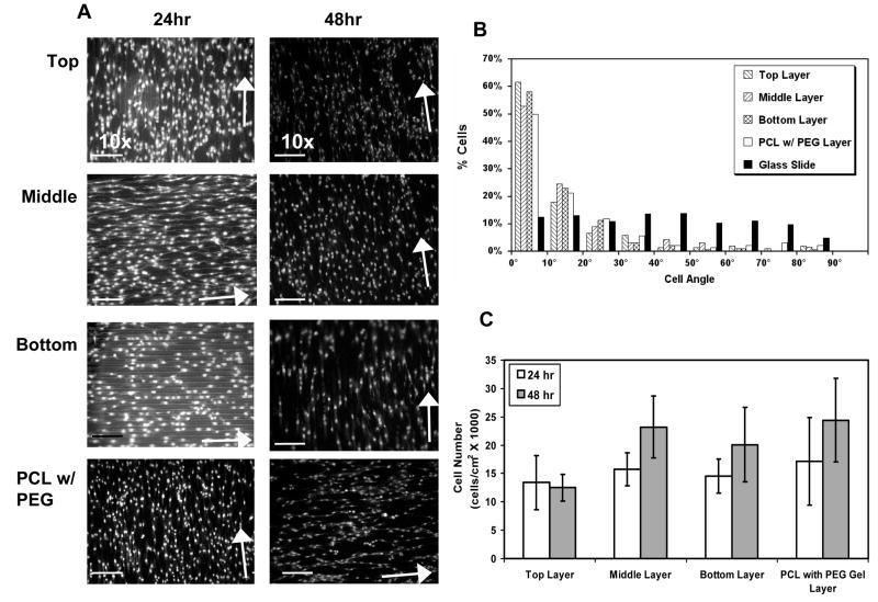
At 24 and 48 hr after layering cellularized 2-D scaffolds into a 3-D configuration, scaffolds were separated and stained with PI nucleus stain in order to investigate cell coverage and orientation. Uniform coverage of VSMCs was seen over the entire scaffold area in all scaffold layers (Figure 8A). Media accessible to cells within the PEG-DA gel as well as media diffusion through the PEG-DA gel layers may have contributed to sustained cell viability within the center of the construct up to 48 hr after layering.
Figure 8. VSMC number and orientation in scaffold with layered configuration.
(A) Propidium iodide staining of VSMCs seeded onto micropatterned PCL and layered with intermediate PEG-DA gel for 24 and 48h. Scaffolds were separated and fixed before staining. Arrows indicate the direction of the micropattern. (B) Nucleus angle distribution on scaffolds layered for 24 and 48h then separated. Cells in each patterned layer were strongly oriented in the direction of the micropattern as demonstrated by the biased distribution of the cell angles toward the direction micropattern. In contrast, cells on the the non-patterned glass slides (black bars) showed a uniform distribution of cell angles. The cell orientation for the layered scaffolds was similar to that observed for cells that were grown under a PEG-DA gel layer but not stacked. (C) Cell number in the stacked layers after 24h and 48h. With the exception of the cell number in the top layer after 48 hr, there were no differences observed between the various layers. See text for discussion of the top layer at the 48 hr time point.
Cell orientation on layered scaffolds was also maintained 24 and 48 hr after layering with a majority of the cells having orientation angles below 30° (86.2%, 86.6%, and 92.5% for the top, middle, and bottom layers, respectively) (Figure 8B). In addition, cells on the top, middle and bottom scaffold layers had similar orientation distributions to those on PCL with a PEG-DA gel layer on top.
Cell number in the 3-D layered configuration
VSMC number on micropatterned PCL scaffolds and subsequently layered into 3-D constructs was quantified at each level of the construct (top, middle and bottom) 24 and 48 hr after being layered. These cell numbers were compared to values obtained for cells seeded on PCL with a PEG-DA gel layer cross-linked over the culture (Figure 8C). The numbers of cells in the top, middle and bottom layers of the construct were not significantly different from the cell number found on a single PCL layer covered with a PEG-DA gel layer at 24 hr. At 48 hr, middle and bottom PCL layers maintained similar cell number values as a single layer PCL scaffold modified with PEG-DA. However, at 48 hr, the top layer had significantly fewer cells than any of the other layers.
Discussion
In this study, we have demonstrated the feasibility of fabricating a multi-layered tissue construct with micropatterned cells by transferring microfabrication technology from simple 2-D scaffolds to complex 3-D architectures. Specifically, we have developed a method to fabricate 3-D tissue constructs that incorporate controlled cellular organization by layering cellularized 2-D micropatterned biodegradable scaffolds. The fabricated 3-D layered micropatterned tissue constructs were composed of three major components: micropatterned AMH-modified PCL scaffolding, VSMCs and PEG-DA hydrogel. Micropatterned PCL scaffolding was fabricated such that it was thin, modified with an acrylate group, and patterned with topographical cues. These characteristics were critical for maintaining a stable layered construct that maintains organized cell orientation. Thickness was a critical parameter because of limited UV penetration: we found that a PCL scaffold thickness of approximately 40 μm is adequate for UV penetration to build stable 3-layered constructs (up to 5 days).
Covalent modification of the PCL scaffolds with an acrylate group was necessary for adhesion of acrylate-containing photopolymerizable hydrogels to the scaffold surface. It is important to note that the PEG-DA layers were critical not only for promoting adhesion between the PCL layers but also for maintaining VSMC orientation. Initially, we used type I collagen as an adhesive layer, but when VSMCs were cultured under a layer of collagen gel, cells migrated into the gel and subsequently became randomly oriented. This is not surprising, as PEG-DA is well-known to be protein-resistant, whereas type I collagen is bioactive. Our results agree with studies by Glass-Brudzinski et al. [17] that report an overall random reorientation of previously oriented cells in the presence of collagen gel that is not recoverable over time. Specifically, they cultured fibroblasts on micropatterned titanium of varying pattern depth with a layer of collagen gel above the culture and noted that cells in contact with the pattern oriented in the direction of the pattern, while those that moved into the collagen gel became randomly oriented.
It is also important to note that our method described here can be translated to other polymer systems. We chose PCL because it has a convenient Tg that made it relatively easy to process (compared to PLGA, e.g.) in our custom-made melt-molding device. As long as the polymer surface can be modified with acrylate groups, it is possible to covalently attach PEG-DA as an adhesive layer between scaffolds. However, the optimization of photoinitiator concentration, UV exposure level, and time must be optimized for each material and cell type. We note that the UV exposure does affect cell proliferation. This is in agreement with studies reported in the literature for the same photoinitiator (Irgacure 2959) and a photopolymerizable gel [18]. However, it is difficult to directly compare our studies quantitatively with this particular study because there are differences in photoinitiator concentration and composition (not to mention cell type), and the wattage and wavelength are not reported. We also note that the top layer has a lower cell number at 48 hours, which we attribute to the observed partial drying of the top gel layer as a result of the increased handling time for the stacked constructs compared with a non-stacked PCL substrate with a PEG layer.
An attractive feature of PCL that we did not exploit in this study is the ability to tune its degradation properties through co-polymerization with monomers with more rapidly degrading groups [19]. Moreover, PLGA/PCL/PLGA tri-block copolymers have been shown to have enhanced elasticity compared to PCL polymers: PLGA/PCL/PLGA with controllable degradability over a 2-month period have been reported with Young’s moduli in the range of 20 MPa [20]. Finally, PEG-DA gel can also be made biodegradable, laying the framework for a fully biodegradable system [21]. In the future it will be important to transfer this 3-D fabrication technique into a scaffold with faster degradation properties as well as a degradable PEG-DA gel in order to determine whether cell orientation is maintained as scaffold degradation occurs
A major difference between our approach and those of other groups that have developed layered 3-D porous micropatterned scaffolds is that their assembly processes utilize solvents and other non-cell friendly techniques, necessitating cell seeding after scaffold construction [7, 8]. Cell seeding in pre-formed scaffolds is limited by porosity and therefore limits the scale of micropatterning. Consequently, less area for cell attachment is available under these conditions. It is difficult to directly compare our results to that of other groups because to date, these scaffolds have only been created as proof-of-concept, and very little cell work has been demonstrated.
In this study, we have demonstrated that we can build 3-D constructs with precise control of cell organization over multiple length scales. Our cell viability results in these 3-D constructs are promising, but further investigation into the long-term maintenance of cell viability, orientation, and scaffold stability are needed before the feasibility of this approach can be fully assessed. It is important to note that the polymer scaffolding is intended only as a provisional template for tissue growth and therefore polymer degradation and cell-based remodeling, both in static and dynamic (bioreactor) culture, will need to be fully investigated. Nevertheless, our data show that this approach is a promising means of engineering tissues with defined structural organization for a wide variety of applications. Moreover, the ability to investigate VSMC response in 3-D may reveal important tools for the design of functional tissue replacements.
Acknowledgments
We are grateful to NASA (JYW, TD), NIH (JYW), AHA (JBL), and Johnson and Johnson (TD) for financial support. We thank Dr. Phil Allen in the BME Whitaker BioImaging Facility for assistance with the confocal studies and Dr. Ketul Popat for XPS analysis.
References
- 1.Fung Y-C. Biomechanics: Mechanical Properties of Living Tissues. New York: Spinger-Verlag; 1993. p. 433. [Google Scholar]
- 2.Desai TA. Med Eng Phys. 2000;22:595. doi: 10.1016/s1350-4533(00)00087-4. [DOI] [PubMed] [Google Scholar]
- 3.Bhatia SN, Yarmush ML, Toner M. J Biomed Mater Res. 1997;34:189. doi: 10.1002/(sici)1097-4636(199702)34:2<189::aid-jbm8>3.0.co;2-m. [DOI] [PubMed] [Google Scholar]
- 4.Flemming RG, Murphy CJ, Abrams GA, Goodman SL, Nealey PF. Biomaterials. 1999;20:573. doi: 10.1016/s0142-9612(98)00209-9. [DOI] [PubMed] [Google Scholar]
- 5.Thakar RG, Ho F, Huang NF, Liepmann D, Li S. Biochem Biophys Res Commun. 2003;307:883. doi: 10.1016/s0006-291x(03)01285-3. [DOI] [PubMed] [Google Scholar]
- 6.Sarkar S, Dadhania M, Rourke P, Desai TA, Wong JY. Acta Biomaterialia. 2005;1:93. doi: 10.1016/j.actbio.2004.08.003. [DOI] [PubMed] [Google Scholar]
- 7.Tsang VL, Bhatia SN. Adv Drug Deliv Rev. 2004;56:1635. doi: 10.1016/j.addr.2004.05.001. [DOI] [PubMed] [Google Scholar]
- 8.Papenburg BJ, Vogelaar L, Bolhuis-Versteeg LA, Lammertink RG, Stamatialis D, Wessling M. Biomaterials. 2007;28:1998. doi: 10.1016/j.biomaterials.2006.12.023. [DOI] [PubMed] [Google Scholar]
- 9.Vozzi G, Flaim C, Ahluwalia A, Bhatia S. Biomaterials. 2003;24:2533. doi: 10.1016/s0142-9612(03)00052-8. [DOI] [PubMed] [Google Scholar]
- 10.Yang Y, Basu S, Tomasko DL, Lee LJ, Yang ST. Biomaterials. 2005;26:2585. doi: 10.1016/j.biomaterials.2004.07.046. [DOI] [PubMed] [Google Scholar]
- 11.Sarkar S, Lee G, Wong J, Desai T. Biomaterials. 2006 doi: 10.1016/j.biomaterials.2006.04.038. [DOI] [PubMed] [Google Scholar]
- 12.Lee KB, Yoon KR, Woo SI, Choi IS. J Pharm Sci. 2003;92:933. doi: 10.1002/jps.10556. [DOI] [PubMed] [Google Scholar]
- 13.Oh SH, Kang SG, Kim ES, Cho SH, Lee JH. Biomaterials. 2003;24:4011. doi: 10.1016/s0142-9612(03)00284-9. [DOI] [PubMed] [Google Scholar]
- 14.Serotec. Serotec Product Data Sheet: alamarBlue. Kidlingto; Oxford: [Google Scholar]
- 15.Norman JJ, Desai TA. Tissue Eng. 2005;11:378. doi: 10.1089/ten.2005.11.378. [DOI] [PubMed] [Google Scholar]
- 16.Dalby MJ, Riehle MO, Yarwood SJ, Wilkinson CD, Curtis AS. Exp Cell Res. 2003;284:274. doi: 10.1016/s0014-4827(02)00053-8. [DOI] [PubMed] [Google Scholar]
- 17.Glass-Brudzinski J, Perizzolo D, Brunette DM. J Biomed Mater Res. 2002;61:608. doi: 10.1002/jbm.10243. [DOI] [PubMed] [Google Scholar]
- 18.Hynes SR, McGregor LM, Rauch MF, Lavik EB. J Biomater Sci Polymer Edn. 2007;18:1017. doi: 10.1163/156856207781494368. [DOI] [PubMed] [Google Scholar]
- 19.Jeong SI, Kim BS, Kang SW, Kwon JH, Lee YM, Kim SH, Kim YH. Biomaterials. 2004;25:5939. doi: 10.1016/j.biomaterials.2004.01.057. [DOI] [PubMed] [Google Scholar]
- 20.Choi SH, Park TG. Journal of Biomaterials Science, Polymer Edition. 2002;13:1163. doi: 10.1163/156856202320813864. [DOI] [PubMed] [Google Scholar]
- 21.Gobin AS, West JL. Faseb J. 2002;16:751. doi: 10.1096/fj.01-0759fje. [DOI] [PubMed] [Google Scholar]


