

Abstract
Large-conductance, voltage- and Ca2+-gated potassium (BK) channels control excitability in a number of cell types. BK channels are composed of α subunits, which contain the voltage-sensor domains and the Ca2+- sensor domains and form the pore, and often one of four types of β subunits, which modulate the channel in a cell-specific manner. β4 is expressed in neurons throughout the brain. Deletion of β4 in mice causes temporal lobe epilepsy. Compared with channels composed of α alone, channels composed of α and β4 activate and deactivate more slowly. We inferred the locations of the two β4 transmembrane (TM) helices TM1 and TM2 relative to the seven α TM helices, S0–S6, from the extent of disulfide bond formation between cysteines substituted in the extracellular flanks of these TM helices. We found that β4 TM2 is close to α S0 and that β4 TM1 is close to both α S1 and S2. At least at their extracellular ends, TM1 and TM2 are not close to S3–S6. In six of eight of the most highly crosslinked cysteine pairs, four crosslinks from TM2 to S0 and one each from TM1 to S1 and S2 had small effects on the V50 and on the rates of activation and deactivation. That disulfide crosslinking caused only small functional perturbations is consistent with the proximity of the extracellular ends of TM2 to S0 and of TM1 to S1 and to S2, in both the open and closed states.
Introduction
The large-conductance, voltage- and Ca2+-activated K+ (BK) channels are regulators of cellular excitability in neurons and smooth muscle. K+ current through BK channels shifts the membrane potential in the hyperpolarizing direction, suppressing the activity of voltage-dependent Ca2+ channels and thereby decreasing cytoplasmic [Ca2+]. Both membrane potential and cytoplasmic Ca2+ determine the equilibrium between the closed and the open states (Cui and Aldrich, 2000; Zhang et al., 2001).
The BK α subunit contains a voltage-sensor domain. In addition, the cytoplasmic C-terminal two-thirds of α contains multiple Ca2+-binding sites, including two RCK domains, resembling those of the bacterial Ca2+-gated K+ channel MthK (Jiang et al., 2002). The K+ conducting pathway is formed by a tetramer of α subunits.
In many cell types, the BK complex contains, in addition, four β subunits. There are four types of β subunits, β1–β4, the products of the KCNMB1, KCNMB2, KCNMB3, and KCNMB4 genes. Their expression is cell specific (Orio et al., 2002). β4 is expressed exclusively in brain. β4, like β1, slows both activation and deactivation of BK channels. In β4 knock-out mice, abnormal BK channel gating kinetics lead to abnormal firing and temporal lobe seizures (Brenner et al., 2005). In the presence of Ca2+, β4, however, has considerably smaller effects than β1 on the conductance–voltage relationship (Behrens et al., 2000; Brenner et al., 2000; Meera et al., 2000; Wang et al., 2006). In addition, BK channels with β4 are particularly resistant to block by charybdotoxin and iberiotoxin (Behrens et al., 2000; Meera et al., 2000), likely attributable to the large, extracellular loop of β4 reaching to and occluding the toxin binding sites in the region of the pore.
The differences in the effects of β1 and β4 on channel function must reflect differences in their homologous structures and in their interfaces with α. We determined previously the proximities and locations of the extracellular ends of the two transmembrane (TM) helices, TM1 and TM2, of β1 relative to the seven TM helices, S0–S6, of α (Liu et al., 2008b). We now find that, as in β1, β4 TM1 is closest to α S1 and S2 and that β4 TM2 is closest to S0. There are differences in the crosslinking patterns of β4 that lead us to consider other arrangements of TM1, TM2 and S0 relative to S1–S6, consistent with the crosslinking data.
Materials and Methods
Constructs.
Mutants of the BK α subunit (mSlo1, KCNMA1; GenBank accession number NM_010610; 1169 residues; molecular weight 131,700) and human BK β4 subunit (KCNMB4, Open Biosystems clone/accession number 3873518, catalog #MHS1010-9204471; 210 residues; molecular weight 23,800) were generated by site-directed mutagenesis using the QuikChange XL (Stratagene) kit. Cys substitutions in α (Fig. 1A) were made in a pseudo-wild-type (pWT) background, in which Cys14 and Cys141 were each mutated to Ala. The C terminus of the β4 construct was tagged with a 3X FLAG epitope (DYKDHDGDYKDHDIDYKDDDDK). Cys substitutions in β4 (Fig. 1B) were made in a pWT background, in which Cys 38 and Cys 173 were each mutated to Ala.
Figure 1.

Mouse BK α and β4 subunits. A, Scheme of the threading of BK α through the membrane. The residues substituted by Cys in the extracellular regions flanking S0–S6 are labeled. B, Scheme of the threading of BK β4 through the membrane. The residues substituted by Cys in the extracellular regions flanking TM1 through TM2 are labeled.
Expression, surface biotinylation, and cell lysis.
HEK293 cells were cultured and transfected as described previously (Morrow et al., 2006). After 24–48 h, the cells were collected, washed, and biotinylated with 2 mm sulfosuccinimidyl-6-(biotinamido) hexanoate (sulfoNHS-LC-biotin) (Pierce), a membrane-impermeant reagent, in Dulbecco's PBS (DPBS). The cells were solubilized for 20 min at 4°C in lysis buffer (1% Triton X-100, 150 mm NaCl, 50 mm Tris, 1 mm EDTA, 2 mm N-ethylmaleimide, and Roche complete protease inhibitors). Insoluble material was removed by centrifugation.
Treatment with dithiothreitol and QPD.
HEK293 cells were kept on the tissue culture dish, washed, and biotinylated with 4 mm sulfoNHS-LC-biotin solution. The cells were then washed with DPBS, and a solution of 137 mm NaCl, 2.7 mm KCl, 0.1 mm CaCl2, 0.1 mm MgCl2, and 40 mm HEPES was added to the dish. Dithiothreitol (DTT) was added for a final concentration of 20 mm. These cells were then washed with DPBS, collected, and lysed as detailed above.
In most experiments, no oxidizing agent was added to the cells. In experiments to test the susceptibility of two Cys on the cell surface to reform a disulfide after reduction, as described previously (Liu et al., 2008a), we used the doubly charged oxidant, 4,4 ′-(azodicarbonyl)-bis-[1,1-dimethylpiperazinium, diiodide] [quaternary piperazinium diamide (QPD)] (Kosower et al., 1974). For cells treated with QPD, cells were resuspended in a solution of 137 mm NaCl, 2.7 mm KCl, 0.9 mm CaCl2, and 0.49 mm MgCl2. QPD was then added to a final concentration of 40 μm. Cells were then washed and lysed as detailed above.
Quantitating crosslinking.
The cell lysate was mixed with Neutravidin–Sepharose beads (Pierce) for 90 min at room temperature. In a typical sample, lysate of cells from a 60 mm plate in 300 μl of lysis buffer was mixed with 30 μl of a 50% slurry of Neutravidin beads, previously washed and suspended in lysis buffer. The beads were washed in a solution of 0.05% SDS, 40 mm HEPES, pH 7.4, and 1 mm EDTA. To elute bound protein, we added 80 μl of 6 m urea, 4% SDS, 200 mm Tris, pH 8, and 2 mm EDTA and heated the mixture to 100°C for 2 min. After a short spin, the supernatant was collected. The samples were then electrophoresed, transferred to nitrocellulose, and immunoblotted by sequential treatment with anti-BK-α-C-terminus antibody (BD Biosciences) or anti-FLAG antibody (Sigma-Aldrich), horseradish-peroxidase-conjugated secondary antibody, and ECL reagent (Pierce Super Signal West). We quantitated the chemiluminescence from each band with a CCD camera (Carestream Health) and ImageQuant software (Molecular Dynamics). We calculated the extent of crosslinking, from the band at 155 kDa divided by the sum of the bands at 125 and 155 kDa. All mutants were independently expressed and tested twice if there was little crosslinking and three or more times if there was substantial crosslinking. In each experiment, duplicate lanes were run. Finally, the averages of the individual means were calculated. Intrasubunit crosslinking of α, with or without the presence of β4, was determined as described previously (Liu et al., 2008a).
For comparing the crosslinking of different pairs of flanks, we calculated a weighted mean of the top three extents of crosslinking between these flanks. We weighted the individual Cys pairs in the two flanks by the sum of the number of residues that the two Cys were out from the membrane, for example, if one Cys was the second residue out from the membrane in the first flank and the other Cys was the third residue out from the membrane in the second flank, the extent of crosslinking was multiplied by . The weighted mean was the sum of the weighted extents of crosslinking divided by the sum of the weights.
Functional effects of crosslinking.
Conductance–voltage (G–V) curves and the activation and deactivation kinetics were determined as described previously (Zakharov et al., 2005; Morrow et al., 2006; Liu et al., 2008b). We determined the effects of mutation and crosslinking on V50 and on the rate constants of activation (kact) and deactivation (kdeact). The effect on V50 was calculated as ΔV50 = V50,MUT − V50,pWT. The effects on the rate constants of opening and closing were calculated as log(kMUT/kpWT). We calculated the effect attributable to substituting the disulfide-bonded cysteine (i.e., completely crosslinked Cys) and the effect attributable to substituting two reduced cysteines (i.e., completely reduced Cys) as described previously (Liu et al., 2008b).
Results
Mutant α and β4
We mutated to Cys, one at a time, at least the first four residues predicted to be just extracellular to the membrane-embedded residues of α S0–S6 and similarly of β4 TM1 and TM2 (Fig. 1A,B). The mutations were made in pWT α and β4 constructs (see Materials and Methods). We showed previously that the functional characteristics (V50 and rate constants for activation and deactivation) of pWT α are only slightly different from those of WT α (Liu et al., 2008a). We now have found that the functional properties of channels formed by pWT α and pWT β4 differ only slightly from those of wild-type α and β4 (data not shown). All 208 combinations of 26 Cys-substituted mutants of pWT α and eight Cys-substituted mutants of pWT β4 were coexpressed in HEK293 cells. The proteins on the cell surface of the intact cells were labeled with an impermeant biotinylation reagent. The detergent-solubilized, biotinylated cell-surface proteins were captured on Neutravidin beads and released in nonreducing SDS-PAGE sample buffer.
We found that almost all combinations of a Cys-substituted α and a Cys-substituted β4 were well expressed on the cell surface. Only combinations αA295C and αT297C expressed poorly and were not further analyzed.
Disulfide crosslinking of Cys-substituted α and β4 mutants
As described previously (Liu et al., 2008a,b), we determined the extent of disulfide bond formation in surface-expressed channels in the absence of any oxidizing agent other than ambient oxygen. This endogenous disulfide bond formation could be attributable to spontaneous oxidation by dissolved oxygen or to catalytic oxidation by protein disulfide isomerase (PDI) homologs in the endoplasmic reticulum (Wilkinson and Gilbert, 2004) or by secreted PDI homologs (Jiang et al., 1999) or secreted oxidases (Becker et al., 2006). Whatever the mechanism of disulfide bond formation, we assume that the extent of formation reflects the relative proximity of the two Cys before disulfide bond formation.
The mobility of pWT α by SDS-PAGE corresponds to an apparent molecular mass of ∼125 kDa (Fig. 2A). Coexpressed with pWT α, pWT β4 ran as three bands in the range of 25–35 kDa (supplemental Fig. 1, available at www.jneurosci.org as supplemental material). These bands correspond to an unglycosylated, a core glycosylated, and a maturely glycosylated β4 (Jin et al., 2002). The disulfide crosslinked dimer of Cys-substituted α and Cys-substituted β4 ran as one or two very close bands of apparent molecular mass ∼155 kDa (Fig. 2). Several examples of pairs of Cys-substituted α and β4 that gave this crosslinked complex are shown. The ∼155 kDa band was absent in extracts of cells expressing pWT α and pWT β4 (Fig. 2) or from cells coexpressing Cys mutants of α and pWT β4 or, conversely, of pWT α and Cys mutants of β4 (data not shown); no single mutant yielded the ∼155 kDa band. Furthermore, the ∼155 kDa band contained α crosslinked to β4: the band disappears after reduction of the sample with DTT, and the 125 kDa α band appears (Fig. 2A,B). In addition, the ∼155 kDa band, but not the 125 kDa band, bound an anti-FLAG antibody that recognized the FLAG-tagged β4 (supplemental Fig. 2, available at www.jneurosci.org as supplemental material).
Figure 2.

Detecting disulfide crosslinking between BK α and β4 subunits. A, Western blots illustrating endogenous crosslinking of Cys-substituted α and Cys-substituted β4. Expression of mutants, selection of channels transported to the cell surface, SDS gel electrophoresis, and blotting are described in Materials and Methods. The blots were developed with an antibody against an epitope from the C terminus of α, which recognizes α (125 kDa) and the crosslinked α–β4 complex (∼155 kDa). Half of each sample was reduced with DTT (+DTT lanes). Under each gel is the fraction of crosslinked α–β4 complex in the unreduced lane. B, Reduction and reoxidation of the disulfide between R17C and I168C, P137C and S41C, and F144C and L44C. Channels on intact cells were reduced with DTT and oxidized for 20 min with 40 μm QPD. At the bottom of each lane is the fraction of crosslinked α–β4 complex.
The disulfide bond between Cys-substituted α and β4 could be reduced in intact cells by DTT and reoxidized on the cell surface with the membrane-impermeant, quaternary ammonium diamide derivative QPD. This is shown for three pairs of Cys-substituted α and β4 that were initially almost completely endogenously crosslinked: one pair each from α S0–β4 TM2, α S1–β4 TM1, and α S2–β4 TM1 (Fig. 2B).
Quantitating α–β4 subunit crosslinks
Cys substituted in the TM1 flank formed disulfides most readily with Cys in the flanks of S1 and S2 (Fig. 3A), whereas Cys in the flank of TM2 formed disulfides most readily with Cys in the flank of S0 (Fig. 3B). Among the 16 combinations of a Cys in the TM1 flank and a Cys in the S1 flank, seven combinations formed disulfides to an extent >60% (Fig. 3A). The average of the top three extents of crosslinking was 77 ± 4%. Similarly, among the 16 combinations of a Cys in the TM1 flank and a Cys in the S2 flank, nine combinations formed disulfides to an extent >60% (Fig. 3A). The average of the top three extents of crosslinking was 78 ± 10%. In contrast, the TM1 flank crosslinked much less to the flanks of S0, S5, and S6 or the S3–S4 loop. The number of combinations of a Cys in these other flanks and a Cys in the TM1 flank that formed disulfides to an extent >20% was none for S0, three for S3–S4, one for S5, and one for S6. Only one of these combinations, TM1 A43C and S3–S4 N200C, reached 30% crosslinking. The averages of the top three extents for S3–S4, S5, and S6 were 27 ± 3, 14 ± 7, and 14 ± 13%, respectively. By either criterion, the extracellular flank of TM1 is closer to the flanks of S1 and S2 than to the flanks of S3–S4, S5, and S6.
Figure 3.
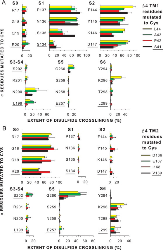
Extents of endogenous disulfide bond formation between Cys substituted in the extracellular flanks of α and β4. A, α S0–S6 flanks and β4 TM1 flank. B, α S0–S6 flanks and β4 TM2 flank. The α residues substituted by Cys are indicated along the left edge of each vertical axis, and the β4 residues substituted by Cys are color coded as shown. The extent of disulfide bond formation is represented by bars in the horizontal direction. In the cases in which the mean extent of disulfide bond formation was zero, the value 0.5% was plotted to identify these pairs as tested. The residues closest to the membrane are underlined.
Disulfide crosslinking from TM2 was even more restricted than from TM1. Among the 16 combinations of a Cys in the TM2 flank and a Cys in the S0 flank, 11 combinations formed disulfides to an extent >60% (Fig. 3B). The average of the top three extents was 81 ± 5%. There was little disulfide formation with the flanks of S1 and S2 or the S3–S4 loop: the averages of the top three extents were 4 ± 1, 10 ± 3, and 7 ± 1%, respectively. There was 40–50% crosslinking from two TM2 flanking positions to one position in the S5 flank and no crosslinking to the other three S5 flanking positions. The average of the top three extents of crosslinking was 38 ± 16%. One Cys in the TM2 flank, V169C, crosslinked just <30% to S6 flank K296C. The average of the top three extents was 21 ± 7%. The flank of TM2 is close to the flank of S0, has some access to the flanks of S5 and S6, and has little access to the flanks of S1 and S2 and the S3–S4 loop.
We have represented the salient features of the crosslinking as lines linking the extracellular ends the TM helices of α and β4 drawn as circles (Fig. 4). The circles labeled S1–S6 were superimposed on the extracellular ends of these helices in two structures of Kv1.2. The structure underlying model 1 is a Rosetta model of the closed state (Yarov-Yarovoy et al., 2006), and the structure underlying models 2 and 3 is the x-ray crystallographic solution of the presumed open state of the potassium channel Kv1.2 (Long et al., 2005). In models 1 and 2, the extracellular end of S0 is in a cove between S2 and S3, in which we placed it previously (Liu et al., 2008a). In model 3, the extracellular end of S0 is placed outside of the voltage-sensor domain helices S1–S4, close to the short loop between S3 and S4. In each of the models, TM1 is placed close to S1 and S2, and TM2 is placed close to S0, as is consistent with the crosslinking results. It is important to note that the crosslinking of S0 to S1 and to S3–S4 was not different in the presence of β4 (supplemental Fig. 3, available at www.jneurosci.org as supplemental material) than it was in the presence of β1 or in the absence of either β (Liu et al., 2008a).
Figure 4.

Locations of the extracellular ends of β4 TM1 and TM2 relative to the extracellular ends of α S0–S6. Model 1, A Rosetta model of Kv1.2 in the closed state (Yarov-Yarovoy et al., 2006) is the template for locating the extracellular ends of BK α S1–S6, represented as number circles. The position of S0 is as reported previously (Liu et al., 2008a). Models 2 and 3, The template is the crystal structure of Kv1.2 in the open state (Long et al., 2005). In Model 2, the position of S0 relative to S1–S4 is the same as in model 1. In model 3, the position of S0 is outside of S1–S4. The locations of the extracellular ends of β4 TM1 and TM2 are represented by labeled black and white circles. TM1 and TM2 from two β4 subunits are represented by white circles with black numbers and two β4 subunits by black circles with white letters. In models 1 and 2, TM1 and TM2 from one β4 subunit straddle one α subunit. In model 3, TM1 and TM2 from one β4 subunit are between two α subunits. For each pair of flanks, the mean of the top three extents of crosslinking (see Materials and Methods) is coded by the thickness of the connecting line (see legend in figure). To indicate the distance of a crosslink from the ends of the TM helices, we added the number of residues out from the membrane of each of the two Cys. The mean of these distances for the top three extents of crosslinking is indicated by the color of the line (see legend in figure). P, Pore.
The mean of the top three extents of crosslinking for each pair of flanks were calculated as above, except that the extents were weighted by the inverse of the sum of the number of residues the Cys were away from the membrane, giving greater weight to crosslinks that were close to the membrane than to those that were farther away. These means were binned, and the three bins were represented by lines of different thicknesses (Fig. 4). In addition, to represent the distance of the crosslinks from the membrane, the lines were color coded in bins of the mean sum of the number of residues the Cys were away from the membrane. As we showed previously, close to the membrane, the extracellular end of S0 is next to the short loop between S3 and S4 (Liu et al., 2008a). The β4 helix TM1 is closest to S1 and S2, and TM2 is closest to S0, although these crosslinks are on average farther from the membrane than the crosslinks between S0 and S3–S4.
Functional effects of the crosslinks
Three functional parameters were determined: V50 for activation and the rate constants for activation and deactivation (Fig. 5). The effect on V50 was taken as V50 for the channel composed of Cys-substituted α and Cys-substituted β4 minus V50 for the channel composed of pWT α and pWT β4. The effect on rate constants was taken as the log of the quotient of the rate constant for the mutant channel divided by the rate constant for pWT channel. For each channel, we characterized its function both before reduction with DTT, when α and β4 were predominantly disulfide crosslinked, and after reduction with DTT, when they were predominantly reduced. Using the densities of the α band and the α–β4 band in the immunoblots from the cells before and after reduction with DTT, under the same conditions used in the functional studies (supplemental Table 1, available at www.jneurosci.org as supplemental material), we estimated the fraction of disulfide-crosslinked dimer and of reduced monomer under the two conditions. We assumed that the extent of each functional effect was the linear sum of the effect of the disulfide times the extent of crosslinking plus the effect of the two reduced Cys times the extent of reduction. From two equations, one for the oxidized state and one for the reduced state, in two unknowns, we calculated the functional effect attributable to the two Cys substitutions (i.e., completely reduced state) and the functional effect attributable to the disulfide (i.e., completely oxidized state) (Liu et al., 2008b). The functional parameters of the channel composed of pWT α and pWT β4 was unaffected by DTT (Fig. 5B).
Figure 5.
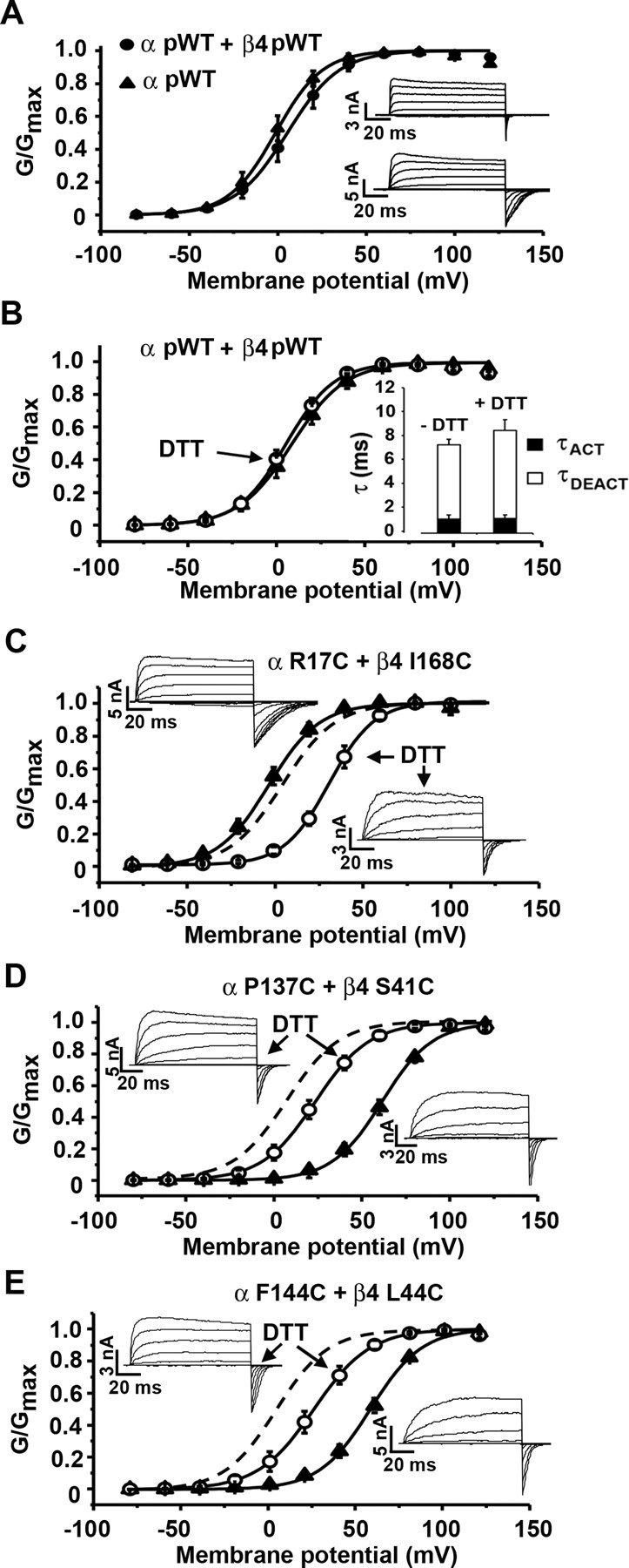
Activation, deactivation, and conductance–voltage curves for pWT and mutant channels. A, Normalized conductance as a function of voltage (G–V curve) for pWT α (filled triangles) and pWT α and pWT β4 (filled circles). The recordings were made in outside-out macropatches with 10 μm Ca2+ inside the pipette. Inset, Macroscopic currents conducted by pWT α (top) and pWT α and pWT β4 (bottom) in response to step depolarizations from −80 to +140 mV. B, G–V curve for pWT α + pWT β4 before (filled triangle) and after 20 mm DTT (open circle). Inset, Graph showing τACT and τDEACT in absence and presence of DTT. C–E, Macroscopic currents and G–V curves were determined with 10 μm Ca2+ inside the pipette before (filled triangles) and after (open circles) DTT for α R17C and β4 I168C (C), α P137C and β4 S41C (D), and α F144C and β4 L44C (E). Dashed lines represent the G–V curve for pWT α and pWT β4. Error bars are SD.
We determined the functional properties of eight combinations of Cys-substituted α and Cys-substituted β4. Four involved S0 and TM2, two involved S1 and TM1, and two involved S2 and TM1. All eight double-Cys mutant channels formed disulfides to an extent 65% or greater. All were functional in both the fully reduced and fully oxidized forms: they were activated by depolarization and deactivated by hyperpolarization. Therefore, none of the residues mutated to Cys was irreplaceable for function.
In six of the eight pairs of mutants tested, the disulfide changed V50 <16 mV in either the positive or negative direction (Fig. 6A). The six included the four pairs involving the S0 flank and the TM2 flank, S1 N136C and TM1 A43C, and S2 D147C and TM1 L44C. In all of these cases, the effect of substituting the two reduced Cys was equal or greater than the effect of the disulfide-crosslinked Cys (Fig. 5C), although none of the effects were large. Disulfide crosslinking of these six pairs also perturbed the activation rate constant only slightly, within 0.4–2.1 times (Fig. 6B). In contrast, crosslinking of the pair S1 P137C and TM1 S41C (Fig. 5D) and the pair S2 F144C and TM1 L44C (Fig. 5E) increased V50 by ∼60 mV, and, also in these two cases, kact decreased 7- to 8-fold and increased kdeact 1.5- to 2.1-fold. Considering the effect of crosslinking one flank to another, the average changes in V50 attributable to crosslinking TM1 to S1 and TM1 to S2 were greater than that attributable to crosslinking TM2 to S0 (supplemental Fig. 4, available at www.jneurosci.org as supplemental material).
Figure 6.
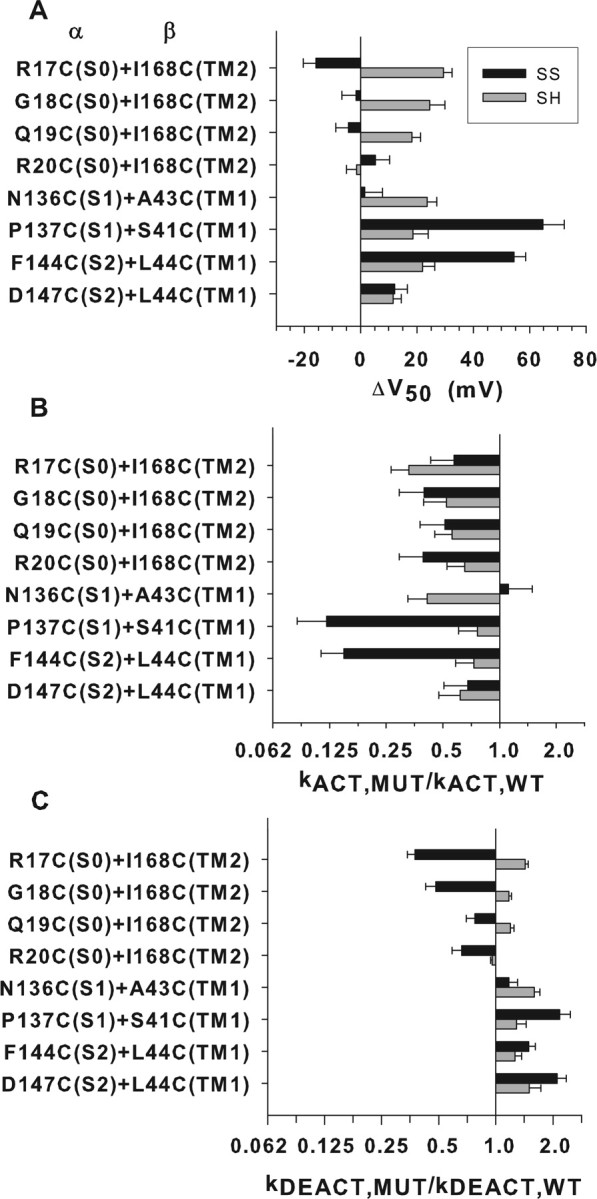
Functional effects of the substitution of native residues by cysteines and their endogenous disulfide crosslinking. Eight pairs of Cys-substituted α and Cys-substituted β4 were expressed in HEK 293 cells. Recordings were in outside-out macropatches with 10 μm Ca2+ in the pipette. Black bars show the effects attributable to the disulfide, and gray bars show the effects attributable to the substitution of the two Cys for native residues. Effects on V50 (A), the rate constant for opening (B), and the rate constant for closing (C) were extrapolated to 100% crosslinking or 100% reduction as described previously (Liu et al., 2008b). SS, Disulfide-bonded Cys; SH, reduced Cys.
Discussion
Proximity inferred from disulfide crosslinking
We inferred from the extent of disulfide bond formation between Cys in α and Cys in β4 that the extracellular end of TM1 is close to the extracellular ends of S1 and S2 and that the extracellular end of TM2 is close to the extracellular end of S0 (Fig. 4). The disulfide crosslinking that we measured was restricted to channels transported to the cell surface. Because the cell selects against transporting misfolded or misassembled proteins (Nikles and Tampé, 2007; Nakatsukasa and Brodsky, 2008), the structures of these channels are likely to be at least near native. Also, the greater the extent of crosslinking of two Cys, the closer on average they were before crosslinking (Liu et al., 2008a). We tried to average the effects of factors other than proximity by testing multiple pairs of Cys in each pair of flanks.
Model of BK α and β4
Taking three-dimensional structures of Kv1.2 as templates, we tested which arrangements of S0 and of TM1 and TM2 were consistent with the crosslinking. Previously, we (Liu et al., 2008a) picked the Rosetta-generated model for Kv1.2 in the closed state (Yarov-Yarovoy et al., 2006) as the template, because it is likely that the crosslinking we observed occurred in the closed state of the BK channel. It is possible, however, that in the closed state of the BK channel, the voltage-sensing domains are close to their position in the open state (Ma et al., 2006). Furthermore, even in the closed state of Kv1.2, the extracellular end of S1 is close to the pore helix, as it appears in the in Kv1.2 crystal structure (Lee et al., 2009). This leads us to consider also the high-resolution structure of the open state of Kv1.2 (Long et al., 2005) as a template. The important difference between the structures of the closed state and the open state for our purposes is the counterclockwise rotation of the voltage sensor in the modeled closed state relative to the solved open state.
We (Liu et al., 2008a) previously located the extracellular end of S0 between S2 and S3 in the closed state model (Fig. 4, model 1). We now also consider the open state with S0 placed between S2 and S3 (model 2) and the open state with S0 placed outside of S3–S4 (model 3). In models 1 and 2, the observed crosslinking of the extracellular flank of S0 to the flanks of S1, S2, and S3–S4 is readily rationalized. This location of S0 in model 1 is also consistent with the absence of crosslinking of S0 to S5 and S6. In model 3, however, in which S3–S4 is rotated away from S5 and S6, S0 can also be placed outside the S1–S4 bundle, close to S3–S4 without S0 being close to S5 or S6.
Model 3 has the advantage that S0 does not disrupt the S1–S4 bundle; however, S0 is farther from S1 and S2 in model 3 than in models 1 and 2. There was extensive crosslinking from the flank of S0 to the flanks of S1 and S2, but this was predominantly between Cys three or four residues out from the membrane on both flanks. This distance out from the membrane in both S0 and in S1 or S2 might accommodate the flank of S0 reaching over the loop between S3 and S4 to the flanks of S1 and S2. In the native BK α structure, there is a disulfide bond between Cys14, seven residues out from the membrane domain of S0, and Cys141, eight residues out from both S1 and S2, in the middle of the loop between them, indicating that this is the direction taken by the S0 flank in the native structure.
In all three models, the positions of β4 TM1 and TM2 are consistent with the high extents of crosslinking of TM2 to S0 and of TM1 to S1 and S2. The low extents and the absence of crosslinking are also informative. The 25–30% crosslinking of TM1 to the S3–S4 loop and the absence of TM1 crosslinking to S0 favor model 3 because, if the TM1 flank can crosslink to the S3–S4 loop, it must pass S0 in models 1 and 2 but not in model 3. Furthermore, the ∼40–50% crosslinking of TM2 to S5, albeit between three and four residues out from the membrane on the TM2 flank and four residues out from the membrane on the S5 flank, and the absence of TM2 crosslinking to S3–S4 favor model 3. A notable difference between the models is that, in models 1 and 2, a β subunit associates with a single α voltage-sensor domain, whereas in model 3, a single β associates with the voltage-sensor domains of two α subunits.
The loop between β4 TM1 and TM2 reaches the vicinity of the central pore, in which it blocks binding of charybdotoxin and iberiotoxin (Behrens et al., 2000; Meera et al., 2000), so that the flanks of TM1 and TM2, the beginning and end of the loop, are headed in the direction of the extracellular flanks of S5 and S6. In all three models, the loop, containing 130 residues, could form a structure that reaches that far. In model 1, for example, the distances from the centers of the disks representing TM1 and TM2 are both ∼40 Å from the center of the pore, which could be spanned by the 130 residues in the β4 loop. As an example, siamensis toxin 3 contains 71 residues and five disulfide bonds and forms a flat structure that spans ∼20 × ∼40 Å (Betzel et al., 1991).
Comparison with β1
The patterns of crosslinking of β1 (Liu et al., 2008b) and of β4 (Fig. 3) were somewhat different (supplemental Fig. 4, available at www.jneurosci.org as supplemental material). TM2 of β1 was even more extensively crosslinked to S0 than was TM2 of β4, and furthermore there was more crosslinking close to the membrane in β1 than in β4. In β1, unlike in β4, TM2 crosslinked to S2 to an average extent of 36% (mean of top three extents). This result looks more likely in models 1 and 2 than in model 3. The absence of crosslinking of β4 TM2 to S2 could be a result of the distance in model 3 or the close association of TM1 with S2, blocking access to TM2. Also, in β1, the mean extent of crosslinking of TM1 to S0 was 42%, whereas in β4, there was no crosslinking of TM1 to S0. Conversely, β1 TM1 did not crosslink to S3–S4, whereas β4 TM1 did crosslink to S3–S4 to an average extent of 27%. In model 3, for example, this difference could be attributable to the closer association of β4 TM1 than β1 TM1 with S1 and S2 and, consequently, the shorter distance of TM1 to S3–S4. Although we show that β4 TM2 can crosslink weakly to S5, consistent with model 3, the aligned pair of Cys was not tested in β1. The subtle differences between β1 and β4 crosslinking to α may reflect differences in the positions of TM1 and TM2 relative to S0–S6 or differences in the structures and flexibilities of the two βs, in which the extracellular loops have different numbers of residues and of disulfides.
Functional effects of crosslinks
Eight of the most highly crosslinked pairs of Cys-substituted α and β4 were tested for the functional effects of the double mutation to Cys and for the effects of crosslinking these Cys. In six of these eight double-mutant channels, neither the substitution of cysteines, per se, nor their disulfide crosslinking had more than a modest effect on function. It seems unlikely that the contacts between the flanking regions themselves are crucial for the modulation of α by β4. It is quite likely that the underlying membrane-embedded helices, at least at their extracellular ends, are also in contact. Whether these contacts are essential in the modulation we do not yet know.
If there were extensive relative movement of these helices during activation, deactivation, or gating, crosslinking the extracellular flanks should affect one or more of these processes. If the relative movement were modest, it could be absorbed by the flexibility of the crosslinked flanks.
All four crosslinks S0 to β4 TM2 crosslinks tested decreased the rate constants for both opening and closing but at most threefold (Fig. 6). For each crosslinked pair, the effects on opening and closing were of similar magnitude, consistent with the modest effect of each of the crosslinks on V50 for opening. The crosslinks favored neither the open nor the closed state but somewhat retarded the transitions between them.
One of two crosslinks between S1 and β4 TM1 and one of two between S2 and TM1 slowed opening eightfold and accelerated closing twofold. In these cases, the V50 was shifted ∼60 mV to the right. These crosslinks strongly favored the closed state. In the other two pairs, however, there was little effect of crosslinking. Thus, it is unlikely that TM1 either translates or rotates relative to S1 and S2 during opening or closing; rather, the marked effects of the first two crosslinks were likely attributable to a propagated perturbation of the structure.
Crosslinking of β4 to α has, in general, less of an effect on V50 than does crosslinking of β1 to α (supplemental Fig. 4, available at www.jneurosci.org as supplemental material), perhaps because there is less of an effect of β4 on V50 in the first place. Both β1 and β4 slow opening and closing of the channel. In both cases, TM2 is interacting with S0, which closely interacts with S3–S4, the movement of which is central to voltage-sensing and activation and deactivation. It is possible that, in both β1 and β4, this indirect interaction with S3–S4 retards both activation and deactivation of the voltage sensors. What subtle differences in the interactions of β1 and β4 lead the first to strongly favor the open state in the presence of Ca2+ and the second not to do so is a question for future study.
Footnotes
This work was supported in part by National Institutes of Health (NIH) Research Grant Awards P01 HL081172 and R01 HL68093 from National Heart, Lung, and Blood Institute (NHLBI), R01 NS054946 from National Institute of Neurological Disorders and Stroke, and the Arlene and Arnold Goldstein Family Foundation. S.O.M. is an Established Investigator of the American Heart Association. R.S.W. is supported by a Glorney-Raisbeck Fellowship from the New York Academy of Medicine and T32 HL07854 from NIH–NHLBI. D.D. was supported by American Heart Association Founders Affiliate Medical Student Fellowship, and N.C. was supported by the Doris Duke Clinical Research Fellowship Program.
References
- Becker L, Nesheim ME, Koschinsky ML. Catalysis of covalent Lp(a) assembly: evidence for an extracellular enzyme activity that enhances disulfide bond formation. Biochemistry. 2006;45:9919–9928. doi: 10.1021/bi060283t. [DOI] [PubMed] [Google Scholar]
- Behrens R, Nolting A, Reimann F, Schwarz M, Waldschütz R, Pongs O. hKCNMB3 and hKCNMB4, cloning and characterization of two members of the large-conductance calcium-activated potassium channel beta subunit family. FEBS Lett. 2000;474:99–106. doi: 10.1016/s0014-5793(00)01584-2. [DOI] [PubMed] [Google Scholar]
- Betzel C, Lange G, Pal GP, Wilson KS, Maelicke A, Saenger W. The refined crystal structure of alpha-cobratoxin from Naja naja siamensis at 2.4-A resolution. J Biol Chem. 1991;266:21530–21536. doi: 10.2210/pdb2ctx/pdb. [DOI] [PubMed] [Google Scholar]
- Brenner R, Jegla TJ, Wickenden A, Liu Y, Aldrich RW. Cloning and functional characterization of novel large conductance calcium-activated potassium channel beta subunits, hKCNMB3 and hKCNMB4. J Biol Chem. 2000;275:6453–6461. doi: 10.1074/jbc.275.9.6453. [DOI] [PubMed] [Google Scholar]
- Brenner R, Chen QH, Vilaythong A, Toney GM, Noebels JL, Aldrich RW. BK channel beta4 subunit reduces dentate gyrus excitability and protects against temporal lobe seizures. Nat Neurosci. 2005;8:1752–1759. doi: 10.1038/nn1573. [DOI] [PubMed] [Google Scholar]
- Cui J, Aldrich RW. Allosteric linkage between voltage and Ca2+-dependent activation of BK-type mslo1 K+ channels. Biochemistry. 2000;39:15612–15619. doi: 10.1021/bi001509+. [DOI] [PubMed] [Google Scholar]
- Jiang XM, Fitzgerald M, Grant CM, Hogg PJ. Redox control of exofacial protein thiols/disulfides by protein disulfide isomerase. J Biol Chem. 1999;274:2416–2423. doi: 10.1074/jbc.274.4.2416. [DOI] [PubMed] [Google Scholar]
- Jiang Y, Lee A, Chen J, Cadene M, Chait BT, MacKinnon R. Crystal structure and mechanism of a calcium-gated potassium channel. Nature. 2002;417:515–522. doi: 10.1038/417515a. [DOI] [PubMed] [Google Scholar]
- Jin P, Weiger TM, Levitan IB. Reciprocal modulation between the alpha and beta 4 subunits of hSlo calcium-dependent potassium channels. J Biol Chem. 2002;277:43724–43729. doi: 10.1074/jbc.M205795200. [DOI] [PubMed] [Google Scholar]
- Kosower EM, Kosower NS, Kenety-Londner H, Levy L. Glutathione. IX. New thiol-oxidizing agents: DIP, DIP+1, DIP+2. Biochem Biophys Res Commun. 1974;59:347–351. doi: 10.1016/s0006-291x(74)80213-5. [DOI] [PubMed] [Google Scholar]
- Lee SY, Banerjee A, MacKinnon R. Two separate interfaces between the voltage sensor and pore are required for the function of voltage-dependent K+ channels. PLoS Biol. 2009;7:e47. doi: 10.1371/journal.pbio.1000047. [DOI] [PMC free article] [PubMed] [Google Scholar]
- Liu G, Zakharov SI, Yang L, Deng SX, Landry DW, Karlin A, Marx SO. Position and role of the BK channel alpha subunit S0 helix inferred from disulfide crosslinking. J Gen Physiol. 2008a;131:537–548. doi: 10.1085/jgp.200809968. [DOI] [PMC free article] [PubMed] [Google Scholar]
- Liu G, Zakharov SI, Yang L, Wu RS, Deng SX, Landry DW, Karlin A, Marx SO. Locations of the beta1 transmembrane helices in the BK potassium channel. Proc Natl Acad Sci U S A. 2008b;105:10727–10732. doi: 10.1073/pnas.0805212105. [DOI] [PMC free article] [PubMed] [Google Scholar]
- Long SB, Campbell EB, Mackinnon R. Voltage sensor of Kv1.2: structural basis of electromechanical coupling. Science. 2005;309:903–908. doi: 10.1126/science.1116270. [DOI] [PubMed] [Google Scholar]
- Ma Z, Lou XJ, Horrigan FT. Role of charged residues in the S1–S4 voltage sensor of BK channels. J Gen Physiol. 2006;127:309–328. doi: 10.1085/jgp.200509421. [DOI] [PMC free article] [PubMed] [Google Scholar]
- Meera P, Wallner M, Toro L. A neuronal beta subunit (KCNMB4) makes the large conductance, voltage- and Ca2+-activated K+ channel resistant to charybdotoxin and iberiotoxin. Proc Natl Acad Sci U S A. 2000;97:5562–5567. doi: 10.1073/pnas.100118597. [DOI] [PMC free article] [PubMed] [Google Scholar]
- Morrow JP, Zakharov SI, Liu G, Yang L, Sok AJ, Marx SO. Defining the BK channel domains required for beta1-subunit modulation. Proc Natl Acad Sci U S A. 2006;103:5096–5101. doi: 10.1073/pnas.0600907103. [DOI] [PMC free article] [PubMed] [Google Scholar]
- Nakatsukasa K, Brodsky JL. The recognition and retrotranslocation of misfolded proteins from the endoplasmic reticulum. Traffic. 2008;9:861–870. doi: 10.1111/j.1600-0854.2008.00729.x. [DOI] [PMC free article] [PubMed] [Google Scholar]
- Nikles D, Tampé R. Targeted degradation of ABC transporters in health and disease. J Bioenerg Biomembr. 2007;39:489–497. doi: 10.1007/s10863-007-9120-z. [DOI] [PubMed] [Google Scholar]
- Orio P, Rojas P, Ferreira G, Latorre R. New disguises for an old channel: MaxiK channel beta-subunits. News Physiol Sci. 2002;17:156–161. doi: 10.1152/nips.01387.2002. [DOI] [PubMed] [Google Scholar]
- Wang B, Rothberg BS, Brenner R. Mechanism of beta4 subunit modulation of BK channels. J Gen Physiol. 2006;127:449–465. doi: 10.1085/jgp.200509436. [DOI] [PMC free article] [PubMed] [Google Scholar]
- Wilkinson B, Gilbert HF. Protein disulfide isomerase. Biochim Biophys Acta. 2004;1699:35–44. doi: 10.1016/j.bbapap.2004.02.017. [DOI] [PubMed] [Google Scholar]
- Yarov-Yarovoy V, Baker D, Catterall WA. Voltage sensor conformations in the open and closed states in ROSETTA structural models of K+ channels. Proc Natl Acad Sci U S A. 2006;103:7292–7297. doi: 10.1073/pnas.0602350103. [DOI] [PMC free article] [PubMed] [Google Scholar]
- Zakharov SI, Morrow JP, Liu G, Yang L, Marx SO. Activation of the BK (SLO1) potassium channel by mallotoxin. J Biol Chem. 2005;280:30882–30887. doi: 10.1074/jbc.M505302200. [DOI] [PubMed] [Google Scholar]
- Zhang X, Solaro CR, Lingle CJ. Allosteric regulation of BK channel gating by Ca2+ and Mg2+ through a nonselective, low affinity divalent cation site. J Gen Physiol. 2001;118:607–636. doi: 10.1085/jgp.118.5.607. [DOI] [PMC free article] [PubMed] [Google Scholar]