Abstract
Purpose: In this study, the authors investigated the feasibility of a dual resolution volume-of-interest (VOI) cone beam breast CT technique and compared two implementation approaches in terms of dose saving and scatter reduction.
Methods: With this technique, a lead VOI mask with an opening is inserted between the x-ray source and the breast to deliver x-ray exposure to the VOI while blocking x rays outside the VOI. A CCD detector is used to collect the high resolution projection data of the VOI. Low resolution cone beam CT (CBCT) images of the entire breast, acquired with a flat panel (FP) detector, were used to calculate the projection data outside the VOI with the ray-tracing reprojection method. The Feldkamp–Davis–Kress filtered backprojection algorithm was used to reconstruct the dual resolution 3D images. Breast phantoms with 180 μm and smaller microcalcifications (MCs) were imaged with both FP and FP-CCD dual resolution CBCT systems, respectively. Two approaches of implementing the dual resolution technique, breast-centered approach and VOI-centered approach, were investigated and evaluated for dose saving and scatter reduction with Monte Carlo simulation using a GEANT4 package.
Results: The results showed that the breast-centered approach saved more breast absorbed dose than did VOI-centered approach with similar scatter reduction. The MCs in fatty breast phantom, which were invisible with FP CBCT scan, became visible with the FP-CCD dual resolution CBCT scan.
Conclusions: These results indicate potential improvement of the image quality inside the VOI with reduced breast dose both inside and outside the VOI.
Keywords: dual resolution cone beam CT, volume-of-interest, VOI mask, dose saving, scatter reduction, breast imaging, FDK reconstruction
INTRODUCTION
Breast cancer screening and diagnosis rely on the detection and visualization of calcifications and soft tissue masses in mammography. Microcalcifications (MCs), tiny calcium deposit within the breast, are routinely searched for as early indicators of breast cancer. The sizes of MCs vary, ranging from several millimeters to less than 100 μm. They can be presented as either an individual or a cluster. When five or more MCs are detected in a volume of 1 cm3 they are defined as a cluster of MCs.1 The size, shape, and number of MCs in a cluster are examined for cancer detection and diagnosis. Thus, improving the detection and visualization of the MCs is very important in breast cancer screening and diagnosis. Currently, mammography is the primary method used for breast cancer screening. However, a major limitation of mammography is overlapping of breast tissue structures with soft tissue masses or MCs in the two-dimensional (2D) mammograms. This compromises its use in the detection, diagnosis, and staging of breast cancer.2 It was reported that up to 15% of breast cancer are not identified with mammography and approximately 70%–90% of mammograms deemed to be suspicious of cancers are eventually found to be negative.3, 4
Breast tomosynthesis, which takes multiple x-ray images of the breast from many angles, can provide 3D images of the breast via reconstruction.5, 6 The resolution in the horizontal plane (perpendicular to x-ray tube to detector direction) is comparable to that of mammography; however, the resolution in the vertical plane (along x-ray tube to detector direction) is low due to the limited angle. Applying CT to detect breast cancer is not a new concept, it was introduced more than 2 decades ago.7 However, little progress was made due to the limitation of image quality and the exposure of the x-ray radiation dose. Although computed tomographic mammography (CTM) was studied in the late 1970s,8, 9, 10 this modality was has been largely dismissed due to concerns about radiation dose and cost effectiveness. We and other investigators have been studying the feasibility of using a pendant geometry cone beam CT (CBCT) scanner for breast cancer imaging.11, 12, 13 With the development of pendant geometry cone beam breast CT, only the breast itself is exposed to the x rays, preventing unnecessary radiation exposure to other parts of the body and providing largely isotropic spatial resolution 3D images. The visibility of MCs in cone beam breast CT with a flat panel (FP) detector has been investigated and reported.12, 14, 15, 16 It was reported that the visibility of large MCs (⩾250 μm) increased with increasing mean glandular dose, while the small MCs (<250 μm) were invisible probably due to the limited sensitivity of the FP detector and spatial resolution of the imaging system.14 Suryanarayanan et al.17 reported that high resolution detector with low imaging system noise could enhance the detection of MCs in mammography. Therefore, it is desirable to use high resolution and high sensitive detector and small size x-ray focal spot to improve the spatial resolution for detection of small MCs.
In diagnostic workup or staging, it may not be necessary to achieve the same high image quality throughout the entire breast. The radiologist or surgeons may be interested in a small volume with high image quality. In this situation, it is desirable to achieve high quality images of the volume of interest (VOI) without exposing the entire breast to high radiation doses. To solve this problem, we previously proposed a VOI CBCT technique.18 With this technique, it is possible to selectively image a VOI with high image quality, reduced scatter effect, and lowered radiation dose both inside and outside the VOI. However, the detectability of the small MCs inside the VOI would still be limited by the spatial resolution of the FP detector. The potential for utilizing charge-coupled device (CCD)-based detectors for small-field digital mammography has been previously investigated.19, 20, 21 It was found that the CCD detector could provide a spatial resolution closer to that of screen film mammography. Therefore, the CCD detector may help improve the detection and visualization of small MCs in CBCT.
Several approaches have been proposed for reconstruction of truncated fan beam or cone beam images;22, 23, 24, 25, 26, 27 however, these methods could not provide general solutions to all truncation patterns. In the works of Cho et al.22 and Zou et al.,24 their method works quite well for the truncation data close to peripheral region of interest (ROI) but is subject to artifacts for data truncation in all projection views. Clackdoyle et al.25 and Pack et al.26 suggested that iterative methods could possibly reconstruct larger ROI, but there was no evidence showing that their methods can deal with small ROI and different truncation situations.
As discussed in the previous paper,18 image reconstruction for the VOI still requires the use of projection data outside the VOI. To pad the truncated space outside the VOI, low resolution and low dose CBCT data maybe reprojected to provide projection data with same pixel size as high resolution CCD detector. We investigated the feasibility of using the high resolution and high exposure VOI projection data in conjunction with limited height, full width projection data acquired at low resolution, and low exposure to reconstruct high resolution CBCT images for the VOI. Patel et al.28 used similar approach to implement their ROI cone beam CT technique for neuroangiography.
There are two potential approaches to implement the dual resolution CBCT technique. One is to center the breast with the rotating axis and to move the VOI mask to track the VOI. The other is to center the VOI with the rotating axis, thus the position of the VOI mask is fixed during the scan. These two approaches were investigated and evaluated in terms of dose saving and scatter reduction at the detector with Monte Carlo simulation using GEANT4 package.
In this study, we investigated the feasibility of a dual resolution VOI CBCT technique and compared two implementation approaches in terms of dose saving and scatter reduction.
MATERIALS AND METHODS
Dual resolution cone beam CT technique
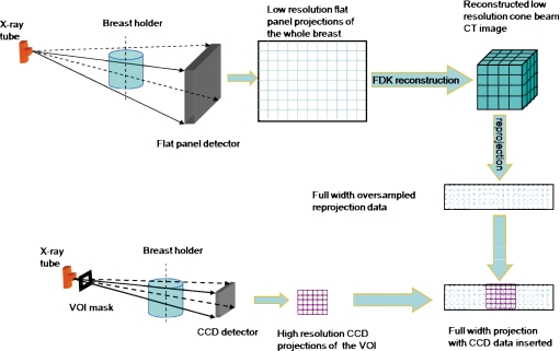
A schematic drawing for dual resolution CBCT technique was shown in Fig. 1. With this technique, full field projection images, acquired with a FP detector, are used to obtain CBCT images of the entire breast. If a suspicious region (VOI) in the breast is identified, a VOI mask with an opening is inserted and positioned between the x-ray source and the breast to deliver x-ray exposure to the VOI while collimating the x rays outside the VOI. A high resolution detector, such as CCD detector, is used to acquire the projection data of the VOI only. To fill the truncated space outside the VOI for reconstruction, full width pseudohigh resolution projection data are generated by reprojecting the low resolution CBCT image to match the new imaging geometric magnification (such as the new position of the breast and different x-ray source to detector distance), possible different numbers of projection views, and smaller pixel size of the high resolution detector. The dual resolution full width projection data, consisting of true high resolution data inside the VOI and pseudohigh resolution data outside the VOI, are then used to reconstruct the high resolution images for the VOI. The widely used Feldkamp–Davis–Kress (FDK) algorithm is used for image reconstruction.29
Figure 1.
Schematic diagram for dual resolution CBCT technique.
Benchtop system
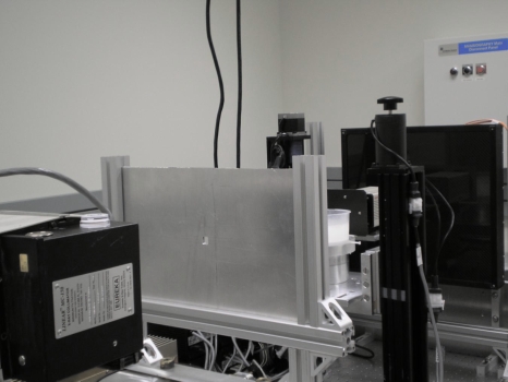
We have constructed and used a benchtop experimental CBCT system to demonstrate the dual resolution CBCT technique. As shown in Fig. 2, the system consisted of a radiographic x-ray tube (G-1593BI, Varian Medical Systems, Salt Lake City, UT) with 0.3 mm nominal focal spot size, a FP detector (FPD14, Anrad Corporation, Saint-Laurent, Canada), a high resolution CCD camera-based detector (C4742-56-12ER, Hamamatsu Corporation, Hamamatsu City, Japan), and a step motor driven rotating table to hold and rotate the object. The low resolution FP detector was a 1 mm thick amorphous selenium (a-Se)-based direct conversion digital detector with a pixel size of 150 μm and a bit depth of 12. The detector was designed for radiographic∕fluoroscopic imaging, featuring a detector size of 33.6×34.2 cm2, sufficient to cover the entire breast. The active area of the detector was divided into a 2304×2304 array of image elements. The high resolution detector was a digital CCD camera-based detector with an active area of 3.2×2.4 cm2. The CCD used has an intrinsic pixel size of 6.45 μm. A fiber optic taper was used to couple the CCDs to a scintillator (GdO2S:Tb), which converts incident x rays into light photons. The light photons were directed to the CCD detector via a fiber optic taper with a magnification ratio of 3.7:1, resulted in an effective pixel size of 24 μm. Finally, the CCD converts the light photons into 12 bit digital data, which were transmitted to and processed by a computer. The CCD detector was operated in a 2×2 pixel binning mode to provide a detector matrix size of 672×512 pixels with an effective pixel size of 48 μm. The x-ray source to rotational axis distance (SCD) was 88 cm. The x-ray source to CCD detector and Anrad FP detector distances (SIDs) were 102 and 135 cm, respectively. A lead mask with a rectangular opening was made for delivering x-ray exposure to the VOI while blocking unnecessary x-ray photons outside the VOI. The mask with 1.5 cm opening was then placed 66 cm away from the x-ray source. The center of the VOI mask opening was aligned with the rotating axis to generate a 2.0 cm diameter cylindrical VOI at the rotating center. The CCD detector and VOI mask were mounted on a translational stage to simultaneously move in and out of the field of view for high and low resolution image acquisition, respectively. The system configuration is shown in Table 1. All experiments were performed at 80 kVp with continuous x-ray exposure. The HVL of the 80 kVp x-ray spectra is 3.08 mm AL.
Figure 2.
Photograph of the experimental setup for FP-CCD based dual resolution CBCT.
Table 1.
Parameters of FP-CCD-based dual resolution CBCT system.
| Parameters | Low resolution detector | High resolution detector |
|---|---|---|
| Manufacturer | Anrad Corporation, Saint-Laurent, Canada | Hamamatsu Corporation, Hamamatsu city, Japan |
| Model | FPD14 digital detector | C4742-56-12ER digital CCD camera detector |
| X-ray absorber | a-Se | GdO2 S:Tb |
| Active area | 33.6×34.2 cm2 | 3.2×2.4 cm2 |
| Intrinsic pixel size | 150 μm | 6.45 μm |
| Effective pixel size | 150 μm | 24∕48 μm |
| Matrix size | 2304×2304 | 1344×1024∕672×512 |
| SCD | 88 cm | 88 cm |
| SDD | 135 cm | 102 cm |
| Magnification | 1.53 | 1.16 |
| Voxel size | 98 μm | 41 μm |
Breast phantom
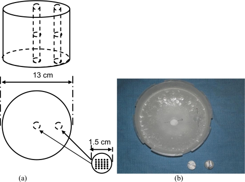
A 13 cm diameter paraffin cylinder was used to simulate the breast.30 Paraffin, which emulates fat in x-ray attenuation, was used for its ease of use in fabricating the phantom. Two 1.5 cm diameter holes were drilled at the center (inside the VOI) and near the edge (outside the VOI) to hold the paraffin rods containing simulated microcalcifications. The center-to-center distance between the holes was 4.5 cm. Five groups of calcium carbonate grains (Computerized Imaging Reference Systems, Norfolk, VA), ranging in size from 160–180 to 200–212 μm, were used to simulate MCs. Each MC group was arranged to form a 5×5 cluster and embedded into a 1.5 cm diameter paraffin rod, which was inserted into the holes in the breast phantom for imaging. The layout and photograph of the breast phantom were illustrated in Fig. 3. The CBCT images of the 5×5 cluster calcifications inside the 1.5 cm diameter paraffin rods were shown in Fig. 4.
Figure 3.
(a) Geometric configuration of a wax cylinder with two wax rods inserted at the center and close to the edge. (b) Picture of the breast phantom.
Figure 4.
Sequential slices images of a 1.5 cm diameter paraffin rod embedded with 5×5 160–180 μm calcifications. The CBCT images were obtained with CCD camera-based CBCT system.
Full width projection data outside the VOI
The reprojection algorithm used was developed by our group for modeling the imaged object with CT data for image simulation.31 It computes the line integrals of the object attenuation along the x-ray path with pixel-driven approach.32, 33 The process consisted of positioning the x-ray source and detector around the object, passing cone beam x rays through the object, and collecting the attenuated x-ray projection data at the detector.
The algorithm for computing the reprojection of a 3D volume may be summarized as follows:
-
(1)
Build an imaging system with x-ray source, 3D object, and detector.
-
(2)Convert CT number of the 3D object to corresponding linear attenuation coefficient with the equation,
where CTnumber, μtissue, and μwater represent the voxel value of the CT image, the linear attenuation coefficients of the breast phantom and water, respectively. In this study, μwater=0.2328 cm−1. -
(3)
Set geometry parameters such as SCD, SID, and rotating center.
-
(4)
Vary and set the position for the focal spot or the rotating angle.
-
(5)
Determine the x-ray path from the x-ray point source to the center of a detector pixel cell.
-
(6)
Determine the x-ray entry and exit points for the object.
-
(7)Compute the line integral from the entry point to the exit point, with the equation,
where (i,j,k) represents the voxel that the x-ray passed; I0 represents the intensity of the x-ray emitted from the x-ray source. The line integral was carried out with step size of 29.4 μm. -
(8)
Repeat procedures (5)–(7) for all the rays (specified by the row and column numbers of the detector pixels) in a projection geometry.
-
(9)
Repeat procedures (4)–(8) for all the projection views for a 360° scan.
Construction of dual resolution image
To demonstrate the dual resolution CBCT scanning technique, the breast phantom with two MC rods inserted at the center (inside the VOI) and near the edge (outside the VOI) of the cylinder was imaged with the Anrad FP detector. The 3D low resolution CBCT images of the entire breast phantom were first reconstructed with the FDK algorithm. The VOI mask and CCD detector were then moved into the field of view to collect the high resolution projection images of the VOI. Ray-tracing reprojection method was used to compute the projection data of the breast phantom with geometry parameters the same as those of CCD-based CBCT scan. The projection data were sampled with the same pitch as those of the CCD detector. Prior to the reprojection process, the reconstructed breast phantom image was carefully aligned to the same orientation as that of the VOI scan by shifting the rotating angle. The projection data inside the VOI were replaced with the measured high resolution CCD projection data angle by angle. The measured high resolution data of the VOI, combined with the reprojection pseudohigh resolution data outside the VOI, can be used to reconstruct the dual resolution CBCT images with the FDK algorithm. Note that the I0 in step 7 of the reprojection procedure should be carefully selected to match the intensity inside the VOI.
Monte Carlo calculation
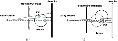
Two approaches can be used to implement VOI scanning for dual resolution CBCT. One is to center the breast on the rotating axis and then move the VOI mask to track the VOI [Fig. 5a]. The other is to align the VOI with the rotating axis so that the position of the VOI mask can be kept fixed during the scan [Fig. 5b]. We performed Monte Carlo simulation using the GEANT4 (geometry and tracking) package34 to evaluate and compare the breast-centered and VOI-centered approaches in terms of dose saving and scatter reduction. GEANT4 is a set of C++ libraries that provide the functionality necessary to perform Monte Carlo simulations of photons or other particles traveling through matter. In our simulation, the breast was modeled as a 13 cm diameter, 10 cm high cylinder of 100% fatty breast with a 2.0 cm diameter spherical VOI 5.0 cm away from the breast center in the radial direction. The compositions of the glandular and adipose tissues were defined as described by Hammerstein et al..35 Twelve 0.5 cm diameter, 0.5 cm high (equal to the size of TLD) cylinders, with 0.51 cm interval, were defined along the radial direction to accumulate the radiation energy deposited in their volumes. The physics processes considered included the photoelectric effect, Compton scattering, and Rayleigh scattering.
Figure 5.
(a) Top view of the breast-centered and (b) VOI-centered VOI scanning techniques.
In our simulation, the x-ray source and detector were assumed to be stationary, while the breast phantom rotated around the rotating axis. This is equivalent to the x-ray source and detector rotating around the breast in terms of dose and scatter estimation. To simulate the breast-centered approach, the central axis of the breast phantom was aligned with the rotating axis of the CBCT system. A 5 mm thick lead VOI mask with an opening was assumed to be located between the x-ray source and the breast phantom. To simulate the CBCT scan, the breast phantom was rotated for various projection views and the position of the VOI mask was recalculated to track the VOI for each view. To simulate the VOI-centered approach, the center of the VOI was assumed to be on the imaging axis and aligned with the rotating axis. The VOI mask was assumed to be stationary with its opening centered around the imaging axis. The breast phantom was assumed to rotate around the VOI center during the scan. 36 projection views were calculated with 10° interval. 107 55 keV (effective voltage of 80 kVp) x rays were tracked to simulate CBCT for each projection view.
The energy deposited by any photon interaction that took place in the breast phantom was accumulated and recorded as dose absorbed. The detector was modeled as a 1.0 mm thick selenium-based x-ray absorber divided into 5×5 mm2 pixels. The input energy of x rays at the detector was tallied separately for primary and scattered x rays and integrated as the primary and scatter image signals.
RESULTS
Experimental demonstration with calcification phantom
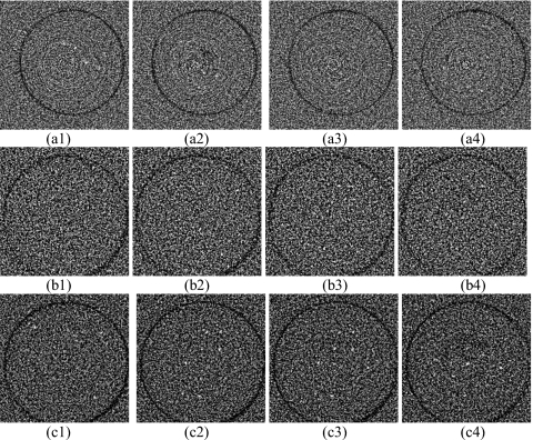
Figure 6 shows the FP and dual resolution CBCT images of the VOI (MC rod) at the center of the breast phantom (inside the VOI). The FP images were obtained with 0.9 mA s∕frame and 300 projection views (corresponding radiation dose of full field cone beam CT was 1.26 rad at the center of the breast). The MCs were invisible in FP CBCT images, as shown in Fig. 6a[(1)–(4)]. They became visible in the dual resolution CBCT images. Dual resolution CBCT images in Fig. 6b[(1)–(4)] and Fig. 6c[(1)–(4)] were obtained with 5.8 mA s∕frame and 300 projection views 5.8 mA s∕frame and 600 projection views. The corresponding radiation doses of full field cone beam CT were 8.3 and 16.6 rad at the center of the breast, respectively. The doses reported here represented the absorbed doses in 12 0.5 cm diameter, 0.5 cm high cylindrical volumes, respectively, which is different from the average glandular dose in mammography. About 39% and 83% of MCs could be detected in Fig. 6b[(1)–(4)] and Fig. 6c[(1)–(4)], respectively. Note that 600 views of CCD projection images were combined with the same number of the reprojection images to achieve 600 dual resolution projection images for reconstruction. The images in Fig. 6b[(1)–(4)] and Fig. 6c[(1)–(4)] appeared more noisier than those in Fig. 6a[(1)–(4)] due to high noise level of the small pixel size CCD detector.
Figure 6.
(a) [(1)–(4)] Sequential FP CBCT images of 160–180 μm MCs obtained with 0.9 mA s and 300 projection views; (b) [(1)–(4)] dual resolution CBCT images with 5.8 mA s and 300 projection views; (c) [(1)–(4)] dual resolution CBCT images with 5.8 mA s and 600 projection views. The display WW∕WL is 800∕−100.
Comparison of breast-centered and VOI-centered approaches: Dose saving
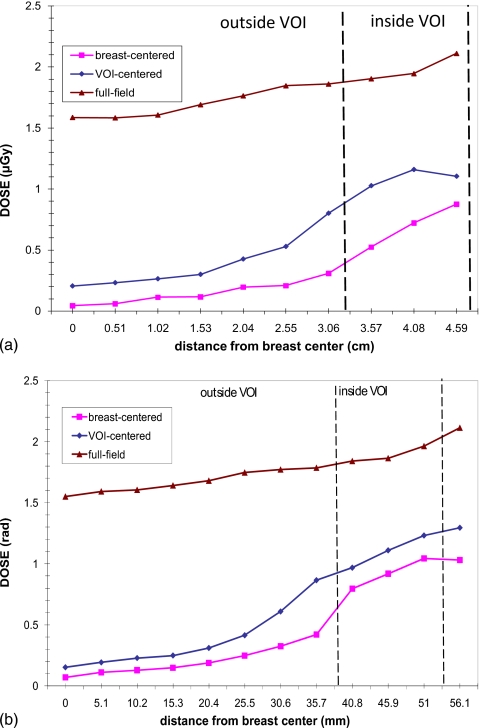
Figure 7 shows the radiation dose distributions as the function of radial distance (from the breast center to edge) in the breast phantom. Three plots represent the dose distributions of the breast-centered VOI approach, the VOI-centered VOI approach, and the breast-centered full field scan, respectively. It is found that both approaches significantly reduced the breast dose inside as well as outside the VOI. The doses inside the VOI were reduced by factors of 1.6 and 2.1 for VOI-centered and breast-centered approaches, respectively. As the distance from the VOI center increases, the dose reduction factor outside the VOI increased significantly from 2.8 to 21.1 for the breast-centered approach and from 2.0 to 11.3 for the VOI-centered approach.
Figure 7.
Dose profile along a radial line through the VOI center. The dashed line indicates the boundary of the VOI.
Comparison of breast-centered and VOI-centered approaches: Scatter reduction
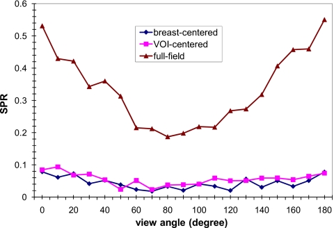
In Fig. 8, the scatter-to-primary ratios (SPRs) at the center of the VOI are plotted as a function of the view angle. The view angle ranged from 0° with the VOI closest to the x-ray tube to 180° with the VOI closest to the detector. It was found that in the full field image, the SPRs near 90° were lower than other views. The SPRs of both VOI approaches were substantially reduced and varied little with the view angle.
Figure 8.
SPR at the projected VOI center versus view angle. 0° and 180° correspond to the view with the VOI closest to the x-ray focal spot and the detector, respectively.
DISCUSSION
Our preliminary studies have demonstrated that the dual resolution CBCT technique can potentially be used to image small calcifications in a preselected VOI while reducing the dose both inside and outside the VOI.
The 160–180 μm MCs in the breast phantom could not be detected in the FP CBCT images, examples of which are shown in Fig. 6a[(1)–(4)]. The limited visibility may be due to the low spatial resolution and low achievable exposure level of the FP-based CBCT. The same group of MCs could be detected in the FP-CCD-based dual resolution CBCT images, examples of which are shown in Fig. 6b[(1)–(4)] and Fig. 6c[(1)–(4)]. This indicated that the low resolution and low dose projection data outside the VOI had little effect on the quality of the reconstructed image inside the VOI. The detectability of MCs was improved from 39% to 83% with increased number of projection views.
In this experiment, the reprojection method was adopted to generate projection data outside the VOI instead of the interpolation approach for several reasons. First of all, the angular position and the number of the projection views in the high resolution VOI scan may be different from those in the low resolution full field scan. The flexibility of reprojection can be used to match the number and angular position of the projection view and allow the low and high resolution projections to be combined with accuracy. Secondly, since the imaging geometry, including the orientation and positions of x-ray source, object, and detector could be modified to match with the experimental conditions of the VOI scan prior to the reprojection process, it may eliminate the need to do another scan even if those factors are different from the FP CBCT.
The VOI mask blocked the x-ray exposure in the region outside the VOI and reduced the scatter components both inside and outside the VOI, as shown in Fig. 8. This resulted in a significantly lowered breast dose both inside and outside the VOI, as shown in Fig. 7. This indicated that better image quality can be achieved with dual resolution scanning technique due to scatter reduction while substantially reducing dose both inside and outside the VOI.
The primary signals increased while the rotating angle increased from 0° to 90° due to decreasing x-ray penetration. Although more scatter interactions might happen close to 0° rotating angle projection, it was relatively difficult for scattered x rays to reach the detector due to longer x-ray path. This might result in no noticeable angular dependence of SPR with the VOI mask in Fig. 8.
The breast-centered approach has the advantages of being able to use the same imaging geometry as in full field scan. This greatly simplifies the task of combining the VOI scan data with the full field scan data prior to reconstruction. However, the disadvantage is that the VOI would appear at different locations and with variable sizes in the projection images as the view angle varies. Thus, a moving VOI mask and a moving high resolution detector are required to track and cover the VOI that moves in the projection images from one view angle to the next. This capability is currently being developed in our laboratory and demonstrated with a benchtop experimental system. The VOI-centered approach, on the contrary, has the advantage that the VOI stays stationary during the scan and therefore a stationary VOI mast can be used, eliminating the need to use a complex system involving the use of a moving VOI mask and a moving high resolution detector. The disadvantage, however, is the complexity in combining the full field scan data with the VOI scan data, which are acquired with the breast-centered geometry and the VOI-centered geometry, respectively.
There may also be differences in the breast dose and scatter signals with these two approaches. This has been investigated with Monte Carlo simulation in this study.
CONCLUSION
In this study, we investigated the feasibility of using the dual resolution CBCT technique to achieve high resolution CBCT images for preselected VOI. The detectability of the MCs inside the VOI was found to be improved with a FP-CCD detector-based CBCT system. With this technique, it is possible to selectively image a VOI with reduced breast dose and scatter effect. It was also found that the breast-centered VOI approach maybe preferred due to more dose saving.
ACKNOWLEDGMENTS
This work was supported in part by a research grant (Grant No. EB000117) from the National Institute of Biomedical Imaging and Bioengineering, a research grant (Grant No. CA104759), and a research grant (Grant No. CA124585) from the National Cancer Institute.
References
- Kopans D. B., Breast Imaging (Lippincott_Raven, Philadelphia, 1998). [Google Scholar]
- Bird R., Wallace T., and Yankaskas B., “Analysis of cancers missed at screening mammography,” Radiology 184, 613–617 (1992). [DOI] [PubMed] [Google Scholar]
- Lewin J. M., D’Orsi C. J., Hendrick R. E., Moss L. J., Isaacs P. K., Karellas A., and Cutter G. R., “Clinical comparison of full-field digital mammography and screen-film mammography for detection of breast cancer,” Am. J. Roentgenol. 179, 671–677 (2002). [DOI] [PubMed] [Google Scholar]
- S. J.DwyerIII, Boehme J. M., Cox G. G., Huynh P. T., Karellas A., Stewart B. K., Vannier M. W., and Williams M. B., “Computer applications and digital imaging,” Radiology 194, 616–618 (1995). [DOI] [PubMed] [Google Scholar]
- J. T.DobbinsIII and Godfrey D. J., “Digital x-ray tomosynthesis: Current state of the art and clinical potential,” Phys. Med. Biol. 48, R65–106 (2003). 10.1088/0031-9155/48/19/R01 [DOI] [PubMed] [Google Scholar]
- Wu T., Stewart A., Stanton M., McCauley T., Phillips W., Kopans D. B., Moore R. H., Eberhard J. W., Opsahl-Ong B., Niklas L., and Williams M. B., “Tomographic mammography using a limited number of low-dose cone-beam projection images,” Med. Phys. 30, 365–380 (2003). 10.1118/1.1543934 [DOI] [PubMed] [Google Scholar]
- Chang C., Sibala J., Fritz S., Gallagher J., S.DawyerIII, and Templeton A., “Computed tomographic evaluation of the breast,” Am. J. Roentgenol. 131, 459–464 (1978). [DOI] [PubMed] [Google Scholar]
- Chang C., Sibala J., Fritz S., Dwyer S., and Templeton A., “Specific value of computed tomographic breast scanner (CT∕M) in diagnosis of breast diseases,” Radiology 132, 647–652 (1979). [DOI] [PubMed] [Google Scholar]
- Gisvold J., Reese D., and Karsell P., “Computed tomographic mammography (CTM),” AJR, Am. J. Roentgenol. 133, 1143–1149 (1979). [DOI] [PubMed] [Google Scholar]
- John V. and Ewen K., “CT scanning of the breast in problem cases,” Strahlenther. Onkol. 133, 657–662 (1989). [PubMed] [Google Scholar]
- Boone J. M., Nelson T. R., and Lindfors K. K., “Dedicated breast CT: Radiation dose and image quality evaluation,” Radiology 221, 657–667 (2001). 10.1148/radiol.2213010334 [DOI] [PubMed] [Google Scholar]
- Ning R., Chen B., Conover D., McHugh L., Cullinan J., and Yu R., “Flat panel detector-based cone beam volume CT mammography imaging: Preliminary phantom study,” Proc. SPIE 4320, 601–610 (2001). 10.1117/12.430901 [DOI] [Google Scholar]
- Glick S., Vedantham S., and Karellas A., “Investigation of optimal kVp settings for CT mammography using a flat panel detector,” Proc. SPIE 4682, 392–402 (2002). 10.1117/12.465581 [DOI] [Google Scholar]
- Lai C.-J., Shaw C. C., Chen L., Altunbas M. C., Liu Xinming, Han T., Wang T., Yang W. T., Whitman G. J., and Tu S.-J., “Visibility of microcalcification in cone beam breast CT: Effects of x-ray tube voltage and radiation dose,” Med. Phys. 34, 2995–3004 (2007). 10.1118/1.2745921 [DOI] [PMC free article] [PubMed] [Google Scholar]
- Gong X., Vedula A. A., and Glick S. J., “Microcalcification detection using cone-beam CT mammography with a flat-panel imager,” Phys. Med. Biol. 49, 2183–2195 (2004). 10.1088/0031-9155/49/11/005 [DOI] [PubMed] [Google Scholar]
- Ning R., Conover D., and Yu Y., “Flat panel detector-based cone beam CT imaging: Preliminary system evaluation,” Proc. SPIE 5368, 616–620 (2004). 10.1117/12.536221 [DOI] [Google Scholar]
- Suryanarayanan S., Karellas A., Vedantham S., Sechopoulos I., and D’Orsi C. J., “Detection of simulated microcalcifications in a phantom with digital mammography: Effect of pixel size,” Radiology 244, 130–137 (2007). 10.1148/radiol.2441060977 [DOI] [PMC free article] [PubMed] [Google Scholar]
- Chen L., Shaw C. C., Altunbas M., Lai C.-J., Liu X., Han T., Wang T., Yang W., and Whitman G., “Feasibility of volume-of-interest (VOI) scanning technique in cone beam breast CT—a preliminary study,” Med. Phys. 35, 3482–3490 (2008). [DOI] [PMC free article] [PubMed] [Google Scholar]
- Karellas A., Harris L. J., Liu H., Davis M. A., and D’Orsi C. J., “Charge-coupled device detector: Performance considerations and potential for small-field mammographic imaging applications,” Med. Phys. 19, 1015–1023 (1992). 10.1118/1.596819 [DOI] [PubMed] [Google Scholar]
- Hejazi S. and Trauernicht D. P., “System considerations in CCD-based x-ray imaging for digital chest radiography and digital mammography,” Med. Phys. 24, 287–297 (1997). 10.1118/1.598072 [DOI] [PubMed] [Google Scholar]
- Vedantham S., Karellas A., Suryanarayanan S., Levis I., Sayag M., Kleehammer R., Heidsieck R., and D’Orsi C. J., “Mammographic imaging with a small format CCD-based digital cassette: Physical characteristics of a clinical system,” Med. Phys. 27, 1832–1840 (2000). 10.1118/1.1286720 [DOI] [PMC free article] [PubMed] [Google Scholar]
- Cho S., Bian J., Pelizzari C. A., Chen C.-T., He T.-C., and Pan X., “Region-of-interest image reconstruction in circular cone-beam microCT,” Med. Phys. 34, 4923–4933 (2007). 10.1118/1.2804924 [DOI] [PubMed] [Google Scholar]
- Hsieh J., Chao E., Thibault J., Grekowicz B., Horst A., McOlash S., and Myers T. J., “A novel reconstruction algorithm to extend the CT scan field-of-view,” Med. Phys. 31, 2385–2391 (2004). 10.1118/1.1776673 [DOI] [PubMed] [Google Scholar]
- Zou Y., Pan X., and Sidky E. Y., “Image reconstruction in regions of interest from truncated projections in a reduced fan-beam scan,” Phys. Med. Biol. 50, 13–27 (2005). 10.1088/0031-9155/50/1/002 [DOI] [PubMed] [Google Scholar]
- Clackdoyle R., Noo F., Guo J., and Roberts J. A., “Quantitative reconstruction from truncated projections in classical tomography,” IEEE Trans. Nucl. Sci. 51, 2570–2578 (2004). 10.1109/TNS.2004.835781 [DOI] [Google Scholar]
- Pack J. D., Noo F., and Clackdoyle R., “Cone-beam reconstruction using the backprojection of locally filtered Projections,” IEEE Trans. Med. Imaging 24, 70–85 (2005). 10.1109/TMI.2004.837794 [DOI] [PubMed] [Google Scholar]
- Noo F., Clackdoyle R., and Pack J. D., “A two-step Hilbert transform method for 2D image reconstruction,” Phys. Med. Biol. 49, 3903–3923 (2004). 10.1088/0031-9155/49/17/006 [DOI] [PubMed] [Google Scholar]
- Patel V., Hoffmann K. R., Ionita C. N., Keleshis C., Bednarek D. R., and Rudin S., “Rotational micro-CT using a clinical C-arm angiography gantry,” Med. Phys. 35, 4757–4764 (2008). 10.1118/1.2989989 [DOI] [PMC free article] [PubMed] [Google Scholar]
- Feldkamp L. A., Davis L. C., and Kress J. W., “Practical cone-beam algorithm,” J. Opt. Soc. Am. A 1, 612–619 (1984). 10.1364/JOSAA.1.000612 [DOI] [Google Scholar]
- Boone J. M., Shah N., and Nelson T. R., “A comprehensive analysis of DgN(CT) coefficients for pendant-geometry cone-beam breast computed tomography,” Med. Phys. 31, 226–235 (2004). 10.1118/1.1636571 [DOI] [PubMed] [Google Scholar]
- Han T., Shaw C. C., Chen L., Lai C.-J., Liu X., and Wang T., “Simulation of mammograms and tomosynthesis imaging with cone beam breast CT images,” Medical Imaging 2008: Physics of Medical Imaging (SPIE, Bellingham, WA, 2008), Vol. 6913, pp. 691317–691317.
- Siddon R. L., “Fast calculation of the exact radiological path for a three-dimensional CT array,” Med. Phys. 12, 252–255 (1985). 10.1118/1.595715 [DOI] [PubMed] [Google Scholar]
- Galigekere R. R., Wiesent K., and Holdsworth D. W., “Cone-beam reprojection using projection-matrices,” IEEE Trans. Med. Imaging 22, 1202–1214 (2003). 10.1109/TMI.2003.817787 [DOI] [PubMed] [Google Scholar]
- Agostinelli S. et al. , “GEANT4—a simulation tool kit,” Nucl. Instrum. Methods Phys. Res. A 506, 250–303 (2003). 10.1016/S0168-9002(03)01368-8 [DOI] [Google Scholar]
- Hammerstein G. R., Miller D. W., White D. R., Masterson M. E., Woodard H. Q., and Laughlin J. S., “Absorbed radiation dose in mammography,” Radiology 130, 485–491 (1979). [DOI] [PubMed] [Google Scholar]


