Abstract
A peristaltic micropump was fabricated and characterized. The micropump was fabricated using soft lithography, and actuated using piezoelectric bimorph cantilevers. The micropump channel was formed by bonding two layers of PDMS, mixed at 5 : 1 and 30 : 1 ratios. The channel was fabricated in the 5 : 1 layer using replica molding (REM), where a very simple and inexpensive template was made by straddling a 75 μm wire over a glass substrate, followed by covering and smoothing over the wire with a piece of aluminium foil. Not only was this template inexpensive and extremely simple to fabricate, it also created a rounded cross-sectional geometry which is favorable for complete valve shutoff. The cantilevers were driven at V p = ±90 V with amplified square wave signals generated by a virtual function generator created in LabVIEW. Connections to the micropump were made by placing capillary tubes in the channel, and then sealed between the two layers of PDMS. Machined aluminium clamps were adhered to the tips of the cantilevers with general purpose adhesive. These clamps allowed for aluminium valves, with finely machined tips of dimensions 3 mm by 200 μm, to be held firmly in place. The variables characterized for this micropump were flow rate, maximum attainable backpressure, free cantilever deflection, valve shutoff, and valve leakage. Three actuation patterns with phase differences of 60, 90, and 120° were compared for flow rate and maximum backpressure. It was determined that the 120° signal outperformed the 60° and 90° signals for both maximum flowrate and maximum attainable backpressure. The maximum and minimum flowrates demonstrated by the micropump were 289 nL min−1 and 53 nL min−1, respectively. The maximum backpressure attained was 35 300 Pa. It was also demonstrated that the valves fully closed the channels upon actuation, with minimal observed leakage.
Introduction
An important aspect in the design of any microfluidic device is the method used to transport fluids through the device’s internal conduits. Micropumps are commonly used for this purpose. Micropumps in the literature have generally been classified according to one of two schemes. The first is to classify a pump as either mechanical or non-mechanical (i.e. with or without moving parts).1,2 The more recently suggested method is to classify pumps as either displacement or dynamic.3 Displacement pumps exert pressure forces on working fluids through one or more moving boundaries, where dynamic pumps continuously add energy to a working fluid in a manner that increases either its momentum or its pressure directly.3 The majority of micropumps in the literature fall into the displacement category, where the moving boundary is a reciprocating diaphragm. Deflection of these pump diaphragms has been accomplished using many different types of actuators including pneumatic,4,5 thermopneumatic,6,7 electrostatic,8,9 electromagnetic,10,11 shape-memory alloy,12 and piezoelectric.13,14 The choice of which actuation method to use in displacement and dynamic pumps depends on many variables including the working solution, size, power consumption, flow rate, frequency, and backpressure needs. The reader is referred to several excellent references that describe the pros and cons of each actuation principle for state-of-the-art micropump technology.1–3,15–17
One relatively unexplored actuation method for soft vpolymer-based micropumps is the use of piezoelectric materials. Piezoelectricity is a physical phenomena where a material will produce an electric charge when stressed mechanically, or produce a dimensional change when stressed electrically with a voltage.18 These materials are widely used for many sensing and actuator applications. The most common piezoelectric elements used for micropump applications are either rectangular bimorph (two-layers of piezoelectric material) cantilever beams or circular discs, both being made from a ceramic compound called PZT (lead zirconate titanate). Dimensions for these actuators vary depending on performance requirements, but can be as large as several centimetres for microdevice applications. One or more disks or cantilevers can be used to actuate a diaphragm. A single cantilever or disc is often used with check valve pumps, where the valves are passive and respond to pressure changes within the pump chamber. In other designs, piezoelectric elements can be combined in series to form peristaltic pumps. The series configuration of actuators in effect creates a pump with multiple chambers. By actuating the piezoelectric elements in series, a wavelike motion is created that propels solution with a net motion in one direction.
For this work, a peristaltic micropump was fabricated from PDMS and glass using soft lithography. A novel method was used to fabricate a simple, quick, and inexpensive template for prepolymer molding. This method also produces a cross sectional geometry that is favorable for increased device performance. Actuation of the micropump was performed using piezoelectric cantilevers. Aluminium clamps were adhered to the tips of the cantilevers, to hold precisely machined aluminium masses in place that served as valves for the micropump. Strict control of registration for the valves over the channel was made possible with the aid of in-house manufactured micropositioners. The performance variables characterized for this micropump were flow rate, valve closure, valve leakage, and maximum backpressure.
Experimental methods
Design
The peristaltic micropump, valves, and valve clamps are shown in Fig. 1A–C. The micropump is composed of a PDMS channel layer placed on a glass substrate, as shown in Fig. 1C. Three piezoelectric cantilevers are mounted on anodized aluminium micropositioners that allow for individual control of the horizontal and vertical position as well as the tilt of the valve tips. Adhered to the ends of the cantilevers are aluminium clamps, that hold aluminium valve tips in place that can be actuated to open and close the channel. A close up view of the clamps and valves can be seen in Fig. 1B, and a cross sectional schematic of the valve tips can be seen in Fig. 1A.
Fig. 1.
Image of the micropump, micropositioners, and valves. (A) The cross-sectional geometry of the valve. The width of the microvalves was 200 μm, and the length was 3 mm. (B) A close-up image of the valve clamps used to secure the valves in place. (C) The full micropump design with the micropositioners, piezoelectric cantilevers, and PDMS channel structure on a glass substrate.
Fabrication
PDMS channel and base layers
The micropump is composed of a single channel fabricated in PDMS. Fabrication begins with the creation of the master template. The template was formed by wrapping a 75 μm wire over a clean glass substrate, where the ends of the wire were adhered to the underside using Scotch tape. A thin layer of general purpose adhesive was then sprayed across the top of the glass surface. Aluminium foil was placed over the glass surface, in effect sandwiching the metal wire between the glass and aluminium foil. The aluminium was then gently smoothed over the wire using finger pressure to remove any air pockets. To complete the process, a square Teflon block with a carved out “C” was used to further smooth the aluminium foil. The narrow edge of the Teflon block was used to press the foil tightly against the covered metal wire.
After the template mask was fabricated, PDMS prepolymer (GE, RTV 615) was mixed in a 5 : 1 ratio and poured over the surface of the mask. Rectangular plastic spacers (~203 μm in height) were placed at the edges of the template to control the PDMS layer thickness. Next, a clean glass wafer was laid onto the mask surface with prepolymer and plastic spacers, to create a “sandwich” of PDMS. Gentle pressure was applied to both mask and glass wafer to extrude excess PDMS. Before heat curing, general laboratory tape was adhered to the top and bottom sandwich substrates to hold the two substrates in place. The PDMS sandwich was cured in a convection oven at 80°C for one or more hours. The 5 : 1 ratio yields a relatively firm PDMS layer that accurately reproduces the rounded shape of the template and is resistant to damage when compressed by the metal tip of the actuator.
Fabrication of the second PDMS layer was similar. Prior to mixing the second layers prepolymer PDMS at a 30 : 1 ratio, two clean glass wafers were placed in a desiccator with tridecaflu-orooctyltrichlorosilane vapor (United Chemical Technologies, model T2492) for 1–2 h to reduce adhesion of the PDMS to the glass substrates. After removing the wafers from the desiccator, plastic spacers measuring ~203 μm were placed on one of the glass substrates to control the PDMS layers thickness. The 30 : 1 PDMS prepolymer was then poured over the glass surface, with subsequent addition of the second glass substrate to sandwich the 30 : 1 PDMS. Gentle pressure was applied to the glass substrates to extrude excess PDMS, and tape adhered to top and bottom glass substrates to hold them in place while curing. A partial cure of the 30 : 1 PDMS was performed in a convection oven for 45 min. The 30 : 1 ratio gives a more flexible, tackier PDMS layer that ensures a good seal with the channel layer.
Fused silica capillary (Polymicro, 105 μm outer diameter/40 μm inner diameter) was used to make connections to the micropump. After separating the fully cured 5 : 1 wire imprinted PDMS sandwich, two ~30 cm long pieces of capillary tubing were placed approximately 1.5 cm into the PDMS channel. When the capillary tubes were properly aligned, a fresh 5 : 1 PDMS mixture was placed along the capillary tube in the channel to seal the void areas between the channel and tubing. At this point the partially cured 30 : 1 sandwich was separated and placed over the 5 : 1 layer with the capillary tubes in place. A heat cure was performed at 80°C for one or more hours to irreversibly bond the two layers. After removal of the sealed PDMS channel from the convection oven, another fresh mixture of 5 : 1 PDMS was applied to the outer regions where the capillary tubes exit the PDMS, and cured again at 80°C for one or more hours. The 30 : 1 layer served as the base layer, where the 5 : 1 layer with the embossed wire-mold channel served as the membrane for the micropump. The membrane at its thinnest point measured ~140–145 μm.
Valves and valve clamps
Aluminium valve clamps were adhered to the tips of the piezoelectric cantilevers (see Fig. 1B). The valves for the piezoelectric cantilevers were fabricated from rectangular aluminium blocks using an electrical discharge machine (EDM). At one end of the blocks was a finely machined protruding structure (see Fig. 1A), with a cross sectional geometry resembling that of an obelisk. The protruding structures served as the valve tips that made contact with the PDMS membrane surface. The PDMS contact area of the valve tips were machined with a length and width of 3 mm and 200 μm, respectively.
Cantilevers, stabilizer blocks, and micropositioners
Piezoelectric cantilevers were purchased from Piezo Systems (Q220-A4–303YB). This model cantilever comes with the PZT actuator bonded to a general quick mount system, with prewired electrical connections. In order to mount the cantilevers into the micropositioners and protect the cantilevers from being damaged, approximately 12 mm × 6 mm × 3.5 mm (L × W × H) acrylic blocks were hand machined and adhered to the top of the quick mounts. Printed circuit board (PCB) material was hand machined and bonded to the bottom of the quick mount cantilevers. Both PCB and acrylic mounts were bonded to the quick mounts with a general purpose silicone adhesive (see Fig. 1C).
Micropositioners that allowed for adjustment of the valve position were fabricated in the Electrical Engineering Machine Shop at the University of Minnesota. Hand-turned adjustments were made possible with two manual micropositioning stages (Edmond Scientific, #56–416) and one metal hinge. The design of the micropositioners allowed for adjustments to be made horizontally (in/out), vertically (up/down), and tilt (up/down). The bulk material that the micropositioners were made from was anodized aluminium, to prevent any potential arcing from the cantilevers to the micropositioners. Metal screws were used to hold the cantilevers in place, where plastic screws were used to hold the micropositioners to the glass substrate where the PDMS channel resided. The micropositioners with the cantilevers and mounts can be seen in Fig. 1C.
Software and hardware
A virtual function generator was created using National Instruments software and a data acquisition card (PCI-6259). The function generator had controls for signal type, frequency, amplitude, and phase adjustments. Three channels with individual phase adjustment were necessary to deliver signals to the cantilevers that would create a peristaltic motion. Actuation signals with phase differences of 60, 90, and 120° were compared with respect to flow rate and maximum attainable backpressure. Fig. 2 illustrates the three valve sequences for the 60, 90, and 120° signals.
Fig. 2.
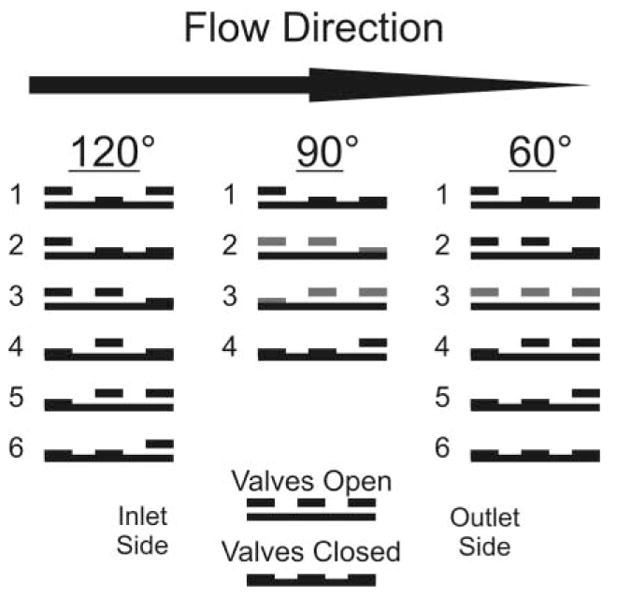
Signal sequence for peristaltic micropump valves. Three unique square wave signal sequences are possible by varying the phase of the signal sent to each of the cantilever actuators. These three signal sequences can be referred to with respect to their phase variations of 120, 90, and 60°.
In-house electronic hardware was fabricated to drive the piezoelectric cantilever actuators. High voltage amplifiers (Apex Microtechnology, PA15A) were used to amplify square waves generated by the virtual function generator to V p = ±90 V, which was the maximum allowable driving potential for the cantilevers.
Characterization experiments
Valve alignment
With the cantilevers connected to the micropositioners, and the micropositioners connected to the glass substrate containing the PDMS channel, the valves were aligned over the channel using a microscope. The valves were aligned such that they were directly over the channel membrane, so that when actuated in the down position, the channel was completely closed off from fluid flow in either direction. Valves not completely closing off flow (i.e. not 100%) were easily spotted using either fluorescence detection under the valves, or by observing cavitation, where bubbles would form in the channel under or adjacent to the valve.
Flow rate
Flow rates were characterized by tracking the linear flow velocities of a small bubble introduced into the outlet line of the micropump, using distilled water as the working solution. Tracking the bubbles velocity over time allowed for a flow rate to be calculated using the formula Q = Av, where Q is the flow rate, A is the cross sectional area, and v = linear flow velocity. The flow rate was characterized for signals with phase differences of 60, 90, and 120°. The standard errors were calculated and plotted as error bars for each set (n = 4) of flow rate measurements taken at each frequency.
Maximum backpressure
Backpressure measurements were taken by connecting the micropump outlet to an electronic pressure sensor (Honeywell, 40PC015G2A), that previously had its internal cavity completely filled with distilled water. The micropump was actuated to flow solution towards the pressure transducer. The pressure was monitored over time until a stable reading was obtained. The maximum attainable backpressure was characterized for actuation sequences with phase differences of 60, 90, and 120°.
Valve deflection and valve shutoff cycle
Valve deflection was measured by placing a micropositioner on its side and recording the no-load displacement of the valve at 30 V intervals from −90 V to 90 V. Displacement values were recorded using a microscope with an embedded optical reticle placed in the eyepiece of the microscope.
Valve shutoff data were collected independently from the valve deflection measurements. The collection of valve shutoff data began by placing the micropump in an inverted position, so that the PDMS channel under the valves was visible through an epifluorescence microscope. A working solution was flowed through the micropump using a syringe pump. After stopping the syringe pump, the solution was allowed to dissipate from the micropump’s outlet for 30 s, when after this time the outlet was capped off to prevent any further loss of solution. Intensity values were recorded for both distilled water and a 1 mM fluorescein solution, where these data were collected at 30 V intervals from −90 V to 90 V using a CCD camera. The background signal for the distilled water was subtracted from the fluorescein signal, where quantification of the signal intensities was performed using Metavue software.
Valve leakage
Experiments to measure valve leakage began by filling the micropump with distilled water using a syringe pump. After the microchannel was filled, the inlet of the micropump was disconnected from the syringe pump and placed into a water-filled reservoir. The pump outlet was then connected to a pressure sensor that had been previously filled with distilled water. The pump was operated at 40 Hz with a 120° signal, until the pressure stabilized at its maximum attainable value. After the backpressure stabilized, actuation of the cantilevers was stopped and the inlet of the micropump was removed from the reservoir, and laid on a flat surface. The cantilevers were then individually actuated with dc signals, so that two valves were in the open position, while one remained closed. Pressure measurements were recorded for 10 min with one valve closed, to examine pressure loss in the system. After the 10 min observation period, the pressure drop was recorded as the closed valve was opened.
Results and discussion
Design
Peristaltic design
Peristaltic pumps have several inherent advantages over other pump designs. Unlike micropumps that utilize check valve designs, peristaltic pumps usually involve a simpler design and fabrication process. For example, the micropump described for this work requires only one simple template, and no photolithography mask for fabrication of the PDMS channel, where other pumps made from PDMS require two or more templates and photolithographic masks.4,19 Devices that require two or more masks for fabrication can also have a difficult and/or complicated registration process for aligning multiple layers of PDMS.19 Two other favorable design aspects for peristaltic pumps with designs similar to the one described in the work are; (1) insensitivity to the working solution, and (2) little or no dead volume associated with the valving region.
Piezoelectric actuation and cantilever valves
Piezoelectric actuation is a well-suited method for many micropump designs. This method of actuation has been widely utilized with glass and silicon-fabricated micropumps, but has remained a relatively unexplored actuation method for soft polymer-based micropumps. Piezoelectric actuators made from PZT can generate some of the largest actuation forces for all types of external actuators used in micropumps. PZT actuators also have some of the fastest response times, and are not limited to external on/off switching equipment like many pneumatic designs. Deflection displacement can be very large in comparison to other actuation methods, where less than 100 μm of free deflection is typical. Theoretical displacement values for the cantilevers used in this work is 630 μm.18 Lastly, external actuators like piezoelectric cantilevers allow for a partially disposable device design, where the actuators can be used repeatedly for disposable PDMS fabricated microchannel structures.
In spite of the many advantages piezoelectric actuators possess, this method of actuation, like that of all other methods, is not ideal in every way. The biggest disadvantage of using external piezoelectric actuators is their physical size. This property does not allow for an extremely high density of addressable valves like that of some pneumatic designs.5,20 The up-front design work in using piezoelectric actuators is also likely more complex and costly than most pneumatic designs, when in-house micropositioners are utilized for valve alignment. While it is possible to utilize primitive fixed-in-place clamping methods for valve alignment, it is highly advantageous to use micropositioning devices. Once fabricated, micropositioner devices have the advantages of being reusable, and highly reproducible. Registration of valves over microchannels is also very quick and effortless. This may not always be the case with pneumatic designs, where alignment of a second PDMS valving layer over PDMS flow channels is required. Both the micropositioners and the precision-machined valves for this pump can provide the user with flexible options to modify the flow and valving characteristics of the pump. Only one valve-tip dimension was used for this micropump, however it is possible to fabricate other valves with different dimensions to tailor a micropump’s flow and valving conditions to any specific device.
Fabrication
Replica molding (REM) template
The most common method for fabricating mask templates for the purpose of replica molding is to use soft lithography rapid prototyping methods.21 This process creates a mylar mask using computer-aided drafting (CAD) software and high resolution printers. Typically, the mylar mask is used in a clean room, where photolithography is performed for creation of bas-relief structures. The use of clean-room equipment can be expensive, and also requires the user to develop photolithography processing protocols. However, creation of master templates using photolithography has the advantage of allowing for complex and dense structures to be patterned.
In certain instances where simple structures such as long channels or flow crosses are needed for replica molding, it may not always be necessary to use clean-room equipment for template creation.22–24 This was the case for this work. Template creation required very inexpensive and accessible supplies such as aluminium foil, glass, general purpose adhesive, small-gauge wire, and a soft plastic material such as Teflon. The simple nature of the template design eliminated the need for use of CAD software. While the method used for template creation in this work is limited to fabrication of simpler structures, it still has the advantages of being considerably faster, easier, and cheaper than using photolithography equipment in a clean room. It is conceivable this aluminium foil-wire template process could also be automated, as a result of the very simple template designs. Machines could use CAD file designs to lay wire down onto an adhesive surface, where the aluminium foil could be vacuum sealed over the wire. Another possibility would be to use the aluminium foil-wire template process in mix-and-match lithography. Complex design layers could be fabricated using templates created from traditional photolithography masks, where the simpler design layers could be created from templates fabricated using the aluminium foil-wire template process.
One last advantage of the template fabrication process described for this work has to do with the cross-sectional geometry of the channel. The rounded channel geometry produced for this work can be seen in Fig. 3. It has been shown that a rounded channel geometry is favorable for valving processes on microfluidic chips.4 It is also common to find other applications that benefit from creation of microstructures with a rounded profile.25–27
Fig. 3.
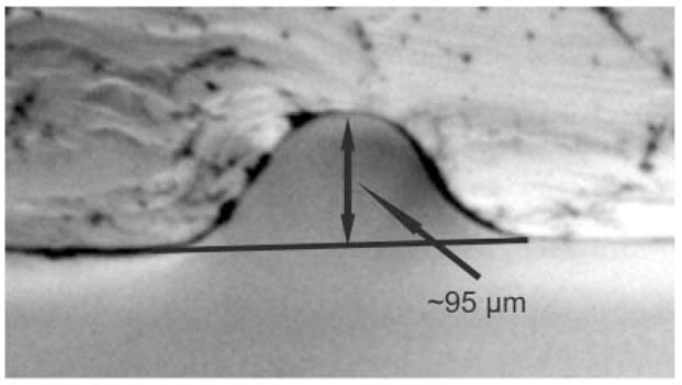
Cross-sectional image illustrating the PDMS channel geometry. A smoothly rounded channel is produced using the aluminium foil/wire molding process.
Flow rate
The effect of actuation frequency on flow rate is shown in Fig. 4. Actuation signals varying in phase by 60, 90, or 120° are also compared. All three curves demonstrate an initial sharp increase in flow rate, followed by a frequency range where flow rates increase linearly, and then either start to drop off (120° & 60°) or continue to increase slowly (90°). The overall trend in the magnitude of flow rates (120° > 90° > 60°) can be explained with a closer examination of Fig. 2. For the 120° signal, there is no point throughout the actuation cycle where at least one valve is not completely closed. For the 90° signal, as pressure builds at the outlet, backflow can occur between steps 2 and 3 when the outer valves change from open to closed, and closed to open, respectively. The situation is even more extreme in the 60° pattern, where in step 3 all three valves are open, allowing for complete backflow from outlet to inlet as pressure builds on the outlet side of the pump.
Fig. 4.
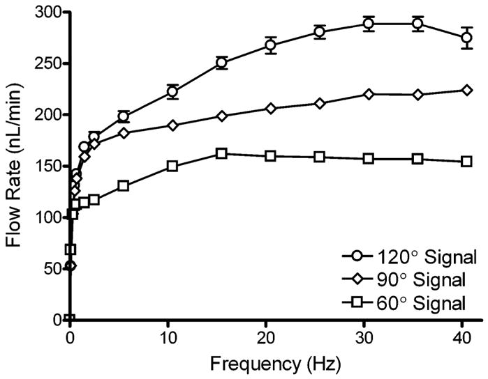
Effect of actuation frequency on flow rate generated by the micropump. Actuation signals with 120°, 90°, and 60° phases were compared. Flow rate was measured by tracking the linear velocity of a small bubble introduced into the capillary attached to the micropump outlet. Error bars are the standard error of the mean (n = 4).
The largest range of flow rates was observed for the 120° signal, which varied from 53–289 nL min−1 (0.1–35 Hz). The ranges for the 90° and 60° signals were 53–224 nL min−1 (0.1–40 Hz) and 69–162 nL min−1 (0.1–15 Hz), respectively. Regions of each flow curve yielded very linear data. The 120° signal was linear from 2–20 Hz (178–268 nL min−1), with an R2 value of 0.9913. The 90° signal was linear from 5–30 Hz (182–220 nL min−1) with R2 = 0.9943. And lastly, the 60° signal was linear from 0.7–10 Hz (113–150 nL min−1) with R2 = 0.9962. The stability and reproducibility of these flow rate data makes this pump an ideal candidate for applications that require microdosing or microinjecting functions. The large range of frequency operation also allows users to more easily fine-tune desired flow rates, as opposed to other actuation methods such as thermopneumatic designs, where frequency of operation is limited to only a few Hertz. While no data were collected for flow in the opposite direction, the micropump was tested, and easily reverses flow simply by inverting the signal sequence delivered to the cantilevers.
Flow rate data for each signal pattern were only collected up to 40 Hz. Above 40 Hz, the micropositioners had a tendency to vibrate out of place, moving the valves out of alignment over the channel. At frequencies higher than 40 Hz, flow rates decreased. Using a microscope, cross-sectional examination of the micropump cantilevers with a PDMS channel under the valves, reveals a sharp decrease in amplitude from 50–52 Hz. These data suggest that there is a physical response time limitation of the cantilevers themselves to fully respond to the input signals. However, this explanation cannot account for the flow rate data between 40 and 50 Hz, where flow rates start to decrease. A possible explanation would be that there is another response time limitation associated with the PDMS membrane, where above 40 Hz the membrane below the valve is not able to fully relax before the valve recloses the channel. The observation of cantilever deflection with PDMS channels below the valves also indicates that possible resonant frequencies exist at 33, 36, and 49 Hz.
Valve deflection and valve shutoff cycle
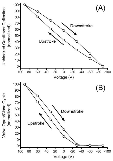
Valve performance in any pump is very important. Valves must reliably block backflow, as even the smallest amount of leakage could detrimentally affect device performance. The deflection of the cantilever with zero load was measured to serve as a comparison to the situation where the cantilever movement was subjected to a load (i.e. closing off the PDMS channel). As shown in Fig. 5A, the cantilevers have an inherent hysteresis associated with their deflection. The data for experiments where a PDMS channel is placed below the valves are shown in Fig. 5B. The fluorescent signal detected in the channel is nearly zero at voltages less than −30 V, supporting the conclusion that the valve fully closes off the channel, impeding flow of channel contents in either direction.
Fig. 5.
(A) The deflection of an unblocked cantilever was measured with an optical reticle, by recording its displacement horizontally under a microscope. (B) The microvalve open/close cycle was recorded by filling the micropump with a fluorescein solution using a commercial syringe pump. After filling the micropump, a plug was placed over the outlet line of the micropump, trapping the fluorescein solution inside the micropump channel. Fluorescence intensity was then recorded using an epifluorescence microscope at various points throughout the actuation cycle. The data shown here are from a single representative experiment.
Valve leakage
Another important performance metric for which pumps are evaluated is their valve leakage. The leakage of a valve can be improved by three to four orders of magnitude through the use of soft materials such as PDMS when compared to devices fabricated in hard materials such as silicon, glass or silicon nitride.1 The use of PDMS for the channel, combined with the high pressure resulting from the large force generated by the piezoelectric cantilevers applied to the small surface area of the valve tips, would be expected to minimize the potential for leakage through the valve when closed. Fig. 6 demonstrates the ability of a single closed valve to effectively seal the channel while under pressure. One valve in the closed position was able to hold a pressure of 36 700 Pa, where only a 2% pressure loss (827 Pa) was observed over ten minutes. It is believed that much of this pressure loss occurred at connections between the outlet of the micropump and the pressure sensor, since no backflow was observed through the valve. After ten minutes the piezoelectric actuator was opened and the rate of pressure loss increased 41-fold as fluid flowed through the open valve.
Fig. 6.
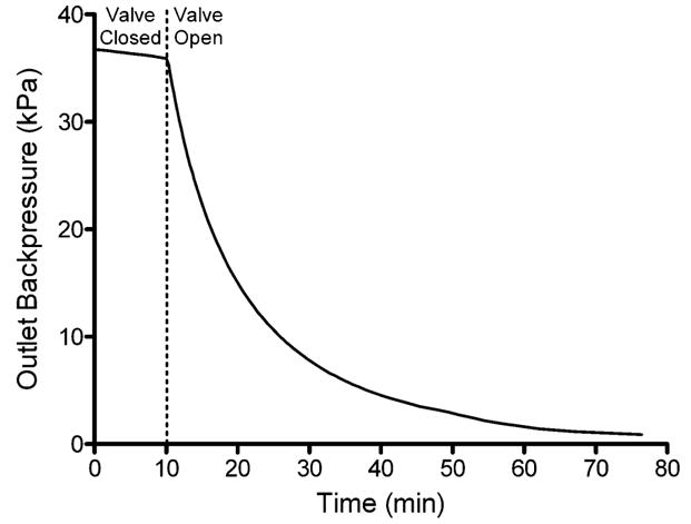
Micropump valve shutoff/leakage curve. The micropump was allowed to fully pressurize the outlet line connected to a pressure sensor. Actuation was then stopped in a position with a single valve in the fully closed position. Pressure measurements were monitored for ten minutes to monitor leakage through the closed valve. After ten minutes the closed valve was opened and further pressure measurements were obtained for the depressurization of the outlet line. The rate of pressure loss increased 41-fold when the valve was opened. The data shown here are from a single representative experiment.
Maximum attainable backpressure
The effect of frequency and the phase of the actuation signal on the maximum attainable backpressure of the micropump was investigated (see Fig. 7). It can be observed that the trend in the magnitudes of the backpressure was 120° > 90° > 60° for all frequencies. This trend can be explained by the potential for solution backflow when using the 60° and 90° signals, as discussed in the flow rate section above. The overall trend for the 120° and 90° signals was to increase to their maximum values of 35 300 Pa and 28 000 Pa respectively. For the 60° signal, maximum backpressure stabilized at 15 Hz, maintaining a pressure between 19 700–20 000 Pa up to 40 Hz. The backpressures this micropump can work against are higher than most previously reported peristaltic micropumps.1,3 The large actuation force generated using external piezoelectric cantilevers, in conjunction with the small contact surface area of the valves with the PDMS membrane, make it possible for the valves to generate very large pressures that are able to fully close even when the valves are working against large backpressures. The high backpressures this pump can work against make it suitable for in vivo drug delivery applications, where it has been reported in vivo backpressures can be as high as 25 000 Pa.3
Fig. 7.
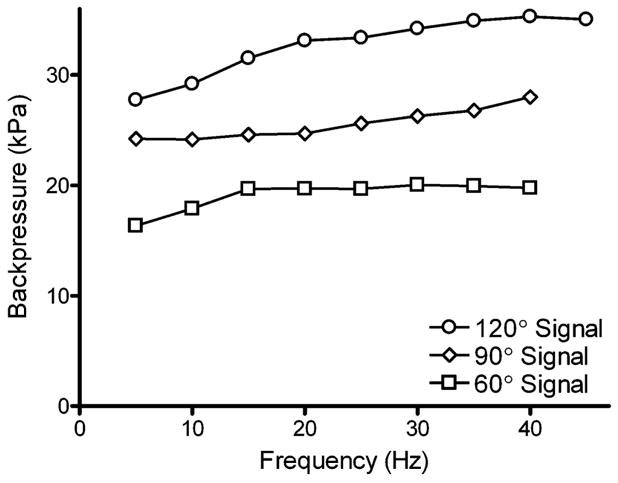
Effect of actuation frequency on maximum attainable back-pressure. Actuation patterns with phase differences of 120°, 90° and 60° were compared. Backpressure was measured by connecting an electronic pressure sensor to the outlet line of the micropump. The data shown here are from a single representative experiment.
Conclusions
In conclusion, we have fabricated a piezoelectric bimorph cantilever-actuated peristaltic micropump using soft lithography. The template fabrication method used for this work was extremely simple, cheap, and generated rounded cross-sectional geometries that are favorable for complete valve shutoff. The performance reported here suggests that this micropump is very robust and suitable for integration into many microfluidic device platforms. Flow rates are very reproducible, where measurements show little standard error at each frequency. Valve data indicate little if any backflow occurs across the valves, even when working against high back pressures. The alignment of the valves was also quick and effortless with the aid of machined micropositioners. The backpressures this micropump can work against show that it falls within the upper tier of what most micropumps are capable of generating. It was also demonstrated that the phase of the actuation signal was very important to overall performance of the micropump’s flow rate and maximum attainable backpressure.
Acknowledgments
We would like to thank the machinists in the Electrical Engineering Machine Shop at the University of Minnesota, especially Dave Hultman for his helpful suggestions and insight that went into the fabrication of the micropositioners. This work was supported by NIH grant NS043304.
References
- 1.Nguyen N-T, Wereley ST. Fundamentals and Applications of Microfluidics. Artech House; Norwood, MA: 2002. [Google Scholar]
- 2.Shoji S, Esashi M. J Micromech Microeng. 1994;4:157–171. [Google Scholar]
- 3.Laser DJ, Santiago JG. J Micromech Microeng. 2004;14:35–64. [Google Scholar]
- 4.Unger MA, Chou HP, Thorsen T, Scherer A, Quake SR. Science. 2000;288:113–116. doi: 10.1126/science.288.5463.113. [DOI] [PubMed] [Google Scholar]
- 5.Grover WH, Skelley AM, Liu CN, Lagally ET, Mathies RA. Sens Actuators, B. 2003;89:315–323. [Google Scholar]
- 6.Handique K, Burke DT, Mastrangelo CH, Burns MA. Anal Chem. 2001;73:1831–1838. doi: 10.1021/ac000711f. [DOI] [PubMed] [Google Scholar]
- 7.Jeong OC, Park SW, Yang SS, Pak JJ. Sens Actuators, A. 2005;A123–A124:453–458. [Google Scholar]
- 8.Machauf (Prochaska) A, Nemirovsky Y, Dinnar U. J Micromech Microeng. 2005;15:2309–2316. [Google Scholar]
- 9.Xie J, Shih J, Lin Q, Yang B, Tai YC. Lab Chip. 2004;4:495–501. doi: 10.1039/b403906h. [DOI] [PubMed] [Google Scholar]
- 10.Santra S, Holloway P, Batich CD. Sens Actuators, B. 2002;B87:358–364. [Google Scholar]
- 11.Pan T, McDonald SJ, Kai EM, Ziaie B. J Micromech Microeng. 2005;15:1021–1026. [Google Scholar]
- 12.Benard WL, Kahn H, Heuer AH, Huff MA. J Microelectromech Syst. 1998;7:245–251. [Google Scholar]
- 13.Koch M, Harris N, Evans AGR, White NM, Brunnschweiler A. Sensors and Actuators, A: Physical 9th International Solid State Sensors and Actuators Conference (Transducers ’97); 16–19 June 1997; Chicago, IL: Elsevier; 1998. pp. 98–103. [Google Scholar]
- 14.Jang LS, Li YJ, Lin SJ, Hsu YC, Yao WS, Tsai MC, Hou CC. Biomed Microdevices. 2007;9:185–194. doi: 10.1007/s10544-006-9020-8. [DOI] [PubMed] [Google Scholar]
- 15.Nguyen NT, Huang X, Chuan TK. J Fluids Eng. 2002;124:384–392. [Google Scholar]
- 16.Singhal V, Garimella SV, Raman A. Appl Mech Rev. 2004;57:191–221. [Google Scholar]
- 17.Woias P. Sens Actuators, B. 2005;B105:28–38. [Google Scholar]
- 18.Catalog #7B, Piezo Systems Inc., Cambridge, MA, 2008, www.piezo.com/catalog7B.pdf.
- 19.Jeon NL, Chiu DT, Wargo CJ, Wu H, Choi IS, Anderson JR, Whitesides GM. Biomed Microdevices. 2002;4:117–121. [Google Scholar]
- 20.Thorsen T, Maerki SJ, Quake SR. Science. 2002;298:580–584. doi: 10.1126/science.1076996. [DOI] [PubMed] [Google Scholar]
- 21.Duffy DC, McDonald JC, Schueller OJA, Whitesides GM. Anal Chem. 1998;70:4974–4984. doi: 10.1021/ac980656z. [DOI] [PubMed] [Google Scholar]
- 22.Sudarsan P, Arjun, Ugaz M, Victor Anal Chem. 2004;76:3229–3235. doi: 10.1021/ac035411n. [DOI] [PubMed] [Google Scholar]
- 23.Paul D, Pallandre A, Miserere S, Weber J, Viovy JL. Electrophoresis. 2007;28:1115–1122. doi: 10.1002/elps.200600503. [DOI] [PubMed] [Google Scholar]
- 24.Zhao DS, Roy B, McCormick MT, Kuhr WG, Brazill SA. Lab Chip. 2003;3:93–99. doi: 10.1039/b300577a. [DOI] [PubMed] [Google Scholar]
- 25.Xia Y, Kim E, Zhao XM, Rogers JA, Prentiss M, Whitesides GM. Science. 1996;273:347–349. doi: 10.1126/science.273.5273.347. [DOI] [PubMed] [Google Scholar]
- 26.He M, Yuan X, Bu J, Cheong C, Wai Appl Opt. 2005;44:4130–4135. doi: 10.1364/ao.44.004130. [DOI] [PubMed] [Google Scholar]
- 27.Cellar NA, Burns ST, Meiners JC, Chen H, Kennedy RT. Anal Chem. 2005;77:7067–7073. doi: 10.1021/ac0510033. [DOI] [PubMed] [Google Scholar]


