Abstract
Experiments are reported on the hydrodynamic performance of a flexible fin. The fin replicates some features of the pectoral fin of a batoid fish (such as a ray or skate) in that it is actuated in a travelling wave motion, with the amplitude of the motion increasing linearly along the span from root to tip. Thrust is found to increase with non-dimensional frequency, and an optimal oscillatory gait is identified. Power consumption measurements lead to the computation of propulsive efficiency, and an optimal efficiency condition is evaluated. Wake visualizations are presented, and a vortex model of the wake near zero net thrust is suggested. Strouhal number effects on the wake topology are also illustrated.
1. Introduction
Recent interest in bio-robotic underwater vehicles stems from the desire to emulate the performance characteristics of marine fish and mammals. Batoids, that is, fish with dorsoventrally flattened bodies including rays and skates, are of interest because of their apparent range, manoeuvrability and efficiency (Heine 1992).
Batoids propel themselves by moving their enlarged pectoral fins in a flapping motion (with considerable spanwise flexing), combined with an undulatory motion (a travelling wave moving in the downstream direction). Klausewitz (1963) gave the first description of the kinematics of swimming rays, in particular the manta ray (manta birostis), the largest of the rays with a wingspan that can reach 9 m (Compagno 1999). A more quantitative and detailed study of large-amplitude flapping ray locomotion was given by Heine (1992), who focused on the cownose ray (rhinoptera bonasus), a smaller ray with a typical span of about 0.5 m with a chord c at midspan of about 0.15 m. Heine analysed videos of the rays during non-accelerating locomotion, that is, when they were producing zero net thrust. Under this condition, the tips of the wings move with a peak-to-peak amplitude A of 0.11 m at a frequency f of 1 Hz, while swimming at a velocity U = 0.6 m s−1. In studies where there is no spanwise variation in the trailing edge motion, the excursion of the trailing edge is commonly taken as the length scale in the definition of the Strouhal number. When the excursion of the trailing edge varies in the spanwise direction, it seems appropriate to use the spanwise average of the fin displacement as the length scale (Ā = A/2), so that St = f Ā/U. Based on this definition, the Strouhal number for a cownose ray swimming at a constant speed is near 0.092. The Reynolds number Re is approximately 90 000, based on the mean chord length c̄, compared to a value of about 106 for a manta ray with a mean chord length of 0.6 m swimming at 2 m s−1.
More recently, Rosenberger (2001) analysed the kinematics of eight species of ray, each with a different swimming motion. Rosenberger identified a continuous spectrum of motion ranging from rajiform undulation (where multiple travelling waves pass down the fins and body) to mobuliform oscillation (characterized by a broad flapping of the pectoral fins). In this respect, Schaefer & Summers (2005) asserted that there exists a correlation between ray morphology and locomotor strategy.
Beyond these rather scattered observations on ray locomotion, very little is known regarding the hydrodynamics of such complex propulsion mechanisms. Lauder & Drucker (2004) made detailed studies of thrust production by flexible pectoral fins, including detailed flow visualizations and velocity measurements, but only for fish where the fins are small compared to their overall body size (for example, sunfish, mackerel, and trout). For rays, where the pectoral fins are of the same scale as the entire body, thrust measurements have not been taken, flow measurements have not been reported, and flow visualizations are absent. The most relevant work extant in the literature is probably that done on flapping and heaving rigid plates, especially where the aspect ratio of the plate is small.
With respect to high-aspect-ratio airfoils, Triantafyllou, Triantafyllou & Gopalkrishnan (1991) used a linear, stability analysis to show that the maximum growth rate of a perturbed wake occurred in a Strouhal number range between 0.25 and 0.35, where the Strouhal number is given by St = f Aw/U, and Aw is the width of the wake. Triantafyllou & Triantafyllou (1995) studied many different fish over a large range of Reynolds numbers and found that they cruised (that is, swam at constant speed) in this same Strouhal number range, and suggested that it may correspond to the most efficient cruising condition. Since the width of the wake scales with A, the peak-to-peak amplitude of the trailing edge motion, A was used as an approximation for the width of the wake.
A number of experimental and numerical results support this conclusion. For example, Triantafyllou, Triantafyllou & Grosenbaugh (1993) measured the thrust of an experimental pitching and heaving airfoil of high aspect ratio, and although the thrust increased monotonically with Strouhal number, the efficiency of the thrust production peaked at about St = 0.25, in line with the stability analysis. Anderson et al. (1998) measured the efficiency of a pitching and heaving foil of high aspect ratio with an optimized gait and reported efficiencies as high as 87 % at Strouhal numbers between 0.18 and 0.36, at a Reynolds number of 40 000. Guglielmini, Blondeaux & Vittori (2004) numerically evaluated the efficiency of an infinite-aspect-ratio foil for Reynolds numbers between 1100 and 3300 and found that the peak efficiency occurred at a Strouhal number near 0.25. While the maximum efficiency was between 40 % and 50 % for various gaits, Guglielmini et al. indicated that the efficiency increased with Reynolds number.
In contrast to high-aspect-ratio foils that produce only spanwise vorticity, finite-aspect-ratio foils generate wakes which contain spanwise and streamwise vorticity. As a result, some significant differences occur. For instance, simulations by Dong et al. (2005) of a finite-aspect-ratio foil of elliptic planform at Reynolds numbers between 100 and 400 showed that the Strouhal number at maximum efficiency varied between 0.45 and 0.8, decreasing as the aspect ratio of the foil increased. Also, increasing the aspect ratio increased the efficiency, peaking at about 30 %, a rather low value that probably reflects the strong influence of viscosity at these low Reynolds numbers. Wake structures have been studied in the context of fish propulsion, penguin swimming and bird flight (see Lighthill 1960; Bannasch 1995; Lauder & Drucker 2004), and are often described in terms of linked vortex rings. For a finite-aspect-ratio pitching and heaving airfoil, von Ellenrieder, Parker & Soria (2003) proposed a model consisting of a pair of merged vortex rings, originating from both the leading and trailing edges of the wing, which join together to form a chain. Low-Reynolds-number numerical simulations of a finite-aspect-ratio pitching and heaving foil by Guglielmini et al. (2004) generated wake structures consisting of chains of vortex rings of alternating sign, bearing a qualitative resemblance to the model proposed by Lauder & Drucker (2004) for pectoral fin propulsion in fish. Guglielmini found a transition in the wake structure where at high Strouhal numbers a split wake was formed. A similar wake topology was observed by Dong et al. (2005) for elliptic planforms of aspect ratios 4/π and 8/π (the lowest Strouhal number studied by them was 0.3).
In a detailed experimental study of a rectangular pitching panel of aspect ratio 0.54, Buchholz & Smits (2006) derived a wake vortex model for Strouhal numbers between 0.20 and 0.25 that closely resembled that proposed by Guglielmini et al. The wake downstream of the pitching panel was generated by the interaction of the streamwise vortices formed at the streamwise edges of the panel, and the spanwise vortices formed by the periodic variations in the lift force. The velocity induced by streamwise vorticity resulted in spanwise compression of the wake, with a resultant spreading of the wake in the transverse direction.
These studies were all confined to rigid panels. Using a flexible panel introduces the possibility of travelling waves, with time-dependent spanwise and streamwise surface curvature. In trying to connect our understanding of the flow produced by unsteady rigid panel motions to the flows induced by the pectoral fin motion in rays, we performed experiments on a finite-aspect-ratio, flexible fin that produced thrust by a travelling wave of wavelength comparable to the chord length. In addition, the planform was chosen to be elliptic, which is broadly similar to that seen in a wide spectrum of rays (Schaefer & Summers 2005). The results are of interest for understanding unsteady thrust production by flexible lifting surfaces, and may have relevance to illuminating the mechanisms of batoid fish propulsion.
2. Experiment
The model fin shape and actuation were chosen to mimic some important features of ray propulsion. The planform shape was elliptic with an aspect ratio of 1.83. The cross-section was that of a symmetric NACA 0020 airfoil, a shape that matches closely the cross-section of a manta ray pectoral fin (see figure 1). The root chord was 0.24 m, and the half-span was 0.22 m, comparable in size to an adult cownose ray. The model was moulded using a soft PVC plastic (MF Manufacturing Co. Stock No. 2223), as used by McHenry, Pell & Long (1995). The material can undergo strains of up to 100 % before failure, its finish is smooth, and its specific gravity is slightly less than unity. The plastic sets after being heated to approximately 180 °C. Four aluminium spars were inserted as actuators into the model fin along the chord line, spaced 50 mm apart in the chordwise direction, starting 40 mm from the leading edge at the root chord. See figure 2.
Figure 1.

(a) Planform photo of a juvenile manta ray. (b) Catscan cross-sections at the locations shown in the planform photo. The thickness-to-chord ratio varies between 0.15 and 0.20 along the span. Images provided by Professor Frank Fish.
Figure 2.
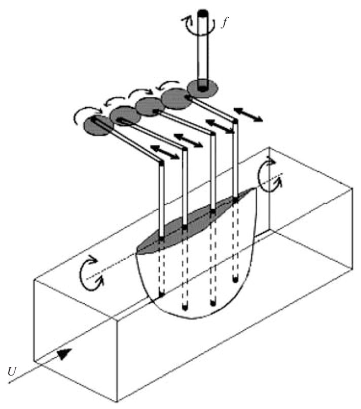
Fin actuation mechanism. A DC motor with a speed controller turns a shaft at frequency f which powers a gear train. The rotation of the gears actuates rods which impose a travelling wave along the fin through rigid spars.
The fin was placed in a recirculating water channel with a test section 0.30 m deep and 0.45 m wide. The fin chord was aligned with the free-stream direction, and the root chord was set at the free surface. A long Plexiglas plate was set at the free surface to eliminate waves. The plate was assumed to be an approximate plane of symmetry (ignoring the small differences between the boundary layers on the plate and the bottom of the channel) across which there is zero flux. Although the span of the manta ray model protruded down to 70 % of the depth of the water channel, no particular wall effects were observed.
The kinematics of the fin motion are established by the motion of the aluminium spars. A gear train, driven by a DC motor, rotates at a prescribed speed. A push rod connects each gear to its spar, such that the rotation of the gear produces a nearly sinusoidal rotation of the spar about a pivot point located at the free surface, as illustrated in figure 2. By setting a phase differential between each spar, a wave travels along the fin chord. Its wavelength is determined by the relative position of the gears of the gear train. Because each spar is rigid, the amplitude of the body motion increases with spanwise distance from the root. Although the number of spars is small, the plastic stretches between each spar and the body shape remains reasonably smooth (for details, see Clark 2005).
To measure the thrust, the fin and its actuation mechanism were supported on two Λ-shaped air-bearing sleds to minimize friction. The air tracks were mounted on the water channel, one on each side, with four thumbscrew connections, such that the pitch and roll angle of the track could be set precisely. The force on the fin was measured using an Omega brand platform load cell with a capacity of 0.6 N. The thrust was taken to be the difference between the forces measured when the fin was actuated and when it was not. The nonlinearity of the load cell was 0.02 % of the maximum rated output. Temperature changes above or below 20 °C changed results by 0.012 % per 10 °C.
For flow visualization, the fin was equipped with 30 dye injection ports, 15 on each face. The ports were located at the midchord point, running in a line from the tip for a distance of about 75 % of the span. The ports were connected to the dye reservoir using flexible tubing of comparable stiffness and specific gravity to the PVC plastic; they did not generate any noticeable deformation of the fin surface. On one side of the fin green fluoresceine dye was injected, and on the other red/orange sulforhodamine B dye, both mixed at a concentration of 50 p.p.m. by weight. The dyes were injected into the fin boundary layers, the only source of wake vorticity. The Schmidt number of the dye is of order 103, indicating that the dye tracks the vorticity for only a relatively short time. However, despite the relatively rapid diffusion of vorticity, the dye will continue to mark the core of an initially concentrated vortex, and as Buchholz & Smits (2006) have shown, dye flow visualization is a suitable tool for constructing vortex skeletons. Note that because the flow field is unsteady, the dye follows streaklines, not streamlines. The dye was illuminated with white light from several large halogen lamps.
3. Results
3.1. Thrust measurement
Thrust measurements were made at a constant flow velocity of 0.11 m s−1, corresponding to a Reynolds number based on the mean chord of the fin of 11 400. The Strouhal number was changed by modulating the frequency of the DC motor. The phase shift was changed by varying the relative positions of the push rods on the gear train, with a constant phase differential between each spar, while keeping the fin tip deflection amplitude constant at 50 mm peak-to-peak. The phase shift φ is the difference between the first and the last actuating spar. The corresponding wavelength is given by 2πc/φ.
The Strouhal number StA was defined in terms of Ā, the displacement of the trailing edge of the fin at midspan. The coefficient of thrust was defined by where T is the time-averaged thrust on the fin, ρ is the density of the fluid, and S is the planform area.
Peaks in thrust were generated at double the frequency of flapping, indicating that the fin produces thrust on the up- and downstrokes of its motion (figure 3). The time-averaged thrust data are shown in figure 4 for values of φ between 0 and 180°. Thrust measurements were taken at least four times for each data point. The average standard deviation of the data was approximately 0.1 in CT. For Strouhal numbers less than 0.1, CT varied between −0.05 and 0.05. At these low Strouhal numbers, there were no discernible effects due to phase changes. Note that Heine’s (1992) experiments on cownose rays found that the Strouhal number for steady swimming was close to 0.092, consistent with the present measurements in that the fin generates nearly zero net thrust at comparable Strouhal numbers. A direct comparison is difficult, primarily because we study an isolated fin and the forces on the rest of the body of the animal (principally the drag on the main body) are not included in our analysis.
Figure 3.
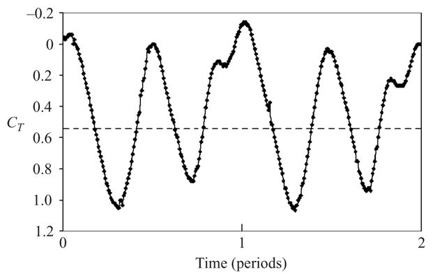
Instantaneous thrust coefficient for φ = 60° and StA = 0.2. The time-averaged value is shown by the dashed line.
Figure 4.
Coefficient of thrust as a function of Strouhal number for different travelling wave phase differentials φ.
As the Strouhal number increases the thrust coefficient increases, which is in accord with previous investigations. Strouhal numbers higher than 0.45 could not be explored using the present apparatus. For Strouhal numbers between 0.30 and 0.35, a plateau appears in the thrust data for all phase shifts, which may signal a transition in the mechanism of thrust production, as observed by Guglielmini et al. (2004) and Buchholz & Smits (2006) in the wake of a pitching plate. Flow visualizations presented below will help to shed light on this phenomenon. Also, a travelling wave phase differential in the range 60° to 90° appears to generate the maximum thrust at all Strouhal numbers.
Although the Reynolds number for these thrust data was fixed at 11 400, a Reynolds number of 17 000 was investigated for φ = 90° at Strouhal numbers of 0.15 and 0.30 by increasing the channel speed to 0.165 m s−1. The results are given in table 1. Depending on the Strouhal number, the thrust coefficient decreases by 6 % to 13 % with this 49 % increase in Reynolds number.
Table 1.
Thrust coefficient at two different Reynolds numbers.
| St | CT at Re = 11 000 | CT at Re = 17 000 |
|---|---|---|
| 0.15 | 0.16 | 0.14 |
| 0.30 | 1.82 | 1.71 |
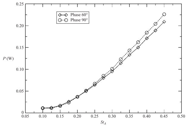
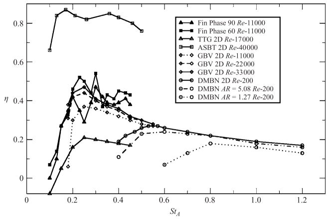
Efficiency measurements were made at two values of φ (60° and 90°) near the point of maximum thrust production. The propulsive efficiency is defined as η = T U/P. Here, P is the total power delivered to the fluid by the fin, estimated by finding the difference between the power delivered to the motor when the fin was flapping in air and when it was flapping in water, and then multiplying the result by the motor efficiency. The motor efficiency was measured using a dynamometer and ranged from 45 % to 55 % for the conditions used in these experiments. The results for P are given in figure 5, and the corresponding results for the efficiency are given in figure 6. Four to 10 separate measurements were taken to find the average values, but even so the efficiency is only accurate to ±0.05. The efficiency of the activation mechanism is low due to friction, and so the power delivered to the water by the fin represents only a small fraction of the total power needed to operate the device. Since the denominator of the efficiency formula contains the difference between two large numbers, small errors in the thrust measurements are amplified in the calculation of the efficiency, limiting the experimental accuracy.
Figure 5.
Power delivered to the water as a function of Strouhal number for φ = 60° and 90°.
Figure 6.
Efficiency as a function of Strouhal number. For the fin, St is based on Ā; for the other cases, A = Ā. Previous experimental results: TTG, Triantafyllou et al. (1993); ASBT, Anderson et al. (1998); GBV, Guglielmini et al. (2004); DMBN, Dong et al. (2005)
For φ = 90°, there is a sharp increase in efficiency above StA = 0.1, with a peak near StA = 0.25, followed by a slow decrease at higher Strouhal numbers. The results for φ = 60° are similar, and the dip near StA = 0.25 is within the range of experimental error. The data are similar to those obtained by Anderson et al. (1998) and Guglielmini et al. (2004). Low-Reynolds-number simulations by Dong et al. (2005) indicate peak efficiencies at a higher Strouhal number, an effect that is most likely due to significant viscous effects at the low Reynolds number of the simulation (100 to 400). The data fit well with the observations by Triantafyllou et al. (1993) on the characteristic Strouhal number for cruising fish, although it should be borne in mind that their Strouhal number is based on the wake width, whereas here it is based on the spanwise average deflection of the trailing edge.
The present data show a peak efficiency of around 40 %, which is higher than that measured by Triantafyllou et al. and lower than that by Anderson et al. Note that the particular gait studied by Triantafyllou et al. (1993) was not optimized in any way. In contrast, Anderson et al. used high-aspect-ratio foils with optimized gaits. The high-aspect-ratio results from Guglielmini et al. (2004) are lower than Anderson et al.’s, probably because of viscous effects. Guglielmini et al.’s results agree well with the fin efficiency data presented here at higher Reynolds numbers where higher values are expected, but the fin has a lower aspect ratio where lower efficiencies are expected, as shown by the data by Dong et al. (see figure 6).
3.2. Wake topology
All flow visualizations were performed with a free-stream velocity of 6 mm s−1, corresponding to a Reynolds number of 680 based on the mean chord of the foil. At this low Reynolds number the wake structure could be readily interpreted, but viscous forces are expected to be more important than at the Reynolds number where the thrust measurements were made (11 000). These differences could not be quantified, but the qualitative impression derived from attempts at flow visualization at higher Reynolds numbers suggested that increasing the Reynolds number affects the spacing and aspect ratio of the observed vortex loops but not the underlying vortex structure. All flow visualizations were conducted with φ = 90°, corresponding closely to the phase difference where maximum thrust was produced. Most of the visualizations were performed at StA = 0.15, where the wake structure is relatively simple, and the thrust coefficient lies below the plateau region seen in figure 4.
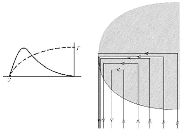
To help interpret the flow visualizations, it is useful first to consider the instantaneous circulation distribution on the fin, as shown in figure 7, together with the corresponding shed vorticity. The figure corresponds to a point in the flapping cycle where the tip of the fin is moving out of the page, and a vortex is about to be shed from the trailing edge. The model distribution is based on the assumptions of quasi-steady, two-dimensional flow. Because the root of the fin is fixed and symmetric, no circulation is produced in this region. Also, no circulation is produced at the tip because the area is zero. Therefore, a maximum in the circulation distribution must appear in the region of the fin near the outer part of the span, as shown in the figure. This circulation alternates in sign as the fin moves up and down about its rest position.
Figure 7.
Solid line: proposed instantaneous spanwise circulation distribution on the fin at one value of φ, averaged over the chord. Dashed line: circulation distribution on a rigid elliptic wing at a fixed angle of attack. The strength of the shed vorticity corresponds qualitatively to the vortex line spacing shown on the right.
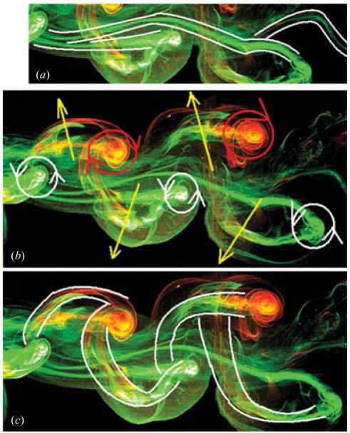
For the visualization shown in figure 8, the fin is located just to the left of the image and the view is from above (looking along the span from root to tip). Components of this wake structure at three spanwise positions are highlighted in figure 9.
Figure 8.

Flow visualization in the near wake of the fin at φ = 90° and StA = 0.15. The green dye was injected from one side of the fin, the red dye from the other side. Flow is from left to right. View is from above, looking along the span.
Figure 9.
Features of the wake shown in figure 8. (a) Long vortex ‘tails’ found in the region of the wake near the fin root. (b) Vortex cores of alternating sign found in the wake in the region near the mid-span. The arrows show the direction of the induced velocities. (c) Connections between vortex cores found in the region of the wake near the fin tip.
Figure 9(a) highlights the region of the wake near the fin root, showing long vortex ‘tails’ that have weak circulation since the lift generated near the fin root is almost zero. These vortices meander as they respond to the induced velocity field of the stronger vortices formed farther along the span. The wake of the near-root region of the fin exhibited this behaviour at all Strouhal numbers investigated.
Figure 9(b) identifies several vortex pairs of alternating sign. The vortex cores have relatively high circulation because this part of the wake is generated just below the mid-span, near where the circulation on the fin reaches its maximum. The vorticity associated with the vortex cores is oriented mostly in the spanwise direction; the streamwise vorticity generated by the finite-aspect-ratio fin is isolated closer to its tip. The directions of the induced velocities suggest that the wake of the fin may have a small streamwise momentum deficit compared to the free-stream flow, producing some drag. However, the flow field is highly three-dimensional and evaluation of a planar component of the flow does not describe the bulk properties of the wake very well. The thrust measurements demonstrated that this condition was close to an equilibrum condition where the fin produces a small time-averaged thrust, with a thrust coefficient of approximately 0.1.
Figure 9(c) highlights components of the wake which are generated near the tip, where the streamwise vorticity is concentrated to form a structure similar to a wing-tip vortex, except that the strength of the vortex is continually changing along its length, reversing sign every half-cycle. These parts of the wake near the tip appear to form connections between the previously discussed spanwise vortex cores, and their induced velocities cause the observed spreading of the wake.
The vortex interaction near the tip of the fin is shown in more detail in figure 10. As the green vortex at the left of the image is shed, it entrains the tail of the streamwise component red/green vortex formed in the previous cycle. The upstream vortex has greater circulation than the streamwise vortex farther downstream, and the weaker downstream vortex is pulled around the upstream vortex, forming a horseshoe-like structure. One leg of the horseshoe remains connected to the red/green streamwise vortex, and the other leg winds around the green vortex, proceeding to the tip of the fin, thereby satisfying the no slip condition.
Figure 10.
The interaction of two vortices at StA = 0.15 near the tip of the fin. Flow is from left to right. View is from the side, looking at the fin in planform. The trailing edge of the fin is visible in the upper left hand corner. Image (b) highlights the horseshoe vortex structure seen without highlights in (a).
This mechanism of vortex interaction was also observed by Buchholz & Smits (2006) for a rigid pitching panel of aspect ratio 0.54 at St = 0.22. They described the connections between spanwise vortex cores, where each vortex could be traced back to the trailing edge of the panel through a series of interactions with vortices of the same or opposite sign. Their panel was rectangular, so that the displacement did not vary along its trailing edge. In contrast, the fin trailing edge displacement and the length of the chord vary in the spanwise direction. Nevertheless, the vortex interaction generates a spanwise compression of the wake, similar to that seen by Buchholz & Smits (2006), and the other studies on finite-aspect-ratio bodies by Guglielmini et al. (2004) and Dong et al. (2005), providing some support for the broad applicability of the vortex interaction mechanisms described by Buchholz & Smits.
Based on the flow visualization evidence, a vortex model is proposed for the wake at a Strouhal number of 0.15. Figure 11 illustrates the suggested vortex skeleton at a point in the flapping cycle where the tip of the fin is moving out of the page, and a vortex is about to be shed from the trailing edge, that is, it is at the same point in the cycle used to draw the circulation distribution in figure 7. The thickness of each vortex line is drawn to correspond qualitatively to the strength of its circulation, and because the flow is unsteady, the circulation varies along the length of a given vortex. In this model, parts of the vortex formed near the tip wind around parts of the vortex formed near the midspan. Each vortex is wound around successive upstream vortices, terminating at the body with nearly zero circulation, or merging with an interacting vortex by viscous diffusion. The interactions among vortices correspond to the distribution of circulation proposed in figure 7. At this low Strouhal number, the relatively fast convection of the flow generates vortex interactions in which the most upstream vortex always dominates the interaction. At the point where the circulation of the upstream vortex is a maximum, the component of the downstream vortex formed near the tip is entrained, where the circulation is comparatively weak.
Figure 11.
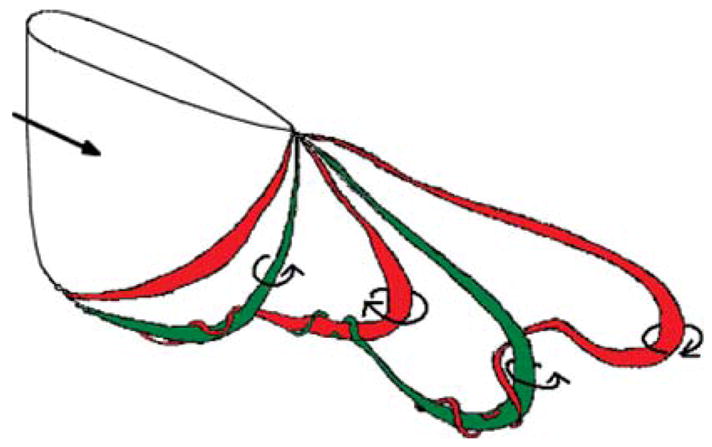
The vortex model proposed for StA = 0.15 at the time when the trailing edge vortex is about to shed. The colors indicate the sign of the circulation, also illustrated by the arrows.
The vortex interaction mechanisms are more complex at higher Strouhal numbers because vortices interact in regions where they are of more equal strength. Figure 12 illustrates the vortex structure at a Strouhal number of 0.25, where the highest efficiency of propulsion is found. The underlying structure is highlighted in figure 12(b). By an interaction mechanism that is similar to that seen at StA = 0.15, the vortices become much more twisted than at that Strouhal number. This twisted structure is quickly sheared apart by its self-induced velocity field, as well as the velocity field induced by the red/orange vortex figure 12(a), such that a portion of the green vortex moves both in and out of the page. The two vortices ‘split’ and move in opposite directions, forming a V-shaped pattern (as seen from above, looking along the span) in the wake in which both red and green dye are found on each side of the wake and little dye appears in the central part of the wake. This vortex structure may be similar to the 2P structure described by Williamson & Roshko (1988), but its inherent three-dimensionality makes it considerably more complex.
Figure 12.
Flow visualizatons at StA = 0.25 near the tip of the fin. Flow is from left to right. View is from the side, looking at the fin in planform. The trailing edge of the fin is visible in the upper left hand corner. Image (b) highlights the twisted vortex vortex structure seen without highlights in (a).
At Strouhal numbers above 0.25, the wake undergoes a transition to a new kind of structure, consistent with the observations by Buchholz & Smits (2006), Guglielmini et al. (2004), and Dong et al. (2005) for rigid plates. Although a single red/orange vortex is generated initially, it is quickly sheared apart and pushed both above and below the planform of the fin. All segregation of dye colours is eliminated, as green and red dye each are found in abundance on both sides of the wake. Although the transition to this new structure is not sudden, segregation of the dye colours begins to break down above StA = 0.25. Figure 13 illustrates the dramatic changes that occur in the wake structure as the Strouhal number increases.
Figure 13.
Flow visualizatons in the near wake looking from above, along the span. Flow is from left to right. (a) StA = 0.075. (b) StA = 0.30.
4. Discussion and conclusion
Experiments were performed on a flexible fin model that mimics some features of the unsteady thrust production seen in rays and skates. The fin had an elliptic planform and a symmetrical airfoil cross-section, and it was actuated using rigid spars to produce a travelling wave undulation. A Strouhal number based on the displacement of the trailing edge midway along the span was found useful, as it may be for other studies of flexible fins. An optimal travelling wave phase differential of 60° to 90° was identified, consistent with observations of mobuliform motion (Rosenberger 2001). A plateau in the thrust production occurred at a Strouhal number near 0.30, close to the value of 0.25 where the peak efficiency was found. The Strouhal number at zero net thrust was similar to the Strouhal number demonstrated by the cownose ray swimming at a constant velocity, although comparisons with animal studies can only be made obliquely since the present study is concerned with an isolated fin, and the effects of the central body were not included. Furthermore, the fin was not allowed to accelerate, as it would do under a non-zero thrust in the absence of a tether, and so does not mimic a freely swimming entity.
The wake structures were interpreted using a model of the circulation distribution on the fin that accounts for the spanwise variation in the displacement of the trailing edge. At low Strouhal numbers (≤ 0.15), vortices of opposite sign interact such that the most upstream vortex dominates the interaction. Near the root, there is minimal vortex interaction because little circulation is generated in this region. At higher Strouhal numbers, in regions away from the root, a greater degree of vortex interaction generates spanwise compression of the wake, which makes the wake spread above and below the planform. This is consistent with previous studies of rigid finite-aspect-ratio propulsors. A vortex model is presented for StA = 0.15.
The thrust generated by the fin and the structure of the wake are clearly connected, because the pressure forces and viscous forces which act on the body to produce thrust give rise to the vorticity field in the wake. There is some ambiguity in making a direct connection between the instantaneous thrust and the wake structure because a higher Reynolds number was needed for accurate thrust measurements compared to the value of the Reynolds number used for the flow visualization (11 000 compared with 680). It appears, however, that the peaks in the momentum production occur almost at the same time as the peaks in the excursion of the fin trailing edge, at least at low Strouhal numbers. As the Strouhal number increases, a transition in the wake structure was found to occur at about the same Strouhal number where the thrust coefficient displayed a plateau and the efficiency reached a maximum (ST ≈ 0.3). The wake appears to split, and it was no longer clear how the peak excursion of the motion and the peak in the thrust were connected.
For the Strouhal numbers studied here, strong similarities exist among the wake of the flexible fin model, and the wakes observed by Guglielmini et al. (2004), Dong et al. (2005) and Buchholz & Smits (2005) for rigid plates. The peak efficiency generated by the finite-aspect-ratio fin is 54 %, which is less than the peak efficiency of 87 % generated by the high-aspect-ratio foil (Anderson et al. 1998). However, further optimization of the shape and kinematics of the fin, perhaps by investigating alternative planforms and including spanwise curvature, may increase the efficiency.
James Buchholz is gratefully acknowledged for his assistance and advice, and our thanks go to Professor Frank Fish for allowing us to use his manta ray photographs and freely sharing his advice. This work was supported by NIH under the CRCNS Program.
References
- Anderson JM, Streitlien K, Barrett DS, Triantafyllou MS. Oscillating foils of high propulsive efficiency. J Fluid Mech. 1998;360:41–72. [Google Scholar]
- Bannasch R. Hydrodynamics of penguins – an experimental approach. In: Dann P, Norman I, Reilly P, editors. The Penguins: Ecology and Management. Surrey Beatty and Sons; Norton, NSW, Australia: 1995. pp. 141–176. [Google Scholar]
- Buchholz JHJ, Smits AJ. On the evolution of the wake structure produced by a low-aspect-ratio pitching panel. J Fluid Mech. 2006;546:433–443. doi: 10.1017/S0022112005006865. [DOI] [PMC free article] [PubMed] [Google Scholar]
- Clark RP. MSE thesis. Princeton University; 2005. Hydrodynamics of an experimental model of a manta ray pectoral fin. [Google Scholar]
- Compagno LJV. Systematics and body form. In: Hamlet WC, editor. Sharks, Skates and Rays: The Biology of Elasmobranch Fishes. Johns Hopkins University Press; 1999. [Google Scholar]
- Dong H, Mittal R, Bozkurttas M, Najjar F. Wake structure and performance of finite aspect ratio flapping foils. AIAA Paper. 2005:2005–0081. [Google Scholar]
- von Ellenrieder KD, Parker K, Soria J. Flow structures behind a heaving and pitching finite-span wing. J Fluid Mech. 2003;490:129–138. [Google Scholar]
- Guglielmini L, Blondeaux P, Vittori G. A simple model of propulsive oscillating foils. Ocean Engng. 2004;31:883–899. [Google Scholar]
- Heine C. PhD thesis. Duke University; 1992. Mechanics of flapping fin locomotion in the cownose ray, rhinoptera bonasus (elasmobranchii: Myliobatidae) [Google Scholar]
- Klausewitz W. Natur-Museum und Forschungsinstitut Senckenberg. 1963. Der lokomotionsmodus der flugelrochen (myliobatoidei) pp. 111–117. [Google Scholar]
- Lauder GV, Drucker EG. Morphology and experimental hydrodynamics of fish fin control surfaces. IEEE J Ocean Engng. 2004;29:556–571. [Google Scholar]
- Lighthill MJ. Note on the swimming of slender fish. J Fluid Mech. 1960;9:305–317. [Google Scholar]
- McHenry MJ, Pell CA, Long JH. Mechanical control of swimming speed: Stiffness and axial wave form in undulating fish models. J Expl Biol. 1995;198:2293–2305. doi: 10.1242/jeb.198.11.2293. [DOI] [PubMed] [Google Scholar]
- Rayner JMV. A vortex theory of animal flight. Part 1. The vortex wake of a hovering animal. J Fluid Mech. 1979a;91:697–730. [Google Scholar]
- Rayner JMV. A vortex theory of animal flight. Part 2. The forward flight of birds. J Fluid Mech. 1979b;91:731–763. [Google Scholar]
- Rosenberger L. Pectoral fin locomotion in batoid fishes: Undulation versus oscillation. J Expl Biol. 2001;204:379–394. doi: 10.1242/jeb.204.2.379. [DOI] [PubMed] [Google Scholar]
- Schaefer J, Summers A. Batoid wing skeletal structure: Novel morhphologies, mechanical implications, and phylogenetic patterns. J Morphology. 2005;264:298–313. doi: 10.1002/jmor.10331. [DOI] [PubMed] [Google Scholar]
- Triantafyllou MS, Triantafyllou GS. An efficient swimming machine. Sci Am. 1995;272(3):64–70. [Google Scholar]
- Triantafyllou MS, Triantafyllou GS, Gopalkrishnan R. Wake mechanics for thrust generation in oscillating foils. Phys Fluids A. 1991;3:2835–2837. [Google Scholar]
- Triantafyllou GS, Triantafyllou MS, Grosenbaugh MA. Optimal thrust development in oscillating foils with application to fish propulsion. J Fluid Struct. 1993;7:205–224. [Google Scholar]
- Williamson CHK, Roshko A. Vortex formation in the wake of an oscillating cylinder. J Fluid Struct. 1988;2:355–381. [Google Scholar]


