Abstract
This paper describes an algorithm to extract adaptive and quality quadrilateral/hexahedral meshes directly from volumetric data. First, a bottom-up surface topology preserving octree-based algorithm is applied to select a starting octree level. Then the dual contouring method is used to extract a preliminary uniform quad/hex mesh, which is decomposed into finer quads/hexes adaptively without introducing any hanging nodes. The positions of all boundary vertices are recalculated to approximate the boundary surface more accurately. Mesh adaptivity can be controlled by a feature sensitive error function, the regions that users are interested in, or finite element calculation results. Finally, a relaxation based technique is deployed to improve mesh quality. Several demonstration examples are provided from a wide variety of application domains. Some extracted meshes have been extensively used in finite element simulations.
Keywords: quadrilateral/hexahedral mesh, topology preservation, mesh adaptivity, mesh quality
1 Introduction
Unstructured quadrilateral/hexahedral mesh generation attracts many researchers' interest because of its important applications in finite element simulations. However, it still remains a challenging and open problem to generate adaptive and quality quad/hex meshes directly from volumetric data, such as Computed Tomography (CT), Magnetic Resonance Imaging (MRI) and Signed Distance Function (SDF) data.
The volumetric data V is a sequence of sampled functional values on rectilinear grids, and can be written as V = {F(i,j,k)|i,j,k are indices in x,y,z coordinates in a rectilinear grid}. An isosurface or a level set corresponding to the isovalue α is defined as SF(α) = {(x,y,z)|F(x,y,z) = α}, and an interval volume between two isosurfaces SF(α1), SF(α2) is defined as IF(α1,α2) = {(x,y,z)|α1 ≤ F(x,y,z) ≤ α2}. In this paper, we present an approach to extract adaptive and quality quadrilateral meshes for an isosurface SF(α) with correct topology, and hexahedral meshes for an interval volume IF(α1, α2) with isosurfaces as boundaries. In certain finite element simulations, both interior and exterior hexahedral meshes are required, for example, the interior mesh of the volume inside the solvent accessibility surface of the biomolecule mouse acetylcholinesterase (mAChE) [31] [30], and the exterior mesh between the solvent accessibility surface and an outer bounding sphere. Since the most important part in the geometric structure of mAChE is the cavity, we need to generate finer mesh for it (Figure 1). Our approach can also generate adaptive and quality interior and exterior hexahedral meshes.
Fig. 1.

Adaptive quadrilateral and hexahedral meshes of a biomolecule mAChE. (a) - the quadrilateral mesh of the molecular surface; (b) - the wireframe of the adaptive quadrilateral mesh of the molecular surface; (c) - the adaptive hexahedral mesh of the interior volume; (d) - the adaptive hexahedral mesh of the exterior volume between the molecular surface and an outer sphere. Finer meshes are generated in the region of the cavity, while coarser meshes are kept in other areas. The cavity is shown in the red boxes.
The main steps to extract adaptive and quality quadrilateral and hexahedral meshes from volumetric data are as follows:
The selection of a starting octree level for uniform mesh generation with correct topology.
Crack-free and adaptive quad/hex meshing without any hanging nodes.
Quality improvement.
In order to generate uniform quadrilateral and hexahedral meshes with correct topology, we select a suitable starting octree level using a bottom-up surface topology preserving octree-based algorithm. An approach provided in [15] is used to check whether a fine isosurface is topologically equivalent to a coarse one or not. Generally correct topology is guaranteed in the uniform mesh.
The dual contouring method [15] proposes an algorithm to extract a uniform quadrilateral mesh for an isosurface by analyzing each sign change edge, whose two ending points lie in different sides of the isosurface. In the octree-based data structure, each sign change edge is shared by four octree leaves, and one minimizer point is obtained for each leaf cell by minimizing a predefined quadratic error function (QEF) [14]. The QEF is defined as follows:
| (1) |
where pi, ni represent the position and unit normal vectors of the intersection point respectively. Figure 2 shows one 2D example. The four minimizer points construct a quad, and the union of all the generated quads provides an approximation to this isosurface.
Fig. 2.
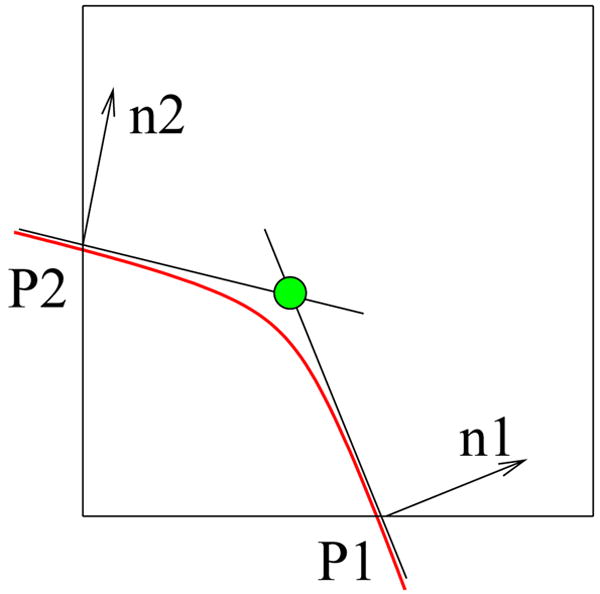
The quadratic error function (QEF) and the minimizer point in 2D. The red curve is an isocontour, and the green point is the minimizer point calculated in Equation 1. (p1, n1) and (p2, n2) represent the position and unit normal vectors of the two intersection points.
Starting from a uniform quadrilateral mesh, we use templates to refine each quad adaptively. The position of each vertex is recalculated by moving it toward the isosurface along its normal direction, which is represented by trilinear interpolation functions within octree leaf cells. The dual contouring isosurface extraction method has been extended to uniform hexahedral mesh generation [38] [39]. In this paper, predefined three dimensional templates are used to generate adaptive hexahedral meshes.
The mesh adaptivity can be controlled according to various requirements by a feature sensitive error function [38] [39], areas that users are interested in, or results from finite element calculations. Users can also design an error function to control the mesh adaptivity according to their specific requirements.
Generally, the extracted quadrilateral and hexahedral meshes can not be used for finite element calculations directly since some elements have poor quality. We choose corresponding metrics to measure the quality of quadrilateral and hexahedral meshes respectively, and deploy a relaxation based technique to improve mesh quality. Several of our generated meshes have been used in finite element simulations.
The remainder of this paper is organized as follows: Section 2 reviews the related work on quadrilateral/hexahedral mesh generation; Section 3 describes how to choose the starting octree level; Sections 4 and 5 explain the detailed algorithm for extracting adaptive quadrilateral and hexahedral meshes; Section 6 talks about three ways to control the mesh adaptivity; Section 7 discusses the mesh quality improvement; Section 8 shows some results and applications; the final section presents our conclusions.
2 Previous Work
As a structured method, quad/hex mapped meshing [9] generates the most desirable meshes if opposite edges/faces of the domain to be meshed have equal numbers of divisions or the same surface mesh. However, it is always difficult to decompose an arbitrary geometric configuration into mapped meshable regions. In the CUBIT project [1] at Sandia National Labs, a lot of research has been done to automatically recognize features and decompose geometry into mapped meshable areas or volumes.
As reviewed in [23] [35], there are indirect and direct methods for unstructured quad/hex mesh generation. The indirect method is to generate triangular/tetrahedral meshes first, then convert them into quads/hexes. The direct method is to generate quads/hexes directly without first going through triangular/tetrahedral meshing.
Unstructured Quad Mesh Generation
The indirect method is to convert triangles into quads by dividing a triangle into three quads, or combining adjacent pairs of triangles to form quads [20].
There are three main categories for unstructured direct quad mesh generation: quad meshing by decomposition, advancing front quad meshing and isosurface extraction. The decomposition technique divides the domain into simpler regions which can be resolved by templates [2] [33]. The second category is to utilize a moving front method for direct placement of nodes and elements. Starting with an initial placement of nodes on the boundary, Zhu et al. [40] formed individual elements by projecting edges towards the interior. As a part of CUBIT [1], the paving algorithm places elements starting from the boundary and works in [5]. Different from the decomposition and the advancing front techniques, the dual contouring method [15] extracts uniform quadrilateral meshes from volumetric data to approximate isosurfaces which can be an arbitrary geometry.
Unstructured Hex Mesh Generation
Eppstein [10] started from a tetrahedral mesh to decompose each tetrahedron into four hexahedra. Although this method avoids many difficulties, it rapidly increases the number of elements and tends to introduce poorly shaped elements.
There are five distinct methods for unstructured direct all-hex mesh generation: grid-based, medial surface, plastering, whisker weaving and isosurface extraction. The grid-based approach generates a fitted 3D grid of hex elements on the interior of the volume, and hex elements are added at the boundaries to fill gaps [26] [28] [29]. The grid-based method is robust, but tends to generate poor quality elements at the boundaries. Medial surface methods decompose the volume into mapmeshable regions, and fill the volume with hex elements using templates [24] [25]. Plastering places elements on boundaries first and advances towards the center of the volume [6] [4]. Whisker weaving first constructs the spatial twist continuum (STC) or dual of the hex mesh, then the hex elements can be fitted into the volume using the STC as a guide [34]. Medial surface methods, plastering and whisker weaving have successfully generated hex meshes for some geometry, but have not been proven to be robust and reliable for an arbitrary geometric domain. Zhang et al. [38] [39] extended the dual contouring isosurface extraction method [15] to uniform hexahedral mesh generation. This method is robust and reliable for an arbitrary geometry, but adaptive meshes are preferable and mesh quality needs to be improved.
Quality Improvement
As the simplest and most straight forward method, Laplacian smoothing relocates the vertex position at the average of the nodes connecting to it [11]. There are a variety of other smoothing techniques based on a weighted average of the surrounding nodes and elements. The averaging method may invert or degrade the local quality, but it is simple to implement and in wide use. Instead of relocating vertices based on a heuristic algorithm, people utilized an optimization technique to improve mesh quality. The optimization algorithm measures the quality of the surrounding elements to a node and attempts to optimize it. The algorithm is similar to a minimax technique used to solve circuit design problems [8]. Optimization-based smoothing yields better results but it is more expensive than Laplacian smoothing. Some papers [7] [12] [13] recommended a combined Laplacian/optimization-based approach.
Staten et al. [32] [16] proposed algorithms to improve node valence for quadrilateral meshes. One special case of cleanup in hexahedral meshes for the whisker weaving algorithm is presented in [21]. Schneiders [27] proposed algorithms and a series of templates for quad/hex element decomposition. A recursive subdivision algorithm was proposed for the refinement of hex meshes [3].
3 Starting Octree Level Selection
There are three main steps in our adaptive and quality quadrilateral and hexahedral mesh extraction from volumetric data. First, we need to choose a suitable starting octree level to generate the uniform mesh with correct topology. Then pre-defined templates are used to refine the uniform mesh adaptively. The positions of all boundary vertices are recalculated, and the mesh adaptivity can be controlled by an error function designed in multiple ways. Finally, the relaxation based technique is used to improve mesh quality.
The bottom-up surface topology preserving octree-based algorithm is used to select a starting octree level. Suppose the volume data has the dimension of (2n + 1)3, so the deepest octree level is n. For an isosurface, we first compare the surface topology at Level n and Level (n − 1). If the surface topology is equivalent, then we continue comparing the surface topology at Level (n − 1) and Level (n − 2) until we find the surface topology at two neighboring levels, e.g. Level i and Level (i − 1) (i = n,…,1), is different from each other. Then we will select i as the starting octree level.
We assign a sign to each grid point in the volumetric data. If the function value at a grid point is greater than the isovalue, then the sign is 1, otherwise it is 0. An approach is described in [15] to check whether a fine isocontour is topologically equivalent to a coarse one or not. The fine and coarse isocontour is topologically equivalent with each other if and only if the sign of the middle vertex of a coarse edge/face/cube is the same as the sign of at least one vertex of the edge/face/cube which contains the middle vertex. Generally we guarantee the correct topology for the boundary surfaces by choosing a suitable starting octree level, and correct topology will be preserved in the process of adaptive mesh refinement.
4 Quad Isosurface Extraction
Finite element calculations sometimes require quadrilateral meshes instead of triangular meshes. It is more challenging to generate quadrilateral meshes since not every polygon can be decomposed into quads directly. The uniform quadrilateral mesh extraction algorithm is simpler [15], but adaptive meshes are preferable over uniform ones. There are two main problems in adaptive quadrilateral mesh extraction.
How to decompose a quad into finer quads.
How to calculate the positions of vertices.
4.1 Mesh Decomposition
Indirect Method
In the dual contouring isosurface extraction method [15], an error function is defined to control where we should generate fine meshes, and where we should keep coarse ones. In the adaptive octree data structure, either a sign change edge is shared by three cells resulting in a triangle, or it is shared by four cells and a quad is generated. Therefore, the isosurface is represented by a union of quads and triangles. In order to obtain an all-quad mesh, the indirect method splits each quad into four quads and each triangle into three quads by inserting points at the middle of edges and at the center of the element as shown in Figure 3. The idea of the indirect method is simple and easy to implement, but the number of elements increases by a factor of 2 to 3 over the original mesh.
Fig. 3.
The templates to decompose a quad or a triangle into quads. Red points are newly inserted at the middle of edges or the element center. (a) - a quad before splitting; (b) - a triangle before splitting; (c) - a quad is split into four quads; (d) - a triangle is split into three quads.
Direct Method
At the selected starting octree level, the dual contouring isosurface extraction method [15] generates uniform quadrilateral meshes by analyzing each sign change edge which is shared by four leaf cells. Adaptive quadrilateral meshes can be obtained from the uniform mesh by using some templates. There are multiple ways to define templates for adaptive quadrilateral mesh construction, therefore criteria needs to be set to evaluate them in order to generate meshes with good quality. Here we define some requirements for templates:
All resulting elements are quads.
No hanging nodes exist.
The resulting mesh approximates the object surface accurately.
The resulting elements have good aspect ratio.
The resulting mesh introduces a small number of new elements and vertices.
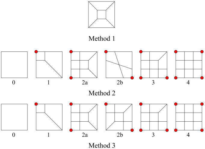
Figure 4 shows three methods to define templates for adaptive quadrilateral mesh generation starting from a uniform mesh with correct topology. In the uniform case, each sign change edge is shared by four cells and four minimizer points are obtained to construct a quad. In Method 1, if the maximum error function value (for example, the feature sensitive error function defined in [38] [39]) of the four cells is greater than a threshold ε, then the four octree cells containing the sign change edge should be subdivided, and the quad generated from this edge should be refined. This method does not consider its neighboring information, each quad is refined independently. If a quad needs to be refined, then the resulting mesh has 5 elements and 4 newly inserted vertices. In Method 2 [29] and 3, various decomposition methods are chosen according to the cell which generates a quad node and also needs to be refined. Method 2 and 3 are only different in Case (2b), Method 2 generates less elements and vertices, but the quad quality is worse than in Method 3.
Fig. 4.
Three different methods to define templates for adaptive quadrilateral isosurface extraction. In Method 1, the quad needs to be refined; In Method 2 and 3, octree leaf cells generating red minimizer points need to be refined.
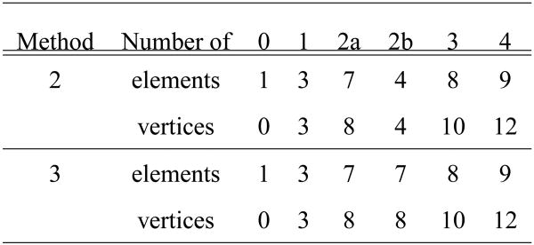
We can use the above five template requirements to compare the three methods in Figure 4. It is obvious that all the three methods only generate quad elements, and no hanging nodes are introduced. Compared with Method 1, Methods 2 and 3 insert extra nodes on the quad edges as well as inside the quad, so they can approximate the surface more accurately. Comparing the worst aspect ratio of the resulting quad elements in Method 2 and 3, we can see that Method 3 generates quads with better quality. The number of elements and the number of newly inserted vertices for each template are listed in Figure 5. Method 3 is preferable by balancing the five criteria.
Fig. 5.
The number of elements and the number of newly inserted vertices for templates in Methods 2 and 3 shown in Figure 4.
4.2 Vertex Position Calculation
In the process of mesh refinement, new vertices are inserted according to the pre-defined templates. The next step is to update the positions of existing vertices and calculate the positions of newly inserted vertices.
In Figure 6, we assume that the leaf cell can be divided into four subcells in the finest resolution level, therefore the real isosurface (the red curve) is represented by a union of three trilinear interpolation functions within the subcells. For each existing minimizer point, first we find the octree leaf cell containing it in the current resolution level, then move it toward the isosurface within this leaf cell along its normal direction. The intersection point is more accurate to represent this boundary vertex than the minimizer point. If the calculated intersection point lies outside this cell unfortunately because of bad normal vectors, we will still keep old position and normal vectors.
Fig. 6.
The calculation of vertex positions. (a) - one leaf cell; (b) - the leaf cell is subdivided into four subcells, and three minimizer points are obtained; (c) - the three minimizer points are moved to the isocontour along their normal directions. The red curve is the real isocontour. The green circle point represents an existing minimizer point of this leaf cell, and blue circle points are two newly inserted vertices. The arrows are their normal vectors, the green and blue box points are the resulting vertices.
For those newly inserted vertices, we first calculate their position and normal vectors by linear interpolation of the four vertices of the original quad. Then we will move them toward the isosurfaces in the same way as we update the positions of existing vertices.
Figure 7 shows adaptive quadrilateral meshes of the human head generated from two direct methods, Method 1 and Method 3 shown in Figure 4. It is obvious that the original uniform mesh is refined adaptively, and the new vertex positions are closer to the isosurface. Method 1 generates a bad nose, and Method 3 approximates the isosurface more accurately than Method 1 because it introduces extra vertices on the refined edges of each original quad. The mesh adaptivity is controlled by a feature sensitive error function [38] [39], which is sensitive to facial features such as the nose, the eyes, the mouth and the ears.
Fig. 7.
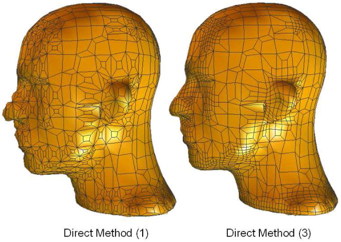
Adaptive quad meshes generated from two direct methods. A feature sensitive error function [38] [39] is chosen for mesh adaptivity, the isovalue α = 0, the error tolerance ε = 0.4. Method 1 generates a poor nose, and Method 3 generates a better result.
5 Hexahedral Mesh Extraction
The dual contouring method [15] has been extended to uniform hexahedral mesh generation by analyzing each interior vertex (a grid point inside the interval volume) shared by eight different cells, which are either boundary cells or interior cells [38] [39]. A minimizer point is calculated for each boundary cell, and the cell center is set as the minimizer point for each interior cell. Those eight minimizer points construct a hexahedron. In this section, we will focus on adaptive hexahedral mesh generation.
5.1 2D Mesh Decomposition
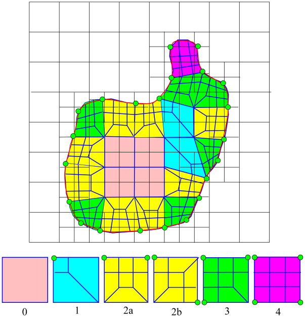
In 2D, the uniform quadrilateral mesh can be constructed by analyzing each interior grid point, which is shared by four cells. One minimizer point is calculated for each cell, therefore four minimizer points are obtained and they construct a quad. All the templates defined in Figure 4 can be used here for adaptive 2D mesh generation. Figure 8 shows an example of adaptive quadrilateral mesh extraction using Method 3. When we analyze each cell to calculate the minimizer point, we compare the feature sensitive error function of this cell with a threshold ε. If the error function value of a cell is greater than ε, then this cell needs to be subdivided. An interior grid point is shared by four cells, therefore there are a total of 24 = 16 configurations. Due to the symmetry, there are six basic templates for the quad refinement. A uniform quadrilateral mesh can be refined adaptively by using those templates.
Fig. 8.
Top row - an example of adaptive quad mesh generation in 2D. Each green point represents a minimizer point of a cell to be refined, and the red curve represents the real isocontour. Bottom row - the decomposition templates of Method 3 shown in Figure 4.
5.2 3D Mesh Decomposition
Indirect Method
Adaptive and quality tetrahedral meshes have been generated from volumetric imaging data [38] [39], therefore we can obtain hexahedral meshes by decomposing each tetrahedron into four hexahedra.
Direct Method
Not all the direct methods for adaptive 2D mesh generation shown in Figure 4 can be extended to 3D. There are two main methods for adaptive hexahedral mesh generation, one is extended from the first 2D direct method and the other one is derived from part of the third 2D direct method.
Extended from the first 2D direct method in Figure 4, Method 1 refines each hexahedron independently as shown in Figure 9. It first splits each hexahedron into seven hexahedra by inserting one small hex in its center, and each face of the original hex is contained in a hex independently. If one face needs to be refined, then the hex containing it will be refined as shown in the right picture of Figure 9. If there are i (i = 1,…,6) faces that need to be refined for a hexahedron, then the resulting mesh has (6i + (6 − i) + 1 = 5i + 7) elements and 8(i + 1) newly inserted vertices.
Fig. 9.
Adaptive hexahedral mesh decomposition (Method 1). Left - a 2D example; Middle - a small hexahedron is inserted; Right - the top face of the original hexahedron needs to be refined, 6 hex and 8 extra vertices are generated.
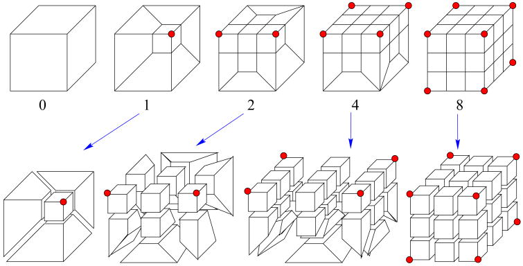
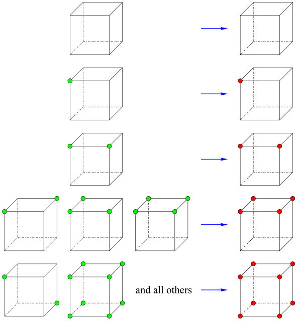
Method 2 is derived from part of the third 2D direct method shown in Figure 4. In the process of refinement, this method considers whether the error function value of each cell is greater than a threshold ε or not. One hexahedron has a total of eight vertices, so there are (28 = 256) configurations. Due to symmetry, there are only 22 unique templates [36], but only five templates are useful out of them because not all the templates can be decomposed into hexahedra. Figure 10 shows the five templates for adaptive hexahedral decomposition together with a detailed view [29], which are much more complicated than the templates for 2D quadrilateral decomposition. Figure 11 lists the number of elements and the number of newly inserted vertices for each template.
Fig. 10.
Templates of adaptive hexahedral mesh decomposition (Method 2) according to the cells to be refined from which red minimizer points are generated. The bottom row shows the detailed decomposition format.
Fig. 11.
The element number and the newly inserted vertex number of Method 2 within refined hexahedra shown in Figure 10.
We set a sign for each leaf cell at the uniform starting octree level indicating if this cell needs to be refined or not. For each leaf cell, the feature sensitive error function is calculated and compared with a threshold ε. If the function value is greater than ε, then the sign is set to be 1, otherwise it is 0. For each hexahedron extracted from the uniform level, we check if it belongs to one of the templates shown in Figure 10. If not, we need to convert it by looking up the table shown in Figure 12. We keep updating the sign for each leaf cell until no sign changes, at this time all the generated hexahedra in the uniform level are in the format of the five templates shown in Figure 10, then we can construct an adaptive hexahedral mesh using the corresponding templates.
Fig. 12.
The Look-Up table for converting an arbitrary configuration to one of the five templates in Figure 10. Each green node represents the cell from which the minimizer point is generated needs to be refined. The sign of the cell generating a red node is 1, otherwise the sign is 0.
Each hexahedron is constructed by eight minimizer points, which are calculated from leaf cells in the uniform octree level. The error function of the cell generating a minimizer point is either greater than the threshold ε or ≤ ε, therefore there are a total of 28 = 256 configurations for a hexahedron. Figure 12 shows the Look-Up table for converting an arbitrary configuration to the five templates shown in Figure 10. The green node means the error function of the cell generating this minimizer point is greater than the threshold ε. The red node means the sign of the cell generating this node is set to be 1, otherwise the sign is 0.
In the process of adaptive hexahedral mesh generation, we need to insert extra vertices and detect if they lie on the boundary or not. If a vertex lies on a boundary edge or a boundary face, then it is a boundary vertex. Otherwise it lies interior to the interval volume. There is a special case, of which we need to be careful. It occurs in cases where a vertex lying on an edge whose two end points are on the boundary, or lying on a face whose four points are on the boundary, may not be on the boundary. For those extra vertices lying inside the interval volume, we choose the linear interpolation of the eight vertices of the original hexahedron. For those existing and newly inserted vertices lying on the boundary isosurface, we first compute their positions from the linear interpolation, then move them toward the isosurface as we do for adaptive quadrilateral isosurface extraction.
Figure 13 compares adaptive hexahedral meshes of the human head generated from Method 1 and Method 2. It is obvious that Method 2 constructs a better nose than Method 1 because it introduces extra vertices on edges of refined hexes resulting in a more accurate approximation, and Method 2 tends to generate meshes with better quality than Method 1. The extracted surface mesh from Method 2 is a little different from the result of the third method shown in Figure 7, since only templates 0, 1, 2a and 4 of the third method in Figure 4 are adopted, while templates 2b and 3 are not used. Since we still use QEF (Equation 1) for computing minimizing vertices, we can also preserve sharp edges and corners (Figure 14).
Fig. 13.
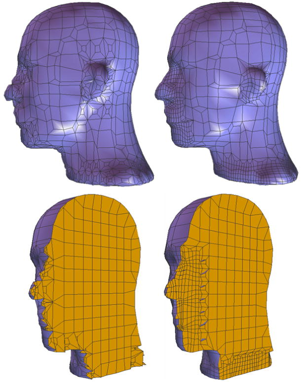
Adaptive hexahedral meshes from Method 1 (left) and Method 2 (right) for the human head. Top row shows the boundary isosurfaces, it is obvious that Method 1 generates a poorly-shaped nose as was shown in Figure 7. Bottom row shows cross sections, the right part of elements are removed.
Fig. 14.
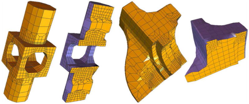
Sharp features are preserved. From left to right: an adaptive quad mesh of a mechanical part, an adaptive hex mesh of a mechanical part, an adaptive quad mesh of a fandisk, and an adaptive hex mesh of a fandisk.
6 Mesh Adaptivity
In order to generate accurate meshes with the minimal number of elements and vertices, it is important to choose a good error metric to decide where we should generate a finer mesh and where a coarser mesh should be kept. There are three main ways to control the mesh adaptivity. Users can also design an error function based on their specific requirements.
Feature sensitive error function
Areas that users are interested in
Finite element calculation results
The feature sensitive error function [38] [39] is defined as the difference of trilinear interpolation functions between coarse and fine octree levels normalized by the gradient magnitude. It is sensitive to areas of large geometric features since it directly measures the surface difference between coarse and fine levels, for example, the facial features (nose, eyes, mouth and ears) in the head model as shown in Figure 13 and 18.
Fig. 18.
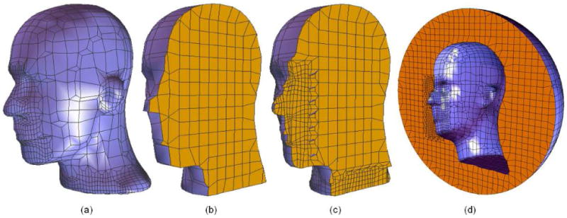
Quadrilateral and hexahedral meshes of the human head. (a) - an adaptive quadrilateral mesh; (b) - the uniform hexahedral mesh at a chosen starting level; (c) - an adaptive interior hexahedral mesh controlled by the feature sensitive error function; (d) - an adaptive exterior hexahedral mesh controlled by the feature sensitive error function.
Sometimes, people are interested in some special areas based on their physical or biological applications. For example, there is a cavity in the structure of the biomolecule called mouse acetylcholinesterase (mAChE) [31] [30]. A finer mesh is required around the cavity area while a coarse mesh needs to be kept in other regions. In this situation, the error function should be defined by regions. Figure 1 shows the adaptive quadrilateral and hexahedral meshes for the biomolecule mAChE, and it is obvious that the mesh adaptivity is controlled by regions.
In finite element simulations, we first need to construct meshes to represent the analyzed geometric domain, then solve ordinary/partial differential equations over it using the finite element method. For accurate and efficient finite element analysis, adaptive meshes are preferable. The mesh adaptivity can be controlled directly by finite element solutions to balance the error of finite element solutions over each element. Figure 21 shows quad meshes of a bubble model. The mesh adaptivity is controlled by its deformation obtained from the finite element analysis.
Fig. 21.

Quadrilateral meshes of a bubble model. (a) - the uniform mesh at a chosen starting level; (b) - an adaptive mesh controlled by finite element solutions (deformation); (c) - a mesh generated by refining all the elements in (a).
7 Quality Improvement
Quality improvement is a necessary step for finite element mesh generation. First we need to choose corresponding quality metrics to measure the quality of quadrilateral and hexahedral meshes. Here we select the scaled Jacobian, the condition number of the Jacobian matrix and Oddy metric [22] as our metrics [17][18][19].
Assume x ∈ ℜ3 is the position vector of a vertex in a quad or a hex, and xi ∈ ℜ3 for i = 1,…, m are its neighboring vertices, where m = 2 for a quad and m = 3 for a hex. Edge vectors are defined as ei = xi − x with i = 1,…, m, and the Jacobian matrix is J = [e1,…, em]. The determinant of the Jacobian matrix is called Jacobian, or scaled Jacobian if edge vectors are normalized. An element is said to be inverted if one of its Jacobians ≤ 0. We use the Frobenius norm as a matrix norm, |J| = (tr(JTJ)1/2). The condition number of the Jacobian matrix is defined as κ(J) = |J‖J−1|, where . Therefore, the three quality metrics for a vertex x in a quad or a hex are defined as follows:
| (2) |
| (3) |
| (4) |
where m = 2 for quadrilateral meshes and m = 3 for hexahedral meshes.
In the process of mesh quality improvement, our goal is to remove inverted elements and improve the worst condition number of the Jacobian matrix. First the averaging method is used to remove inverted elements. We calculate the scaled Jacobian for a vertex in each element, and relocate this vertex by the average of all its neighbors if the Jacobian is negative. Then we calculate the condition number of the Jacobian matrix for a vertex in each quad or hex, and find the vertex with the maximum value. We compute the new position for this vertex using the conjugated gradient method with the condition number (Equation 3) as objective.
If the relocated vertex is an interior node, then we replace the location of this vertex with the calculated new position. If this vertex lies on the boundary, then we calculate its new position and move it toward the isosurface along its normal direction. We keep reducing the maximum condition number for quad or hex meshes until we arrive a given threshold. In this way, we can improve the worst condition number of the Jacobian matrix, as well as improving the other two metrics, the scaled Jacobian and Oddy metric. However, it is possible to produce an invalid mesh containing inverted elements. We choose a ‘smart’ smoothing method [12], which relocates the point only if the mesh quality is improved.
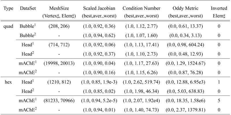
Figure 15 shows the improvement of the worst values of the scaled Jacobian, the condition number and Oddy metric. The histograms of the condition number (Figure 16) show the overall quality of quad and hex meshes for the human head model and a biomolecule mAChE. By Comparing the three quality metrics before and after quality improvement, we can see that the worst parameters are improved significantly.
Fig. 15.
The comparison of the three quality criteria (the scaled Jacobian, the condition number and Oddy metric) before/after the quality improvement for quadrilateral meshes of bubble, head and mAChE. DATA1 – before quality improvement; DATA2 – after quality improvement.
Fig. 16.
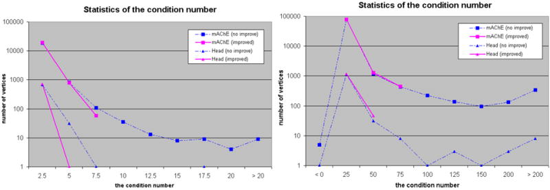
The histogram of the condition number for quadrilateral (left) and hexahedral (right) meshes of mAChE and the human head.
8 Results and Applications
We have developed an interactive program for adaptive and quality quadrilateral/hexahedral mesh extraction and rendering from volumetric data, and plugged it into our LBIE-Mesh software (Level Set Boundary and Interior-Exterior Mesher), which can generate adaptive and quality 2D (triangular/quadrilateral) and 3D (tetrahedral/hexahedral) meshes from volume data. The algorithm of tetrahedral mesh generation is described in [38] [39]. In this software, error tolerances and isovalues can be changed interactively. Our results were computed on a PC equipped with a Pentium III 800MHz processor and 1GB main memory.
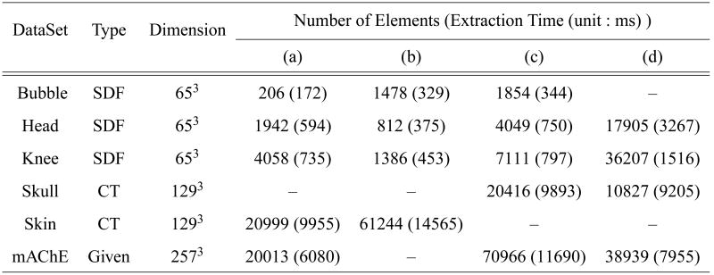
Our algorithm has been used to generate quadrilateral and hexahedral meshes for some signed distance function data such as the bubble (Figure 21), the human head (Figure 18) and the knee model (Figure 19). We have also extracted meshes for the skin and the skull from a CT scanned data (the UNChead, Figure 20), and tested the algorithm on biomolecular data (mAChE, Figure 1). Figure 17 shows the information for each dataset and results. The results consist of the number of elements, the extraction time and images with respect to different isovalues and error tolerances. Extraction time includes octree traversal, QEF computation and mesh extraction.
Fig. 19.
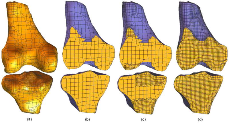
Quadrilateral and hexahedral meshes of the knee. (a) - an adaptive quadrilateral mesh; (b) - the uniform hexahedral mesh at a chosen starting level; (c) - an adaptive hex mesh controlled by the feature sensitive error function; (d) - all the hexahedral elements in (b) are refined.
Fig. 20.

Quadrilateral and hexahedral meshes are extracted from a CT-scanned volumetric data (UNC head). (a) - the quadrilateral mesh of the skin; (b) - the hexahedral mesh of the volume inside the skin; (c) - the quadrilateral mesh of the skull isosurface; (d) - the hexahedral mesh of the skull.
Fig. 17.
Data Sets and Test Results. The CT data sets are re-sampled to fit into the octree representation. Rendering results for each case are shown in Figure 21, 18, 19, 20 and 1. Skull and Skin are extracted from the UNC Head model.
Figure 21 shows the extracted quadrilateral meshes for a bubble, which has been used in the simulation of drop deformation using the finite element method. First, we generate a uniform quad mesh for the original state of the bubble. Then we get finite element solutions such as the deformation from finite element analysis, and use the error of the deformation over each element to control the mesh adaptivity. Finally we can provide an adaptive and quality quad mesh to limit the maximum error of finite element solutions within a threshold.
Some physically-based simulations need both interior and exterior hexahedral meshes. For example, when people are analyzing the electromagnetic scattering over the human head, hex meshes of the volume interior to the head surface and hex meshes exterior to the head surface but inside an outer sphere are needed at the same time. Figure 18 shows the extracted interior and exterior meshes for a head model. The facial features such as nose, eyes, mouth and ears are kept, and fine meshes are generated in those regions. Figure 1 shows another example of interior and exterior hexahedral meshes, the biomolecule mAChE. The mesh adaptivity is controlled by regions, fine meshes are generated in the area of cavity.
9 Conclusions
We have presented an algorithm to extract adaptive and quality quadrilateral and hexahedral meshes directly from volumetric data. First, a bottom-up surface topology preserving octree-based algorithm is used to select a starting octree level, at which we extract uniform meshes with correct topology using the dual contouring isosurface extraction method [15] [38] [39]. Then we extended it to adaptive quadrilateral and hexahedral mesh generation using some predefined templates without introducing any hanging nodes. The position of each boundary vertex is recalculated to approximate the isosurface more accurately. The mesh adaptivity can be controlled in three ways, the feature sensitive error function [38] [39], the areas that users are interested in and finite element solutions. Users can also design their own error function to control the mesh adaptivity according to their specific requirements. Finally, three various quality metrics are selected to measure the mesh quality, and the relaxation based technique is used to improve it. The resulting meshes are extensively used for efficient and accurate finite element calculations. Some of them have been used successfully.
Acknowledgments
An early version of this paper appeared in 13th International Meshing Roundtable conference [37]. We thank Bong-Soo Sohn for several useful discussions, Jianguang Sun for his help with CVC system management, Dr. Gregory Rodin for finite element solutions of drop deformation, Dr. Nathan Baker for providing access to the accessibility volume of biomolecule mAChE and UNC for the CT volume dataset of a human head respectively. This work was supported in part by NSF grants ACI-0220037, CCR-9988357, EIA-0325550, a UT-MDACC Whitaker grant, and a subcontract from UCSD 1018140 as part of the NSF-NPACI project, Interaction Environments Thrust.
Footnotes
References
- 1.Cubit mesh generation toolkit. web site: http://sass1693.sandia.gov/cubit.
- 2.Baehmann P, Wittchen S, Shephard M, Grice K, Yerry M. Robust geometrically based, automatic two-dimensional mesh generation. Int J Numer Meth Engng. 1987;24:1043–1078. [Google Scholar]
- 3.Bajaj C, Warren J, Xu G. A subdivision scheme for hexahedral meshes. The Visual Computer. 2002;18(56):343–356. [Google Scholar]
- 4.Blacker T, Myers R. Seams and wedges in plastering: a 3d hexahedral mesh generation algorithm. Engineering With Computers. 1993;2:83–93. [Google Scholar]
- 5.Blacker T, Stephenson M. Paving: A new approach to automated quadrilateral mesh generation. Int J Numer Meth Engng. 1991;32:811–847. [Google Scholar]
- 6.Canann S. Ph D Dissertation. Brigham Young University; Provo, UT: 1991. Plastering and optismoothing: new approaches to automated, 3d hexahedral mesh generation and mesh smoothing. [Google Scholar]
- 7.Canann S, Tristano J, Staten M. An approach to combined laplacian and optimization-based smoothing for triangular, quadrilateral and quad-dominant meshes. 7th International Meshing Roundtable; 1998. pp. 479–494. [Google Scholar]
- 8.Charalambous C, Conn A. An efficient method to solve the minimax problem directly. SIAM Journal of Numerical Analysis. 1978;15(1):162–187. [Google Scholar]
- 9.Cook WA, Oakes WR. Mapping methods for generating three-dimensional meshes. Computers in Mechanical Engineering. 1982:67–72. [Google Scholar]
- 10.Eppstein David. Linear complexity hexahedral mesh generation. Symposium on Computational Geometry; 1996. pp. 58–67. [Google Scholar]
- 11.Field D. Laplacian smoothing and delaunay triangulations. Communications in Applied Numerical Methods. 1988;4:709–712. [Google Scholar]
- 12.Freitag L. On combining laplacian and optimization-based mesh smoothing techniqes. AMD-Vol 220 Trends in Unstructured Mesh Generation. 1997:37–43. [Google Scholar]
- 13.Freitag L, Ollivier-Gooch C. Tetrahedral mesh improvement using swapping and smoothing. Int J Numer Meth Engng. 1997;40:3979–4002. [Google Scholar]
- 14.Garland M, Heckbert P. Simplifying surfaces with color and texture using quadric error metrics. IEEE Visualization; 1998. pp. 263–270. [Google Scholar]
- 15.Ju T, Losasso F, Schaefer S, Warren J. Dual contouring of hermite data. Proceedings of SIGGRAPH; 2002. pp. 339–346. [Google Scholar]
- 16.Kinney P. Cleanup: Improving quadrilateral finite element meshes. 6th International Meshing Roundtable; 1997. pp. 437–447. [Google Scholar]
- 17.Knupp P. Achieving finite element mesh quality via optimization of the jacobian matrix norm and associated quantities. part i - a framework for surface mesh optimization. Int J Numer Meth Engng. 2000;48:401–420. [Google Scholar]
- 18.Knupp P. Achieving finite element mesh quality via optimization of the jacobian matrix norm and associated quantities. part ii - a framework for volume mesh optimization and the condition number of the jacobian matrix. Int J Numer Meth Engng. 2000;48:1165–1185. [Google Scholar]
- 19.Kober C, Matthias M. Hexahedral mesh generation for the simulation of the human mandible. 9th International Meshing Roundtable; 2000. pp. 423–434. [Google Scholar]
- 20.Lee C, Lo S. A new scheme for the generation of a graded quadrilateral mesh. Computers and Structures. 1994;52(5):847–857. [Google Scholar]
- 21.Mitchell S, Tautges T. Pillowing doublets: Refining a mesh to ensure that faces share at most one edge. 4th International Meshing Roundtable; 1995. pp. 231–240. [Google Scholar]
- 22.Oddy A, Goldak J, McDill M, Bibby M. A distortion metric for isoparametric finite elements. Transactions of CSME, No 38-CSME-32, Accession No 2161. 1988 [Google Scholar]
- 23.Owen S. A survey of unstructured mesh generation technology. 7th International Meshing Roundtable; 1998. pp. 26–28. [Google Scholar]
- 24.Price M, Armstrong C. Hexahedral mesh generation by medial surface subdivision: Part i. Int J Numer Meth Engng. 1995;38(19):3335–3359. [Google Scholar]
- 25.Price M, Armstrong C. Hexahedral mesh generation by medial surface subdivision: Part ii. Int J Numer Meth Engng. 1997;40:111–136. [Google Scholar]
- 26.Schneiders R. A grid-based algorithm for the generation of hexahedral element meshes. Engineering With Computers. 1996;12:168–177. [Google Scholar]
- 27.Schneiders R. Refining quadrilateral and hexahedral element meshes. 5th International Conference on Grid Generation in Computational Field Simulations; 1996. pp. 679–688. [Google Scholar]
- 28.Schneiders R. An algorithm for the generation of hexahedral element meshes based on an octree technique. 6th International Meshing Roundtable; 1997. pp. 195–196. [Google Scholar]
- 29.Schneiders R, Schindler R, Weiler F. Octree-based generation of hexahedral element meshes. 5th International Meshing Roundtable; 1996. pp. 205–216. [Google Scholar]
- 30.Song Y, Zhang Y, Bajaj CL, Baker NA. Continuum diffusion reaction rate calculations of wild type and mutant mouse acetylcholinesterase: Adaptive finite element analysis. Biophysical Journal. 2004;87(3):1558–1566. doi: 10.1529/biophysj.104.041517. [DOI] [PMC free article] [PubMed] [Google Scholar]
- 31.Song Y, Zhang Y, Shen T, Bajaj CL, McCammon JA, Baker NA. Finite element solution of the steady-state smoluchowski equation for rate constant calculations. Biophysical Journal. 2004;86(4):2017–2029. doi: 10.1016/S0006-3495(04)74263-0. [DOI] [PMC free article] [PubMed] [Google Scholar]
- 32.Staten M, Canann S. Post refinement element shape improvement for quadrilateral meshes. AMD-Trends in Unstructured Mesh Generation. 1997;220:9–16. [Google Scholar]
- 33.Talbert J, Parkinson A. Development of an automatic, two dimensional finite element mesh generator using quadrilateral elements and bezier curve boundary definitions. Int J Numer Meth Engng. 1991;29:1551–1567. [Google Scholar]
- 34.Tautges T, Blacker T, Mitchell S. The whisker-weaving algorithm: a connectivity based method for constructing all-hexahedral finite element meshes. Int J Numer Meth Engng. 1996;39:3327–3349. [Google Scholar]
- 35.Teng SH, Wong CW. Unstructured mesh generation: Theory, practice, and perspectives. International Journal of Computational Geometry and Applications. 2000;10(3):227–266. [Google Scholar]
- 36.Weiler F, Schindler R, schneiders R. Automatic goemtry-adaptive generation of quadrilateral and hexahedral element meshes for the fem. Numerical Grid Generation in Computational Field Simulations. 1996:689–697. [Google Scholar]
- 37.Zhang Y, Bajaj C. Adaptive and quality quadrilateral/hexahedral meshing from volumetric data. 13th International Meshing Roundtable; 2004. pp. 365–376. [Google Scholar]
- 38.Zhang Y, Bajaj C, Sohn BS. Adaptive and quality 3d meshing from imaging data. ACM Symposium on Solid Modeling and Applications; 2003. pp. 286–291. [Google Scholar]
- 39.Zhang Y, Bajaj C, Sohn BS. 3d finite element meshing from imaging data. The special issue of Computer Methods in Applied Mechanics and Engineering (CMAME) on Unstructured Mesh Generation. 2004 doi: 10.1016/j.cma.2004.11.026. in press http://www.ices.utexas.edu/∼jessica/meshing. [DOI] [PMC free article] [PubMed]
- 40.Zhu J, Zienkiewicz O, Hinton E, Wu J. A new approach to the development of automatic quadrilateral mesh generation. Int J Numer Meth Engng. 1991;32:849–866. [Google Scholar]


