

Abstract
This tutorial review summarizes the recent advances in the chemical synthesis and potential applications of monodisperse magnetic nanoparticles. After a brief introduction to nanomagnetism, the review focuses on recent developments in solution phase syntheses of monodisperse MFe2O4, Co, Fe, CoFe, FePt and SmCo5 nanoparticles. The review further outlines the surface, structural, and magnetic properties of these nanoparticles for biomedicine and magnetic energy storage applications.
Introduction to nanomagnetism
Nanoparticles (NPs) are of intense current interest for a variety of applications, not only for the general miniaturization of devices, but because their physical properties vary dramatically from their bulk counterparts. The case of magnetic NPs is especially interesting as the NP size is comparable to the size of a magnetic domain. This results in two important types of magnetic behavior in NPs, namely single domain ferromagnetic (FM) NPs and superparamagnetic (SPM) NPs.
Like bulk ferromagnets, an array of single domain magnetic NPs can exhibit hysteresis in the magnetization versus field dependence. A traditional bulk ferromagnet experiences an increase in magnetization with increase in field as the domains grow via domain wall movement to result in a net magnetization. However, in an array of single domain particles, the moment of each particle interacts with its neighbors and the field to align in the field direction. The magnetization at which all the moments are aligned in both instances is referred to as the saturation magnetization (Ms). The decrease of the external field to zero in both cases results in the sample retaining a measurable amount of magnetization. The magnetization present after saturation and the subsequent removal of the field is referred to as the remnant magnetization (Mr). The reversal of the field (in the direction opposite to the remnant magnetization) causes the magnetic moments to randomize again, and the field required to bring the net magnetization back to zero is called the coercivity, Hc.1 The key difference between the magnetic behavior of a bulk magnetic material and a collection of single domain FM NPs arises from the mechanism by which the magnetization is cycled through the hysteresis loop. In a bulk material, the magnetization increases in response to the field via domain wall nucleation and rotation as well as the rotation of the magnetization vector away from the easy axis of magnetization. In a single domain nanoparticle, domain wall movement is not possible and only coherent magnetization rotation can be used to overcome the effective anisotropy (K) of the particle.2 Thus the maximum coercivity of a given material as a function of particle diameter actually falls in the single domain range.
The critical diameter for a magnetic particle to reach the single domain limit is equal to
where A is the exchange constant, K is the effective anisotropy constant and Ms is the saturation magnetization.3 For most magnetic materials, this diameter is in the range 10–100 nm, though for some high-anisotropy materials the single domain limit can be several hundred nanometres.3
For a single domain particle, the amount of energy required to reverse the magnetization over the energy barrier from one stable magnetic configuration to the other is proportional to KV/kBT where V is the particle volume, kB is Boltzmann's constant and T is temperature.4 If the thermal energy is large enough to overcome the anisotropy energy, the magnetization is no longer stable and the particle is said to be superparamagnetic (SPM). That is, an array of NPs each with its own moment can be easily saturated in the presence of a field, but the magnetization returns to zero upon removal of the field as a result of thermal fluctuations (i.e. both Mr and Hc are zero). This behavior is analogous to conventional paramagnets, only instead of individual electronic spins displaying this fluctuating response, it is the collective moment of the entire particle, hence the term “superparamagnetism”.5 The temperature at which the thermal energy can overcome the anisotropy energy of a NP is referred to as the blocking temperature, TB.4 For an array of NPs with a distribution in volume, TB represents an average characteristic temperature and can be affected by inter-particle interactions as well as the timescale over which the measurement is performed due to the magnetic relaxation of the particles.6 Keeping these caveats in mind, TB as the general transition from ferromagnetism to superparamagnetism is one of the most important quantities that define the magnetic behavior of an assembly of particles. Fig. 1 shows a schematic illustrating the difference in the magnetization versus field behavior of an array of single domain magnetic NPs in the blocked state (Fig. 1a) and an array of SPM NPs (Fig. 1b).
Fig. 1.
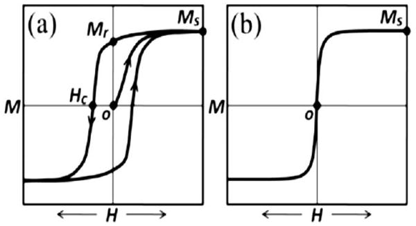
Schematic illustration of (a) a typical hysteresis loop of an array of single domain ferromagnetic nanoparticles and (b) a typical curve for a superparamagnetic material.
The magnetic instability of small, SPM NPs has proven to be a challenge in the current design of magnetic data storage.7 “Beating the superparamagnetic limit” by developing synthesis routes for NPs with high anisotropy constants is one way to try to compensate for thermal fluctuations that become dominant at small particle volumes.8 It has also been found that the ability to synthesize small NPs with high coercivity and anisotropy could lead to significant improvements for the next generation of permanent magnets.9
On the other hand, the properties that characterize SPM NPs—namely high saturation magnetization accompanied by a low saturation field and no remnant magnetization—have proven to be ideal for biomedical applications. The lack of prominent inter-particle interactions, which normally lead to aggregations of particles, enable the synthesis of NP dispersions (ferrofluids) which can be injected into biological systems and manipulated by external field gradients. Such dispersions are currently finding applications in site specific treatments such as targeted drug delivery, localized heating of cancerous cells (hyperthermia), and magnetic resonance imaging (MRI) contrast enhancement.10
In this review, we discuss the general chemistry used to obtain monodisperse magnetic NPs and to functionalize these NPs for biomedical applications with special emphasis on bioimaging. We also introduce how two different NP species can be independently synthesized and combined to fabricate exchange-spring nanocomposite magnets for energy storage applications.
Chemical synthesis of magnetic nanoparticles
A variety of chemical methods have been developed for preparing monodisperse magnetic nanoparticles (NPs).11 Here we briefly review recent advances in organic solution phase syntheses of monodisperse magnetic NPs from thermal decomposition of organometallic precursors and metal salt reduction.
Nanoparticle synthesis in general
A commonly used route to synthesize monodisperse NPs in the solution phase is to separate nucleation and growth steps during the synthesis. In the theory developed by LaMer,12 a burst nucleation occurs when the monomers quickly increase over critical supersaturation without further formation of nuclei afterwards.13 The produced nuclei then grow at the same rate, giving monodisperse particles. The process is illustrated in Fig. 2a. However, small NPs have an extremely high surface area to volume ratio and agglomerate easily to minimize their surface energy. To prevent this agglomeration from occurring, surfactant molecules have to be used to coat the particle surface. The repulsive forces introduced by the surfactant molecules around any two NPs offer the much-needed long-term NP stabilization.
Fig. 2.
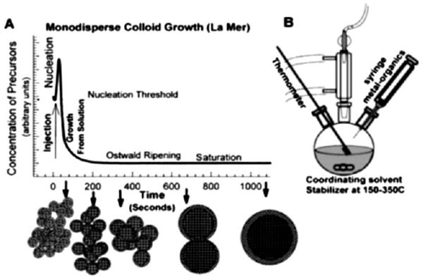
(a) Schematic illustration of the LaMer model: separate nucleation and growth for the synthesis of monodisperse nanoparticles; (b) a typical “hot-injection” set-up to achieve the burst nucleation in (a). Reprinted from ref. 13 with permission from Annual Reviews.
Fig. 2b illustrates a schematic lab set-up utilizing the frequently applied “hot-injection” procedure to achieve the burst nucleation by rapid introduction of reagents into the reaction vessel. Alternatively, a so-called “heating-up” strategy is also widely applied14 which heats up a pre-mixed solution of precursors, surfactants, and solvent to a certain temperature to initiate the particle clustering and growth. Recent synthetic advances have indicated that both hot-injection and heating-up procedures are capable of yielding highly monodisperse NPs (standard deviation in diameter σ < 10%) via fine control of the reaction parameters.11,13,14
Synthesis of magnetic nanoparticles via thermal decomposition reaction
One of the simplest and most important methods for preparing magnetic NPs is via the decomposition of metal precursors, most often of the organometallic complexes. Due to their metastable nature, such organometallic complexes can readily undergo decomposition by mild agitation, such as heat, light, or even sound.11
Metal carbonyls and their related derivatives are one representative class of organometallic complexes and are usually applied to the synthesis of metallic NPs. These reactive carbonyls have a strong tendency to dissociate the carbonyl groups when heated, leaving the zero-valent metal centers to nucleate and grow into NPs.15 Iron(0) pentacarbonyl, Fe(CO)5, has been used to produce monodisperse magnetic iron and iron oxide NPs in the presence of surfactants. For example, Fe NPs with various sizes ranging from 5 nm to 19 nm were synthesized by thermal decomposition of Fe(CO)5 in dioctyl ether solvent and oleic acid (OA) and oleylamine (OAm) as surfactants.15 Monodisperse face centered cubic Co (fcc-Co) NPs with multi-twinned structures were fabricated by thermolysis of dicobalt octacarbonyl, Co2(CO)8, in diphenyl ether with OA and tributylphosphines.16 ε-Co NPs were produced by thermolysis of Co2(CO)8 using trialkylphosphine oxides as surfactant.16,17 CoFe alloy particles were made by simultaneous decomposition of Fe(CO)5 and Co2(CO)8 in 1,2-dichlorobenzene.18
However, the metallic NPs described above are extremely reactive and subject to fast oxidation. To stabilize these active NPs, an efficient surface coating is needed to prevent oxygen from penetrating through the coating layer. The authors recently reported a simple one-pot synthesis of monodisperse Fe NPs (σ < 7%) by thermal decomposition of Fe(CO)5 in 1-octadecene (ODE) with OAm.19 Fig. 3 shows TEM images of the Fe NPs prepared with this method. The as-synthesized Fe NPs were unstable and were readily oxidized during treatment in ambient conditions, producing an amorphous Fe3O4 layer around the metallic Fe core (Fig. 3a). However, when trimethylamine N-oxide, Me3NO, was added to the Fe NP dispersion before its exposure to air, a well-crystallized Fe3O4 shell was formed, giving core–shell Fe/Fe3O4 NPs (Fig. 3b). The core–shell NPs were SPM at room temperature with a saturation magnetization of 103 emu g−1 and were stable against deep oxidation upon their further exposure to air. In contrast, the as-synthesized Fe NPs without Me3NO treatment were subject to fast oxidation and rapid agglomeration in the dispersion.
Fig. 3.
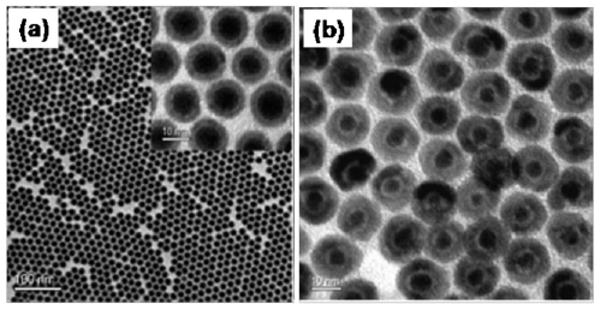
TEM images of (a) the as-synthesized 8 nm/2.5 nm Fe/Fe3O4 NPs (inset: HRTEM) and (b) the 5 nm/5 nm Fe/Fe3O4 NPs prepared by controlled oxidation of Fe NPs. Reproduced from ref. 19 with permission from the American Chemical Society.
Synthesis of magnetic nanoparticles via metal reduction
Magnetic NPs have also been frequently synthesized by the reduction of metal salts using reducing agents in the presence of surfactant molecules. Compared to the thermal decomposition approaches, where unstable organometallic precursors are involved, metal reduction methods offer a larger variety of stable metal precursors, such as oxides, nitrates, chlorides, acetates, and acetylacetonates.15 Conventionally, hydride-based reducing agents, such as sodium borohydride and lithium superhydride, are used for metal salt reduction. More recently, organic reducing agents have been employed for such reduction. These reducing agents include polyols, hydrazine and dihydrogen gas.20
Monodisperse ε-Co NPs have been prepared via the reduction of cobalt chloride using lithium triethylborohydride (LiBEt3H, superhydride) in dioctyl ether with the presence of OA and trialkylphosphine surfactants.16 The trialkylphosphine surfactants with shorter alkyl chains allowed faster growth, thus favored the production of larger particles, and vice versa. The synthesis of FeCo particles was achieved by simultaneous co-reduction of ferrous sulfate and cobalt chloride salts using sodium borohydride, while hollow FeCo was prepared similarly using potassium borohydride.21 The reduction of FeCl2 and Pt(acac)2 in diphenyl ether by LiBEt3H in the presence of OA-OAm gave 4 nm FePt particles.22
Metal reduction using polyols, especially the ones with adjacent hydroxyl groups and long hydrocarbon chains, has become much more popular recently due to their versatility as solvent, reducing agent and surfactant during the reaction. Frequently used poly-ethylene glycols (poly-EG) have been applied to fabricate various magnetic metal and alloy NPs.11 Moreover, the polyol process has been extended to the synthesis of rare-earth hard magnets. SmCo5 particles were prepared by heating a tetraethyleneglycol (TEG) solution of SmCl3 and Co(acac)3 in the presence of polyvinyl pyrrolidone (PVP) at 300 °C.23 The particles had a room temperature Hc of 1100 Oe. Very recently, via co-reduction of Sm and Co nitrates in TEG with the presence of PVP, air-stable 10 × 100 nm blade-like SmCo nanorods were made.23 Their Hc and Ms were 6.1 kOe and 40 emu g−1 at room temperature, and 8.5 kOe and 44 emu g−1 at 10 K.
1,2-Alkanediols represent another group of polyols. Monodisperse Fe3O4 NPs (4 nm–18 nm) were prepared by reduction of Fe(acac)3 with 1,2-hexadecanediol in benzyl ether in the presence of OA-OAm. Excess diol further reduced Fe3O4 into Fe NPs.24 This procedure has been extended to the syntheses of other ferrites (MFe2O4, M = Co, Mn, etc.). The 16 nm Fe3O4 NPs were SPM at room temperature (Ms = 83 emu g−1), and became ferromagnetic at 10 K (Hc = 450 Oe). In comparison, the 16 nm CoFe2O4 NPs had a room temperature Hc of 400 Oe and a much larger Hc of 20 kOe at 10 K. Recently, FeCo alloy NPs were synthesized via 1,2-hexadecanediol reduction of Fe(acac)3 and Co(acac)2 in OA-OAm under an Ar + 7% H2 atmosphere.24 The resulting 20 nm FeCo NPs had an Ms of 207 emu g−1. The Ms reached 230 emu g−1 upon thermal annealing under which a robust carbon coating was formed around the CoFe NPs.
Alkyl amines and acids have also been proven to have reducing abilities at elevated temperatures. Using this chemistry, nanocubes and hollow-frames have been synthesized.25 The process utilized high temperature (380 °C) decomposition of OA to give reductive species, such as C, CO, and H2, and to reduce Fe(ii)-stearate into metallic Fe particles. The addition of extra sodium oleate led to the formation of Fe nanocubes, and further heating gave hollow nanoframes. The formation of the hollow structure was due to the severe molten salt corrosion. Hollow Co particles were made by simultaneous fast out-diffusion of CoO and surface reduction of the oxides by OAm.25 FeO NPs and nanocubes have also been made by reduction of Fe(acac)3 in an OA-OAm mixture at 300 °C.26
Solid state processes utilizing high temperature reduction with alkaline metals have been used to reduce rare earth metal salts. SmCo5 nanocrystalline hard magnets were prepared by reductive annealing of core-shell structured Co/Sm2O3 particles27 with metallic Ca at 900 °C to reduce Sm2O3 and to promote interfacial diffusion between Sm and Co. KCl was used as the dispersion medium to facilitate reduction and to prevent NPs from growing into large single crystals. The coercivity of the magnets reached 24 kOe at 100 K and 8 kOe at room temperature with remnant magnetization values of 40–50 emu g−1.
The combination of thermal decomposition and metal salt reduction are often applied to make alloy NPs, particularly FePt NPs. For example, simultaneous thermolysis of Fe(CO)5 and reduction of Pt(acac)2 in the presence of 1,2-hexadecanediol was a common route to monodisperse FePt NPs.8 The composition and the size of the resulting FePt NPs were controlled by tuning the Fe(CO)5 : Pt(acac)2 ratio and/or precursor : surfactant ratio. 7 nm FePt cube-like NPs were synthesized under similar conditions but without 1,2-hexadecanediol.8 More recently, FePt nanowires or nanorods from 20 to 200 nm were made by thermal decomposition of Fe(CO)5 and reduction of Pt(acac)2 in a mixture of OAm and ODE at 160 °C and the aspect ratio of the rods was controlled by the volume ratio of OAm : ODE.8 Polyol reduction of Sm(acac)3 was combined with thermolysis of Co2(CO)8 to synthesize small (<10 nm) SmCo5 particles with a coercivity of 2.2 kOe at 5 K and a calculated anisotropy (K) of about 2.1 × 10 erg cm−3 which is about 1% of bulk SmCo5.28
Magnetic nanoparticles for biomedical applications
Magnetic NPs, especially superparamagnetic (SPM) NPs, are attractive magnetic probes for biological imaging and therapeutic applications.29 At a core diameter of less than 20 nm and overall hydrodynamic diameter of less than 50 nm, these NPs are of a size that is comparable to the nuclear pore size (∼50 nm) and are much smaller than a cell (normally 10–100 mm). Once coupled with a target agent, they can serve as a nano-vector and interact specifically with biomolecules of interest through well-established biological interactions, providing controllable means of magnetically tagging a bio-entity. Under the normal range of magnetic field strengths used in magnetic resonance imaging (MRI) scanners (usually higher than 1 tesla), these SPM NPs in the targeted area can be magnetically saturated, establishing a substantial locally perturbing dipolar field that leads to a marked shortening of proton relaxation (T2 relaxation) in the MRI process and giving a “darker” image of the targeted area over the biological background. Furthermore, under an alternating (AC) magnetic field with controlled field amplitude and field reversal frequency, magnetization of the SPM NPs attached to the bio-entity can be switched back and forth. This magnetization re-orientation creates friction between the NP and its surrounding liquid medium, or between the magnetic easy axis of the particle and the atomic lattice within the NP structure. In both cases, the energy originating from this friction is converted to thermal energy, and these SPM NPs function as a heater to heat the area they target to. This magnetic field induced NP heating is known as magnetic fluid hyperthermia and has been studied extensively for future cancer therapy.
Surface functionalization of magnetic nanoparticles
Due to the monodispersity in size, shape and composition, high moment SPM NPs prepared in organic phase syntheses are ideal for biomedical applications. However, these SPM NPs are normally stabilized by surfactants like oleic acid and/or oleylamine and are hydrophobic. To make these NP hydrophilic for biological applications, their surfaces are often functionalized via surfactant addition or surfactant exchange, as illustrated in Fig. 4. Surfactant addition is achieved through the adsorption of amphiphilic molecules that contain both a hydrophobic segment and a hydrophilic component. The hydrophobic segment forms a double layer structure with the original hydrocarbon chain, while hydrophilic groups are exposed to the outside of the NPs, rendering them water-soluble. Surfactant exchange is the direct replacement of the original surfactant with a new bifunctional surfactant. This bifunctional surfactant has one functional group capable of binding to the NP surface tightly via a strong chemical bond and the second functional group at the other end has polar character so that the NPs can be dispersed in water or be further functionalized.
Fig. 4.
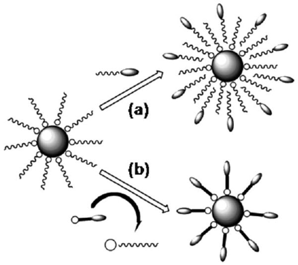
Schematic illustration of NP surface functionalization via (a) surfactant addition and (b) surfactant exchange.
The surfactant addition strategy was first developed for making water-soluble quantum dots and was then successfully demonstrated for dispersing magnetic NPs into aqueous media. The amphiphilic ligands possess a lipophilic structure (i.e. hydrocarbon chain) and hydrophilic polar functional groups (either ionic or uncharged), such as poly(maleic anhydride-alt-1-octadecene)-PEG block copolymer, or amphiphilic PEG-phospholipids.30 The introduction of amphiphilic ligands to as-synthesized nanoparticles results in the formation of a robust double layer around the particles. Recently, Dai's group developed a PEG-modified phospholipid micelle coating for functionalization of high moment SPM FeCo NPs (Fig. 5).31 The hydrocarbon chains of the phospholipid are bound to the graphitic shells of FeCo NPs via hydrophobic interactions to form stable double layers while the PEG chains are exposed to aqueous media, leading to high water solubility. Very recently, Shin et al. used the same strategy to encapsulate hollow manganese oxide nanoparticles into a PEG-phospholipid shell to provide them with good biocompatibility.32
Fig. 5.
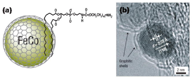
(a) Schematic representation of the amphiphilic micelle coating of the CoFe NPs; (b) high-resolution TEM image of a single CoFe NP. Adapted from ref. 31 with permission from Nature Publishing Group.
Similarly, various amphiphilic polymers, such as polystyrene-poly acrylic acid block copolymer (PS-PAA), tetradecylphosphonate and polyethylene glycol-2-tetradecyl ether, have been successfully used for transferring hydrophobic NPs from organic solvents to aqueous solution.33 Various commercially available amphiphilic polymers provide different functional groups, including carboxylic acid, thiol, amine, carbonyl, and biotin, for immobilization of various biological moieties, such as peptides, proteins, oligonucleotides.
In comparison to the amphiphilic micelle coating, the bifunctional ligand exchange strategy provides in principle better colloidal stability of the magnetic NPs in physiological conditions due to strong interactions between the bidentate or multidentate functional groups and the iron oxide surface. Xu et al. reported that bidentate ligand, dopamine, can coordinate to the surface of iron oxide as a result of improved orbital overlap of the five-membered ring and a reduced steric effect on the iron complex (Fig. 6a).34 The resulting NPs showed excellent stability in physiological conditions. The utilization of a mixture of PEG ligands (dopamine-PEG and thiol terminated PEG) not only enhances colloidal stability of FePt alloy NPs in aqueous media but also provides an easy way to immobilize biomolecules onto magnetic NPs.35 Carboxyl acid terminated dopamine-PEG successfully transferred the Fe/Fe3O4 core–shell magnetic nanoparticles from an organic solvent to aqueous media with relatively high stability (Fig. 6b).19 Very recently, Wang et al. have synthesized Fe3O4 NPs coated with an amine-terminated PEG ligand, which is readily attached to various molecules, for example chromone, for drug delivery.36
Fig. 6.
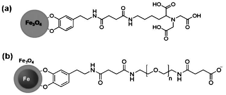
Magnetic Fe3O4 NPs with bifunctional ligands. (a) Surface coating of iron oxide with a dopamine-termination. (b) Water-soluble Fe/Fe3O4 core–shell nanoparticles coated with bifunctional PEG ligands.
The ligand exchange strategy was also developed to replace hydrophobic ligands on magnetic NPs with organosilanes possessing various functional groups.37 The alkoxyl moieties of organosilanes associate with the metal oxide by forming a covalent bond with surface hydroxyl groups via dehydration or esterification. It was found that amino-, carboxylic acid- and polyethylene glycol-terminated silanes not only make the magnetic NPs highly stable and water-soluble, but also render them with diverse functionalities for subsequent bioconjugation. Many small bifunctional molecules, such as cystamine and 2,3-dimercaptosuccinic acid (DMSA), have also been used for replacement of hydrophobic layers via either the formation of metal–S bonds or chelate bonding of the carboxylate groups to the magnetic NPs.37 Unlike PEGylated or other polymer-based NPs, the hydrodynamic particle size remains sufficiently small after ligand exchange coating.
In situ coating becomes popular as it requires no subsequent surfactant exchange. Magnetic NPs have been made in the presence of a variety of carboxylates (i.e. citric acid), phosphates, phosphonates, or other multidentate ligands for obtaining biocompatible and thermodynamically stable dispersions of NPs in aqueous media.38 Xie et al. developed a new strategy to synthesize ultrasmall, water-soluble NPs by combining the in situ coating with post-synthesis functionalization.39 A small ligand 4-methylcatechol (4-MC) was used as the surfactant to stabilize ultrasmall iron oxide NPs during the synthesis. Like dopamine, 4-MC forms a strong chelate bond with the surface of iron oxide. A cyclic RGD peptide (c(RGDyK)) was directly conjugated to 4-MC functionalized NPs via the Mannich reaction between the aromatic ring of 4-MC and amine groups of c(RGDyK). The NPs showed the desired biocompatibility and specificity to target αvβ3-rich tumor cells.
Superparamagnetic nanoparticles as contrast agents in MRI
MRI is one of the most powerful non-invasive imaging modalities utilized in clinical medicine. It is based on the principle that protons align and precess along an applied magnetic field. Upon applying a transverse radiofrequency pulse, these precessed protons are perturbed from the magnetic field direction. The subsequent process, through which the pulsing field is turned off to allow protons to return to their original state, is referred to as relaxation. Two independent relaxation processes, longitudinal relaxation (T1-recovery) and transverse relaxation (T2-decay), are utilized to generate a bright and a dark MR image, respectively. Local variations in relaxation, corresponding to image contrast, arise from proton density as well as the chemical and physical nature of the tissues within the specimen. Upon accumulation in tissues, SPM NPs act typically as T2 contrast agents to provide a dark image and the contrast enhancement is proportional to the magnetization magnitude.
As the magnetization value of a SPM NP at a certain magnetic field is dependent on the size and magnetocrystalline anisotropy of the NP, SPM NPs with different sizes and structures have been compared for their contrast effects in MRI.37 In a recent comprehensive study on ferrite NPs for MRI application,38 12 nm MnFe2O4 NPs were shown to have the highest mass magnetization value of 110 (emu per mass of magnetic atoms). This value is reduced to 101, 99 and 85 (emu per mass of magnetic atoms) for Fe3O4, CoFe2O4 and NiFe2O4, respectively. The spin–spin relaxation time (T2)-weighted MR images for each sample at 1.5 tesla (T) are consistent with the magnetization results, with MnFe2O4 NPs showing the strongest MR contrast effect with a relaxivity value reaching 358 mM−1 s−1, much larger than 218, 172 and 152 mM−1 s−1 for Fe3O4, CoFe2O4 and NiFe2O4 NPs, respectively. This size and structure dependent relaxivity of MnFe2O4 NPs can be seen in Fig. 7, from which one can conclude that larger NPs have a large contrast effect, but at the same size, MnFe2O4 NPs have the largest contrast enhancement due to the small magnetocrystalline anisotropy and easy magnetization reversal in the MnFe2O4 structure.
Fig. 7.
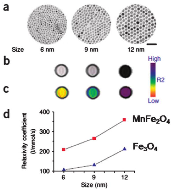
Size-dependent MR contrast effect of MnFe2O4 and Fe3O4 NPs. (a) TEM images of MnFe2O4 NPs (scale bar, 50 nm), (b) T2-weighted MR images, (c) color maps of 6, 9 and 12 nm MnFe2O4 NPs, and (d) a plot of NP size versus R2 relaxivity. Reproduced from ref. 37 with permission from Nature Publishing Group.
The cancer detection sensitivity of these ferrite NPs have been further evaluated. In a recent test, the MnFe2O4 NPs were coupled with the cancer-targeting Herceptin, an antibody specifically binding to the HER2/neu marker over-expressed on the surface of breast and ovarian cancers.37 Fig. 8 shows the color coded MRI of a mouse implanted with the cancer cell line NIH3T6.7 and treated with 50 mg of NP–Herceptin. It can be seen that the tumor treated with the MnFe2O4–Herceptin NPs shows color changes from red to blue in the color-coded MR images (Fig. 8a–c). In contrast, those treated with the Fe3O4–Herceptin NPs at the same dosage have no apparent change in the color-coded MR images (Fig. 8d–f). These indicate that the high MR sensitivity of MnFe2O4–Herceptin conjugates enables the MR detection of tumors.38 An even higher MRI sensitivity can be achieved by using high moment SPM NPs. In a recent demonstration, SPM CoFe NPs were made biocompatible and exhibited an r2 relaxivity of 644 mM−1 s−1.31
Fig. 8.
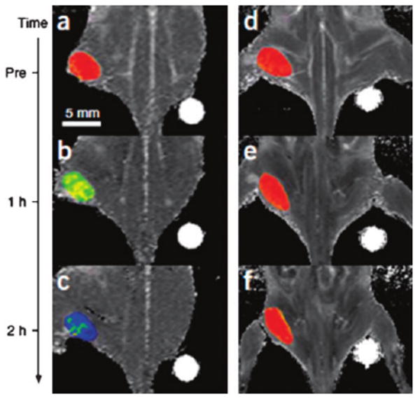
Color maps of T2-weighted MR images of a mouse implanted with the cancer cell line NIH3T6.7 at different time points after injection of MnFe2O4–Herceptin (a–c) and Fe3O4–Herceptin (d–f) conjugates. Adapted from ref. 37 with permission from Nature Publishing Group.
Ultra-small Fe3O4 NPs (<10 nm in hydrodynamic diameter) are also attractive for tumor-specific detection. In a recent demonstration, Fe3O4 NPs with a 4.5 nm core size were synthesized and conjugated with c(RGDyK) peptide.39 The targeting ability of the c(RGDyK)–Fe3O4 NPs to integrin αVβ3 in vivo was evaluated by T2-weighted fast spin-echo MR imaging with mice bearing U87MG tumors. The r2 relaxivity of the c(RGDyK)-Fe3O4 NPs was measured to be 165 mM−1 s−1, which is larger than that of the commercial Feridex NPs (104 mM−1 s−1) with similar core size. The tumor MR signal intensity decreases significantly after injection of c(RGDyK)–Fe3O4 NPs (Fig. 9a and b). Such signal reduction is significantly inhibited in the presence of a blocking dose of c(RGDyK) peptide (10 mg kg−1) (Fig. 9c), proving the specificity of the particle targeting. To chemically characterize the preferred Fe3O4 NP uptake, Prussian blue staining is employed to visualize the disposition of the c(RGDyK)–Fe3O4 NPs in the tissue samples obtained after the MR scan at the 4 h time point. Prominent blue spots on the U87MG tumor slices are observed (Fig. 9d) and the blue spots are significantly reduced in the presence of free c(RGDyK) (Fig. 9e), further confirming that the accumulation of c(RGDyK)–Fe3O4 NPs is specifically mediated by integrin αvβ3 binding.
Fig. 9.
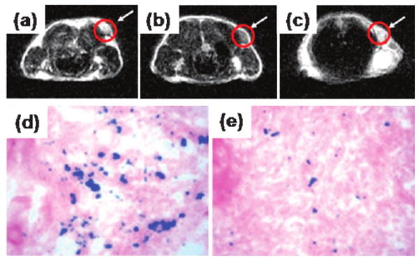
MRI of the cross section of the U87MG tumors implanted in a mouse: (a) without NPs, (b) with the injection of 300 μg of c(RGDyK)–Fe3O4 NPs, and (c) with the injection of a blocking dose of c(RGDyK) then c(RGDyK)–Fe3O4 NPs; and Prussian blue staining of U87MG tumors in the presence of (d) c(RGDyK)–Fe3O4 NPs and (e) a blocking dose of c(RGDyK) and then c(RGDyK)–Fe3O4 NPs. Reproduced with permission from ref. 39.
Nanoparticles for magnetic energy storage applications
An ideal permanent magnetic material emanates a large enough magnetic field such that after it is magnetized it maintains a robust magnetic moment. On the hysteresis loop, this corresponds to a high remnant magnetization (Mr). However, for long-term stability it must also not be easily demagnetized. This corresponds to a large coercivity (Hc). Unfortunately, materials with high remnant magnetization all tend to be magnetically “soft” (coercivity less than∼1000 Oe) and materials that are magnetically “hard” (coercivity greater than ∼1000 Oe) tend to have low remnant magnetization. Until recently, finding the ideal permanent magnetic material has involved a trade-off of these two characteristics and the need to strike a balance between high magnetic moment and high coercivity.
A figure of merit for evaluating the quality of a permanent magnet takes these factors into consideration and is referred to as the maximum energy product, or (BH)max. The (BH)max for a material can be found first by converting the heretofore discussed M–H curve into a B–H curve via the relation B = μ0M + H. Since permanent magnetism is assessed with respect to the magnetostatic energy stored within the magnetic material, it is only the magnetized state (second quadrant of the B–H curve) that is of interest. By plotting the energy product (BH) from the second quadrant versus either B or H, one can identify (BH)max as the maximum. Conceptually, (BH)max corresponds to the area of the largest rectangle that can fit inside the second quadrant of the hysteresis loop.
While it would seem that the coexistence of the two main criteria for useful permanent magnets (Mr and Hc) are naturally incompatible, hard–soft magnetic composite materials are a viable and oft-used route for permanent magnet applications. Hard–soft magnetic composites are materials composed of two phases: the hard magnetic phase (high coercivity) and the soft magnetic phase (high remnant magnetization). When the two phases are properly coupled via exchange interactions across the interface, the result is a smooth hysteresis curve which exhibits the desirable properties of both phases. This type of coupled structure, termed an “exchange-spring”, was first proposed by Kneller and Hawig in 199140 though the actual behavior was observed earlier by Coehoorn et al.41 in the melt-spun and annealed Nd2Fe14B–Fe3B–Fe composite system. Later, Skomski and Coey42 theorized that the optimal exchange-spring system could yield a (BH)max of up to 120 MG Oe, more than three times that of commercially available permanent magnets. In the years that followed, groups have made exchange-spring thin film multilayers and composites by a variety of methods including magnetron sputtering, melt-spinning, mechanical alloying, and hydrogen-assisted processes.43
There are several compelling reasons to use chemical synthesis to produce NPs of the hard and soft phases necessary for exchange-spring permanent magnets. Most importantly, exchange coupling of the hard and soft magnetic phases is optimized on the nanoscale. A robust coupling between the phases is necessary to achieve coherent magnetic switching throughout the structure. The dimensions of the soft phase dominate the nucleation characteristics of the composite, and it has been shown that when the dimensions of the soft phase are kept smaller than twice the width of the domain wall δh = π√(Ah/Kh) of the hard phase, the soft phase can be thoroughly pinned by the hard phase and no inhomogeneous switching should occur.43 For the most commonly used hard phases, the domain wall width falls in the range of 3–15 nm,3 which corresponds well to the NP size following common chemical synthesis procedures.
Secondly, chemical synthesis of NPs affords fine control over chemical phase. Currently, many of the conventional approaches to hard magnetic materials fabrication result in the presence of impurity phases, most commonly α-Fe. The synthesis methods described throughout this review have been found to yield high-purity materials while avoiding unwanted secondary phases.
Lastly, the chemical synthesis of both hard and soft magnetic NPs allows for the optimization of physical properties including magnetic response, composite density, and even grain size. It is well-documented that the manipulation of synthesis parameters such as polarity and amounts of solvents and surfactants can lead to vast differences in particle morphology resulting in spheres, cubes, rods, and other shapes. Controlling particle aspect ratio can lead to higher magnetic anisotropy in nanoparticles due to the added shape anisotropy contribution, and changing particle shape from spherical to orthorhombic can increase the particle packing density leading to a higher (BH)max. Grain size can be manipulated via the controlled assembly of the hard and soft phases.44 While similar morphologies for hard and soft particles lead to a more thorough mixing of the two phases, and thus smaller grain sizes, differences in phase size and shape can lead to limited phase segregation and ultimately larger grain sizes. In this section, we describe progress being made towards the use of magnetic NPs for exchange-spring composite permanent magnets.
Binary assembly of magnetic nanoparticles and exchange-spring composite magnets
While the use of small NPs for both the hard and soft phases of an exchange-spring composite is attractive for the reasons described in the previous section, there has been relatively little progress made in composite systems where both phases were chemically synthesized NPs. This is mainly due to the difficulty in chemically synthesizing high-anisotropy NPs, specifically rare-earth–transition metal alloys such as SmCo5 and Nd2Fe14B. Attempts have mainly focused on embedding soft magnetic NPs into a hard magnetic matrix, usually either a thin film or a ribbon.45 The first demonstration of an exchange-coupled composite formed where both phases originated as NPs was the FePt–Fe3Pt system.44 First, self-assembled 3-D binary arrays of FePt and Fe3O4 magnetic NPs were made by evaporation of a mixture of particle dispersions with controlled volume, concentration, and sizes. The FePt NPs were made following the combination thermal decomposition and metal reduction procedure while the Fe3O4 particles were synthesized via reduction of Fe(acac)3.20 It was found the 4 nm/4 nm FePt/Fe3O4 arrays gave rise to a high-quality hexagonal lattice with random occupation of the two kinds of particles (Fig. 10a), while this binary assembly depended on the size ratio of FePt and Fe3O4 NPs (Fig. 10b). Various binary assembled arrays were then reductively annealed (Ar + 5% H2, 650 °C, 1 h) to desorb the organic surfactants, transform as-assembled fcc-FePt into hard phase fct-FePt, reduce the Fe3O4 into metallic Fe, and to promote partial interdiffusion between Fe and FePt giving a new soft phase of Fe3Pt.
Fig. 10.
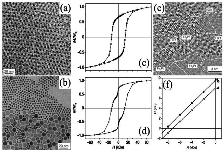
TEM images of (a) randomly occupied 4 nm/4 nm FePt/Fe3O4 array and (b) phase segregated 4 nm/12 nm FePt/Fe3O4. Corresponding hysteresis loops (c) and (d) from the binary arrays of (a) and (b) after annealing. TEM image (e) of the annealed composite from (a). Second-quadrant B–H curves of (e) (dot) and annealed 4 nm FePt array (triangle). Reproduced from ref. 44 with permission from Nature Publishing Group.
The FePt/Fe3Pt nanocomposite resulted from the annealing of a randomly-occupied 4 nm/4 nm FePt/Fe3O4 array (mass ratio of 10 : 1). Magnetic measurements (Fig. 10c) showed a smooth hysteresis loop, implying coherent switching and thus efficient coupling of the hard and soft phases. In comparison, the annealed composite from a phase-segregated 4 nm/12 nm FePt/Fe3O4 assembly gave a kinked loop (Fig. 10d), indicating an uncoupled structure due to the existence of a soft Fe phase (larger Fe3O4 particles inhibited Fe–Pt diffusion) with grain size over twice the domain wall width of the hard FePt phase. HRTEM revealed the Fe3Pt phase with dimensions below 10 nm uniformly dispersed into the sintered FePt matrix (Fig. 10e). The optimized exchange-coupled nanocomposite yielded both high coercivity and remnant magnetization, with an enhanced energy product (BH)max of 20.1 MG Oe (Fig. 10f), which exceeded the theoretical limit of 13 MG Oe for non-exchange-coupled isotropic FePt by over 50%.
However, such binary self-assembly approaches require precise control over the mass and size ratios between the two types of NPs, and subtle management of the assembly conditions as well. A more convenient alternative was developed utilizing single modal bi-magnetic core-shell particles.46 Pre-made 4 nm Fe58Pt42 NPs were coated with a layer of Fe3O4 with tunable thicknesses of 0.5 nm–3 nm via a seed-mediated polyol process. In the resulting core-shell particles, the dimensions of the hard and soft phases were controlled by the shell thickness, and strong exchange coupling was ensured by the direct contact between the core and shell. These FePt/Fe3O4 NPs were further used as building blocks to form exchange-coupled hard magnetic nanocomposites. For instance, upon reductive annealing (Ar + 5% H2, 650 °C, 1 h), the 4 nm/1 nm FePt/Fe3O4 array was transformed into a composite with greatly enhanced hard magnetic properties (Hc = 13.5 kOe and Ms = 1040 emu cc−1) at room temperature. The annealed nanocomposite exhibited an energy product (BH)max of 18 MG Oe.
The ability to use exchange coupling to increase the coercivity often over-shadows the pressing need to increase the remnant magnetization in permanent magnetic materials. The rare-earth based compound SmCo5 has the largest known anisotropy among all materials though it often shows low remnant magnetization.3 Recently, soft phase metallic Fe was employed to fabricate exchange-coupled SmCo5/Fex composite nanomagnets.47 Water-soluble Fe3O4 NPs were co-precipitated with SmCl3 and CoCl2 in aqueous solutions, followed by baking at 120 °C to give Fe3O4 embedded in a Sm-Co-oxide matrix. Reductive annealing was carried out in the presence of metallic Ca at 900 °C, and using KCl as a dispersion medium to facilitate the reduction as well as to prevent sintering and alloying of the SmCo5 and Fe grains. The final SmCo5/Fex (x = 0–2.9) nanocomposites contained hcp-SmCo5 with an average grain size of 29 nm and metallic Fe of 8 nm. The SmCo5/Fe1.5 showed an enhanced remnant magnetization of 56 emu g−1 (25% larger than that of SmCo5), while the SmCo5/Fe0.23 exhibited the largest coercivity of 11.6 kOe.
Conclusion
In this review, we have discussed the importance of magnetic nanoparticles and their unique magnetic properties for technological advances. We have outlined the common chemistry applied for the synthesis of various magnetic nanoparticles with control over NP size, shape, and composition. We have described ways in which superparamagnetic nanoparticles are stabilized and functionalized for biomedical applications such as MRI contrast enhancement. Lastly, we have discussed ways in which self-assembly of magnetic nanoparticles leads to nanocomposite magnets with magnetic properties superior to their individual components, resulting in an enhanced energy product. These illustrated examples further demonstrate that magnetic nanoparticles made from chemical synthesis with controlled size, surface chemistry and magnetic properties are indeed promising for further ultra-high density information storage, highly sensitive medical diagnostics and highly efficient therapeutic applications.
Acknowledgments
The work at Brown has been supported by NIH/NCI 1R21CA12859, ONR/MURI N00014-05-1-0497, DOE/EPSCoR DE-FG02-07ER36374 and DARPA/ARO W911NF-08-1-0249.
Biographies

Natalie A. Frey received dual Bachelor's degrees in Physics and Astrophysics in 2002 from the University of Minnesota. She earned her Master's (2004, Physics) and Doctoral (2008, Applied Physics) degrees from the University of South Florida. As a graduate student she worked as an NSF IGERT (Integrative Graduate Education and Research Traineeship) fellow studying surface and interfacial anisotropy in magnetic nanoparticles for biomedical applications. She is currently a postdoctoral researcher at Brown University where she is working on the synthesis and characterization of nanoparticles for magnetic energy storage.

Sheng Peng was born September 1982, in Hubei, China. He attended the Department of Chemistry, University of Science and Technology of China, and obtained a BSc in Chemistry in 2004. He was admitted by the Department of Chemistry at Brown University in September 2004. He held positions as research and teaching assistant, and has received the Metcalf Fellowship for excellence in academic performance. Since January 2005, he has been focusing on the chemical synthesis of monodisperse nanoparticles. He was recently awarded the Chinese Government Award (2008) for Outstanding Self-Financed Students Abroad. He received his PhD in Chemistry in May 2009.

Kai Cheng received his PhD in Chemistry from University of Vermont in 2007, under the supervision of Prof. Christopher C. Landry. He joined the group of Professor Shouheng Sun at Brown University as a postdoctoral researcher. His current research interests particularly focus on the development of targeted drug delivery systems for cancer therapies.

Shouheng Sun received his PhD in Chemistry from Brown University in 1996. He was a postdoctoral fellow from 1996–1998 and a research staff member from 1998–2004 at the IBM T. J. Watson Research Center. He joined the Chemistry Department of Brown University in 2005. He is now the Professor of Chemistry and Engineering at Brown. His research interests are in nanomaterials synthesis, self-assembly and applications in nanomedicine, catalysis and energy storage.
References
- 1.See for example: Cullity BD. Introduction to Magnetic Materials. Addison-Wesley Publishing Company; Reading MA: 1972. Aharoni A. Introduction to the Theory of Ferromagnetism. Oxford University Press; New York: 1996. Morrish AH. The Physical Properties of Magnetism. Wiley; New York: 1965.
- 2.Stoner EC, Wohlfarth EP. Philos Trans R Soc London, Ser A. 1948;240:599–642. [Google Scholar]
- 3.Skomski R, Coey JMD. Permanent Magnetism. Institute of Physics Publishing; Bristol and Philadelphia: 1999. [Google Scholar]
- 4.Néel L. C R Acad Sci. 1949;228:664–671. [Google Scholar]
- 5.Bean CP. J Appl Phys. 1955;26:1381–1383. [Google Scholar]
- 6.Majetich SA, Sachan M. J Phys D: Appl Phys. 2006;39:R407–R422. [Google Scholar]
- 7.Weller D, Doerner ME. Annu Rev Mater Sci. 2000;30:611–644. [Google Scholar]
- 8.Sun S, Murray CB, Weller D, Folks L, Moser A. Science. 2000;287:1989–1992. doi: 10.1126/science.287.5460.1989. [DOI] [PubMed] [Google Scholar]; Sun S, Fullerton EE, Weller D, Murray CB. IEEE Trans Magn. 2001;37:1239–1243. [Google Scholar]; Chen M, Kim J, Liu JP, Fan H, Sun S. J Am Chem Soc. 2006;128:7132–7133. doi: 10.1021/ja061704x. [DOI] [PubMed] [Google Scholar]; Wang C, Hou Y, Kim J, Sun S. Angew Chem Int Ed. 2007;46:6333–6335. doi: 10.1002/anie.200702001. [DOI] [PubMed] [Google Scholar]
- 9.Li J, Wang ZL, Zeng H, Sun S, Liu JP. Appl Phys Lett. 2003;82:3743–3745. [Google Scholar]; Sun S. Adv Mater. 2006;18:393–403. [Google Scholar]; Zeng H, Sun S. Adv Funct Mater. 2008;18:391–400. [Google Scholar]
- 10.Pankhurst QA, Connolly J, Jones SK, Dobson J. J Phys D: Appl Phys. 2003;36:R167–R181. [Google Scholar]; Lu AH, Salabas EL, Schüth F. Angew Chem Int Ed. 2007;46:1222–1244. doi: 10.1002/anie.200602866. [DOI] [PubMed] [Google Scholar]; Jun YW, Lee JH, Cheon J. Angew Chem Int Ed. 2008;47:5122–5135. doi: 10.1002/anie.200701674. [DOI] [PubMed] [Google Scholar]; LaConte L, Nitin N, Bao G. Mater Today. 2005;8:32–38. [Google Scholar]
- 11.Willard MA, Kurihara LK, Carpenter EE, Calvin S, Harris VG. Int Mater Rev. 2004;49:125–170. [Google Scholar]; Hyeon T. Chem Commun. 2003:927–934. doi: 10.1039/b207789b. [DOI] [PubMed] [Google Scholar]; Cushing BL, Kolesnichenko VL, O'Connor CJ. Chem Rev. 2004;104:3893–3946. doi: 10.1021/cr030027b. [DOI] [PubMed] [Google Scholar]; Gedanken A, Mastai Y. The Chemistry of Nanomaterials. Wiley-VCH; Weinheim, Germany: 2006. [Google Scholar]; Matsunaga T, Okamura Y. Mater Res Soc Symp Proc. 2002;724:N14. [Google Scholar]
- 12.LaMer VK, Dinegar RH. J Am Chem Soc. 1950;72:4847–4854. [Google Scholar]
- 13.Murray CB, Kagan CR, Bawendi MG. Annu Rev Mater Sci. 2000;30:545–610. [Google Scholar]
- 14.Park J, Joo J, Kwon SG, Jang Y, Hyeon T. Angew Chem Int Ed. 2007;46:4630–4660. doi: 10.1002/anie.200603148. [DOI] [PubMed] [Google Scholar]
- 15.Xie J, Sun S. Nanomaterials: Inorganic and Bioinorganic Perspectives - Encyclopedia in Inorganic Chemistry. John Wiley & Sons, Ltd.; 2008. Chemical Synthesis and Surface Modification of Monodisperse Magnetic Nanoparticles. [Google Scholar]; Huber DL. Small. 2005;1:482–501. doi: 10.1002/smll.200500006. [DOI] [PubMed] [Google Scholar]; Farrell D, Majetich SA, Wilcoxon JP. J Phys Chem B. 2003;107:11022–11030. [Google Scholar]; Farrell D, Cheng Y, McCallum RW, Sachan M, Majetich SA. J Phys Chem B. 2005;109:13409–13419. doi: 10.1021/jp050161v. [DOI] [PubMed] [Google Scholar]
- 16.Sun S, Murray CB, Doyle H. Mater Res Soc Symp Proc. 1999;577:395–398. [Google Scholar]; Murray CB, Sun S, Gaschler W, Doyle H, Betley TA, Kagan CR. IBM J Res Dev. 2001;45:47–56. [Google Scholar]; Murray CB, Sun S, Doyle H, Betley TA. MRS Bull. 2001;26:985–991. [Google Scholar]
- 17.Sun S, Murray CB. J Appl Phys. 1999;85:4325–4330. [Google Scholar]; Puntes VF, Krishnan KM, Alivisatos P. Appl Phys Lett. 2001;78:2187–2189. [Google Scholar]; Dinega DP, Bawendi M. Angew Chem Int Ed. 1999;38:1788–1791. doi: 10.1002/(SICI)1521-3773(19990614)38:12<1788::AID-ANIE1788>3.0.CO;2-2. [DOI] [PubMed] [Google Scholar]
- 18.Hütten A, Sudfeld D, Ennen I, Reiss G, Wojczykowski K, Jutzi P. J Magn Magn Mater. 2005;293:93–101. [Google Scholar]
- 19.Peng S, Wang C, Xie J, Sun S. J Am Chem Soc. 2006;128:10676–10677. doi: 10.1021/ja063969h. [DOI] [PubMed] [Google Scholar]
- 20.Seip C, O'Connor C. Nanostruct Mater. 1999;12:183–186. [Google Scholar]; Gibot P, Tronc E, Chanéac C, Jolivet JP, Fiorani D, Testa AM. J Magn Magn Mater. 2005;290–291:555–558. [Google Scholar]; Sun S, Zeng H. J Am Chem Soc. 2002;124:8204–8205. doi: 10.1021/ja026501x. [DOI] [PubMed] [Google Scholar]
- 21.Zoriasatain S, Azarkharman F, Sebt SA, Akhavan M. J Magn Magn Mater. 2006;300:525–531. [Google Scholar]; Huang J, He L, Leng Y, Zhang W, Li X, Chen C, Liu Y. Nanotechnology. 2007;18:415603. [Google Scholar]
- 22.Sun S, Anders S, Thomson T, Baglin JEE, Toney MF, Hamann HF, Murray CB, Terris BD. J Phys Chem B. 2003;107:5419–5425. [Google Scholar]
- 23.Toshima N. Macromol Symp. 2006;235:1–8. [Google Scholar]; Chinnasamy CN, Huang JY, Lewis LH, Latha B, Vittoria C, Harris VG. Appl Phys Lett. 2008;93:032505. [Google Scholar]
- 24.Sun S, Zeng H, Robinson DB, Raoux S, Rice PM, Wang SX, Li G. J Am Chem Soc. 2004;126:273–279. doi: 10.1021/ja0380852. [DOI] [PubMed] [Google Scholar]; Yamamuro S, Ando T, Sumiyama K, Uchida T, Kojima I. Jpn J Appl Phys. 2004;43:4458–4459. [Google Scholar]; Chaubey GS, Barcena C, Poudyal N, Rong C, Gao J, Sun S, Liu JP. J Am Chem Soc. 2007;129:7214–7215. doi: 10.1021/ja0708969. [DOI] [PubMed] [Google Scholar]
- 25.Kim D, Park J, An K, Yang NK, Park JG, Hyeon T. J Am Chem Soc. 2007;129:5812–5813. doi: 10.1021/ja070667m. [DOI] [PubMed] [Google Scholar]; Nam KM, Shim JH, Ki H, Choi SI, Lee G, Jang JK, Jo Y, Jung MH, Song H, Park JT. Angew Chem Int Ed. 2008;47:9504–9508. doi: 10.1002/anie.200803048. [DOI] [PubMed] [Google Scholar]
- 26.Hou Y, Xu Z, Sun S. Angew Chem Int Ed. 2007;46:6329–6332. doi: 10.1002/anie.200701694. [DOI] [PubMed] [Google Scholar]
- 27.Hou Y, Xu Z, Peng S, Rong C, Liu JP, Sun S. Adv Mater. 2007;19:3349–3352. [Google Scholar]
- 28.Gu H, Xu B, Rao J, Zheng RK, Zhang XX, Fung KK, Wong CYC. J Appl Phys. 2003;93:7589–7591. [Google Scholar]
- 29.Mornet S, Vasseur S, Grasset F, Duguet E. J Mater Chem. 2004;14:2161–2175. [Google Scholar]; Corot C, Robert P, Idee JM, Port M. Adv Drug Delivery Rev. 2006;58:1471–1504. doi: 10.1016/j.addr.2006.09.013. [DOI] [PubMed] [Google Scholar]
- 30.Michalet X, Pinaud FF, Bentolila LA, Tsay JM, Doose S, Li JJ, Sundaresan G, Wu AM, Gambhir SS, Weiss S. Science. 2005;307:538–544. doi: 10.1126/science.1104274. [DOI] [PMC free article] [PubMed] [Google Scholar]; Medintz IL, Uyeda HY, Goldman ER, Mattoussi H. Nat Mater. 2005;4:435–446. doi: 10.1038/nmat1390. [DOI] [PubMed] [Google Scholar]
- 31.Seo WS, Lee JH, Sun X, Suzuki Y, Mann D, Liu Z, Terashima M, Yang PC, McConnell MV, Nishimura DG, Dai H. Nat Mater. 2006;6:971–976. doi: 10.1038/nmat1775. [DOI] [PubMed] [Google Scholar]
- 32.Shin J, Anisur RM, Ko MK, Im GH, Lee JH, Lee IS. Angew Chem Int Ed. 2009;48:321–324. doi: 10.1002/anie.200802323. [DOI] [PubMed] [Google Scholar]
- 33.Robinson DB, Persson HHJ, Zeng H, Li G, Pourmand N, Sun S, Wang SX. Langmuir. 2005;21:3096–3103. doi: 10.1021/la047206o. [DOI] [PMC free article] [PubMed] [Google Scholar]; Kim SW, Kim S, Tracy JB, Jasanoff A, Bawendi MG. J Am Chem Soc. 2005;127:4556–4557. doi: 10.1021/ja043577f. [DOI] [PubMed] [Google Scholar]
- 34.Xu C, Xu K, Gu H, Zheng R, Liu H, Zhang X, Guo Z, Xu B. J Am Chem Soc. 2004;126:9938–9939. doi: 10.1021/ja0464802. [DOI] [PubMed] [Google Scholar]
- 35.Hong R, Fischer NO, Emrick T, Rotello VM. Chem Mater. 2005;17:4617–4621. [Google Scholar]
- 36.Wang B, Xu C, Xie J, Yang Z, Sun S. J Am Chem Soc. 2008;130:14436–14437. doi: 10.1021/ja806519m. [DOI] [PMC free article] [PubMed] [Google Scholar]
- 37.De Palma R, Peeters S, Van Bael MJ, Van den Rul H, Bonroy K, Laureyn W, Mullens J, Borghs G, Maes G. Chem Mater. 2007;19:1821–1831. [Google Scholar]; Jun YW, Huh YM, Choi JS, Lee JH, Song HT, Kim S, Yoon S, Kim KS, Shin JS, Suh JS, Cheon J. J Am Chem Soc. 2005;127:5732–5733. doi: 10.1021/ja0422155. [DOI] [PubMed] [Google Scholar]; Huh YM, Jun YW, Song HT, Kim S, Choi JS, Lee JH, Yoon S, Kim KS, Shin JS, Suh JS, Cheon J. J Am Chem Soc. 2005;127:12387–12391. doi: 10.1021/ja052337c. [DOI] [PubMed] [Google Scholar]; Yarden Y, Sliwkowski MX. Nat Rev Mol Cell Biol. 2001;2:127–137. doi: 10.1038/35052073. [DOI] [PubMed] [Google Scholar]; Lee JH, Huh YM, Jun YW, Seo JW, Jang JT, Song HT, Kim S, Cho EJ, Yoon HG, Suh JS, Cheon J. Nat Med. 2007;13:95–99. doi: 10.1038/nm1467. [DOI] [PubMed] [Google Scholar]
- 38.Laurent S, Forge D, Port M, Roch A, Robic C, Vander Elst L, Muller RN. Chem Rev. 2008;108:2064–2110. doi: 10.1021/cr068445e. [DOI] [PubMed] [Google Scholar]; Sahoo Y, Pizem H, Fried T, Golodnitsky D, Burstein L, Sukenik CN, Markovich G. Langmuir. 2001;17:7907–7911. [Google Scholar]
- 39.Xie J, Chen K, Lee HY, Xu C, Hsu AR, Peng S, Chen X, Sun S. J Am Chem Soc. 2008;130:7542–7543. doi: 10.1021/ja802003h. [DOI] [PMC free article] [PubMed] [Google Scholar]
- 40.Kneller EF, Hawig R. IEEE Trans Magn. 1991;27:3588. [Google Scholar]
- 41.Coehoorn R, de Mooij DB, De Waard C. J Magn Magn Mater. 1989;80:101–104. [Google Scholar]
- 42.Skomski R, Coey JMD. Phys Rev B. 1993;48:15812–15816. doi: 10.1103/physrevb.48.15812. [DOI] [PubMed] [Google Scholar]
- 43.Gutfleisch O. J Phys D: Appl Phys. 2000;33:R157–R172. [Google Scholar]; Fullerton EE, Jiang JS, Bader SD. J Magn Magn Mater. 1999;200:392–404. [Google Scholar]; Jiang JS, Pearson JE, Liu ZY, Kabius B, Trasobares S, Miller DJ, Bader SD, Lee DR, Haskel D, Srajer G, Liu JP. Appl Phys Lett. 2004;85:5293–5295. [Google Scholar]; Zhang J, Takahashi YK, Gopalan R, Hono K. Appl Phys Lett. 2005;86:122509. [Google Scholar]; Zern A, Seeger M, Bauer J, Kronmüller H. J Magn Magn Mater. 1998;184:89–94. [Google Scholar]; Choi Y, Jiang JS, Pearson JE, Bader SD, Kavich JJ, Freeland JW, Liu JP. Appl Phys Lett. 2007;91:072509. [Google Scholar]; Jiang JS, Pearson JE, Liu ZY, Kabius B, Trasobares S, Miller DJ, Bader SD, Lee DR, Haskel D, Srajer G, Liu JP. J Appl Phys. 2005;97:10K311. [Google Scholar]
- 44.Zeng H, Li J, Liu JP, Wang ZL, Sun S. Nature. 2002;420:395–398. doi: 10.1038/nature01208. [DOI] [PubMed] [Google Scholar]
- 45.Roy D, Shivakumara C, Kumar PSA. J Magn Magn Mater. 2009;321:L11–L14. [Google Scholar]; Rui X, Shield JE, Sun Z, Yue L, Xu Y, Sellmyer DJ, Liu Z, Miller DJ. J Magn Magn Mater. 2006;305:76–89. [Google Scholar]; Rui X, Shield JE, Sun Z, Xu Y, Sellmyer DJ. Appl Phys Lett. 2006;89:122509. [Google Scholar]
- 46.Zeng H, Li J, Wang ZL, Liu JP, Sun S. Nano Lett. 2004;4:187–190. [Google Scholar]
- 47.Hou Y, Sun S, Rong C, Liu JP. Appl Phys Lett. 2007;91:153117. [Google Scholar]