Abstract
X-ray equipment testing using phantoms that mimic the specific human anatomy, morphology, and structure is a very important step in the research, development, and routine quality assurance for such equipment. Although the NEMA XR21 phantom exists for cardiac applications, there is no such standard phantom for neuro-, peripheral and cardio-vascular angiographic applications. We have extended the application of the NEMA XR21-2000 phantom to evaluate neurovascular x-ray imaging systems by structuring it to be head-equivalent; two aluminum plates shaped to fit into the NEMA phantom geometry were added to a 15 cm thick section. Also, to enable digital subtraction angiography (DSA) testing, two replaceable central plates with a hollow slot were made so that various angiographic sections could be inserted into the phantom. We tested the new modified phantom using a flat panel C-arm unit dedicated for endovascular image-guided interventions. All NEMA XR21-2000 standard test sections were used in evaluations with the new “head-equivalent” phantom. DSA and DA are able to be tested using two standard removable blocks having simulated arteries of various thickness and iodine concentrations (AAPM Report 15). The new phantom modifications have the benefits of enabling use of the standard NEMA phantom for angiography in both neuro- and cardio-vascular applications, with the convenience of needing only one versatile phantom for multiple applications. Additional benefits compared to using multiple phantoms are increased portability and lower cost.
Keywords: Cardiac and Neurovascular phantom, NEMA XR21, digital angiography phantom, digital subtracted angiography phantom
Introduction
X-ray image guided endovascular interventions, whether cardio-, neuro- or peripheral vascular, are generally done using C-arm mounted detectors. Most of the time similar flat panel detectors or x-ray image intensifiers are used to perform these categories of interventions, with modifications in the operating parameters, acquisition techniques or software.
When evaluating these imaging systems, phantom objects are used to measure the various characteristics that determine the image quality achieved. Such phantoms should be appropriate for the particular anatomy being imaged as well as for the features observed in the clinical diagnostic or interventional process. In other words, the amount of the material in the phantom should be equivalent in x-ray attenuation to the patient body part being imaged, e.g., abdomen, thorax, head, etc. Also, the phantoms should include standard test objects for system evaluation such as bar patterns and low-contrast objects as well as simulated anatomic features which may be healthy and/or diseased.
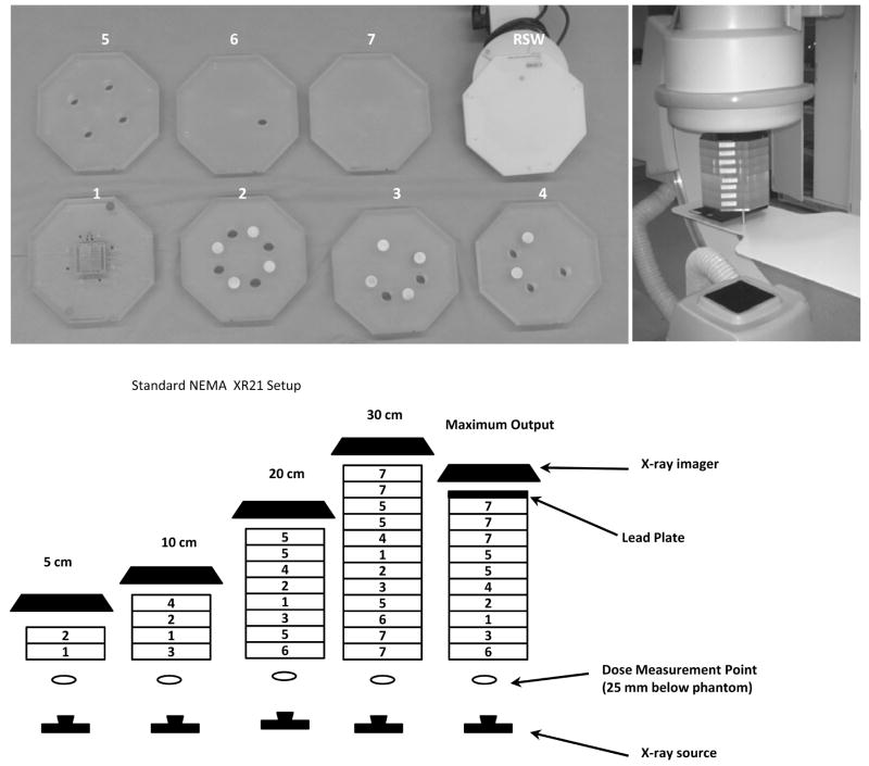
The NEMA XR21-20001 phantom (Figures 1 and 2) was originally designed for evaluating cardiac imaging units, but is not generally useful for all angiographic sytems.2–4 Various features such as bar patterns, iodine test-objects, and moving wires are included for the measurement of specific detector characteristics such as resolution, low contrast detectability, dynamic range and lag. Additional features are already present in a vascular phantom made by Nuclear Associates (now Fluke Biomedical, Model 76–710) (see Figures 3(d) and (e)) which follows AAPM report 15 recommendations.5 This phantom allows DA and DSA testing using simulated vessels, but does not have rotating spokes for temporal averaging evaluation, contrast-detail features, or features for working thickness range determination that are found in the NEMA phantom.
Figure 1.
Standard NEMA XR-21 phantom. Top left shows individual plates of the phantom; light circles on the plates are the aluminum cylinders; darker circles are holes passing through the entire plate. RSW stands for rotating spoke wheel. Top right shows the experimental setup. The 20 cm size phantom is placed in the field of view. The x-ray source is under the table. In the lower pictures, there are different configurations of the phantom to account for various situations, such as extremities, child thorax, adult thorax, large adult thorax, and x-ray maximum output. The plate numbers correspond to the numbers in the NEMA standard, and the plate types are shown in the top-left picture
Figure 2.
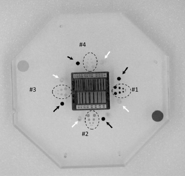
Details of the central plate of the NEMA XR-21 phantom. In the middle bar pattern, white arrows indicate the locations of the air pins, black arrows indicate the locations of the lead pins. The dotted circles indicate the position of the iodine contrast-detail target.
Figure 3.
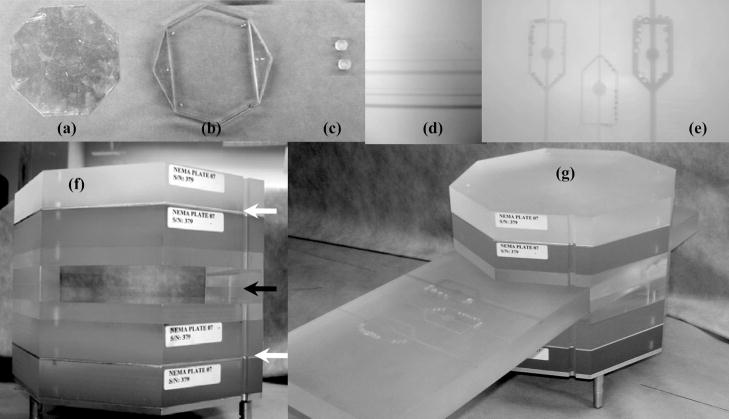
Components and overview of the modified NEMA XR 21-2000 phantom: (a) aluminum plate, (b) custom slot fixture built to allow vessel block insertion in the field of view, (c) plugs for the air cylinders (d) Low contrast artery block 76–715, (e) 15 mg/ml Stenosis/Aneurysm Artery Block- 76–705, (f) phantom containing new inserts, the white arrows indicate aluminum plate positions, the black arrow indicates the slot fixture for the subtraction blocks, (g) modified NEMA phantom with a low contrast vessel subtraction block placed in the slot.
We demonstrate here how, with only a few modifications to the NEMA phantom, we can expand the application of this phantom to vascular interventional systems other than cardiac. Such modifications include the addition of material to simulate the presence of bone and a fixture to enable use of vessel phantom inserts for testing subtraction techniques such as fluoroscopic roadmap and digital subtraction angiography.
Materials and methods
Phantom modification and testing procedures
A standard NEMA XR21-20001 phantom for testing cardiac units was modified by adding new components needed to evaluate an x-ray unit used in neuro and other vascular interventions. The standard phantom consists of 12 octagonal PMMA plates with thickness of 2.5 cm each. The plates can be arranged in different configurations in order to simulate different patient thicknesses Figure 1. The central plate (Figure 2) contains a resolution bar pattern, four iodine contrast-detail (C–D) targets, four air test pin cylinders and a lead test pin.
There are 4 sets of iodine C-d targets each containing four pairs of holes with diameters of 4, 3, 2, and 1 mm. Each set has different iodine areal densities of iodine imbedded in epoxy: 20, 10, 5 and 2.5 mg/cm2 The air test pins are placed within 4 air cylinders made in the PMMA plates. By arranging the plates appropriately in the 20 cm configuration, the air pins are superimposed cylinders with air thickness of 175, 150, 125 and 100 mm, respectively. The 4 lead pins are superimposed over the aluminum cylinders placed in NEMA plates. The thicknesses of the 4 aluminum cylinders are 40, 47, 53 and 60 mm, respectively. The rest of the thickness up to 200 mm is made from PMMA.
A rotating disk (see Fig 1, top left RSW) replaces the central test plate at iso-center to allow visual evaluation of motion unsharpness and the effects of temporal averaging. The device contains five steel wires of different diameters (0.56, 0.41, 0.30, 0.23, 0.13 mm). Two lead dots are used to evaluate lag and recursive filtering. The rotation speed is 30 revolutions/min.
We modified the NEMA X-21 phantom as indicated in Figure 3 for evaluation of a C-arm system applied to neuro-vascular procedures by adding two aluminum plates to 15 cm of Plexiglas in order to simulate the x-ray attenuation of the human head. For our experimental setup, we chose the same thickness plates of 1.5 mm each. The two skull-bone-simulating aluminum plates (Figure 3(f)) black arrows) were machined to fit the NEMA phantom and placed under 2.5 cm of Plexiglas on each side of the phantom as suggested by AAPM Reports 31 and 60.6, 7
To test subtraction techniques, a special slot fixture was created (Figure 3(b) and (f) black arrow). Two half-inch base plates were cut to fit the phantom octagonal pattern and two triangular plates were also cut to fit two sides of the octagonal pattern and glued onto the base plates. When coupled together as shown in figure 2(c), they create a slot which allows facile movement of one-inch thick and 6 inch(~15cm) wide Plexiglas blocks containing iodine vessels.
Two simulated artery blocks were used in this experiment. The first one is a Nuclear Associates (Fluke Biomedical), Stenosis/Aneurysm Artery Block 76–705 as depicted in Figure 2(d). It is a 15 × 45 × 2.5 cm piece that contains three iodine-filled simulated arteries whose width and depth are 1, 2 and 4 mm. Each artery includes simulated stenoses and aneurysms that are one-fourth, one-half, and three-fourths of the individual artery’s width. The iodine concentration is 15 mg/ml. The module also has three cylinders of 1 cm diameter, each with different iodine content (1.5, 3 and 6 mg/cm2) for testing linearity. The second block is a Low-contrast Artery Insert 76–715 by Nuclear Associates which contains iodine-filled channels simulating three sets of vessels (0.5, 1, 2 and 4 mm diameter). Each set has a different iodine concentration 2.5, 5 and 10 mg/cm3.
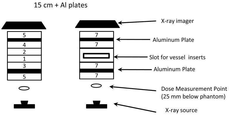
In Figure 4, we show the NEMA phantom modified with the addition of bone simulating aluminum plates. There are two configurations: 15 cm Plexiglas with Al plates to replicate the recommended AAPM head-equivalent phantom (Report 31) with and without the addition of a slot fixture for vessel inserts and for verifying subtraction techniques.
Figure 4.
Modified NEMA XR-21 setup: the 15 cm configuration with aluminum plates to simulate bone corresponds to the head-equivalent phantom; placement of the slot fixture for vessel inserts as shown on the right maintains the total 15 cm thickness.
X-ray equipment testing
An Infinix Flat Panel (Toshiba Medical Systems, Tustin, CA) C-Arm unit was used for testing with the standard and the modified phantom. Static features such as the line pairs, iodine contrast-detail targets, and dynamic working range were all evaluated for the two phantom configurations. Moving wires were also evaluated. Images were evaluated post-acquisition; the window and level were changed in order to emphasize different features of the central plate.
Subtraction techniques, such as DSA and fluoroscopic Road Mapping, and standard Digital Angiography (DA), were verified using the central vessel-insert slot shown in Figure 2(a), white arrow. Features of the phantom such as simulated arteries, stenoses and aneurysms were noted on the x-ray images.
We selected standard angiographic procedure protocols set on the system with the default frame rate being 15 frames per second in fluoroscopy and 7.5 frames per second in DA and DSA when static features were imaged. For the moving wires test, we used the 30 frames per second technique. We chose the highest resolution for both systems, which corresponded to approximately a five-inch field of view.
Results
Standard NEMA XR21
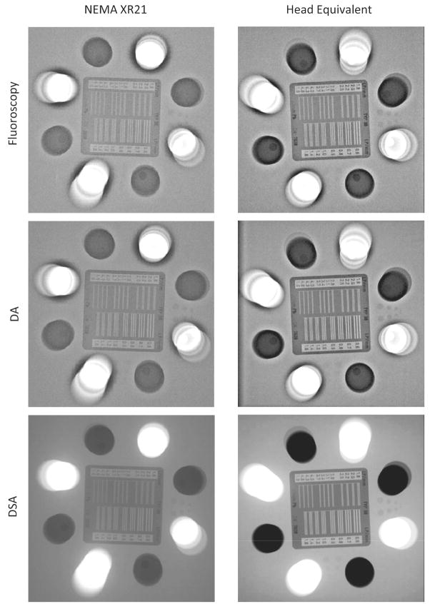
The standard 20 cm phantom was imaged with the Flat Panel (FP) C-Arm mounted x-ray detector as indicated in Figure 2, and the results are given in Table 1. Figure 5 shows images obtained for the stationary phantom for the three imaging modes. The bar pattern image showed 2.8 line-pairs/mm in fluoroscopy and 3.1 line-pairs/mm in DA and DSA techniques. For the iodine contrast-detail targets (Iodine C-d target’s) (Figure 2, dotted circles), the 4th target containing the lowest contrast concentration was not visible for any of the x-ray imaging techniques. The 3rd target was only partially visible in the DSA and not visible in DA or fluoroscopy. The 2nd target was fully visible in the DSA and partially in DA and fluoroscopy. The 1st target was fully visible in DA and DSA, but only partially in fluoroscopy. The working thickness analysis showed that the lead pins within the aluminum cylinders were always visible in all the imaging modes. The air pins superimposed on the air cylinders were only partially visible. Two of the 4 were visible in the fluoroscopy and the DA and only one in the DSA images due to saturation of the detector pixel located over the cylinders.
Table 1.
Results of the Standard NEMA measurements and Head Equivalent measurements
| Fluoroscopy | DA | DSA | |||||
|---|---|---|---|---|---|---|---|
| Std | Head Eq. | Std | Head Eq | Std | Head Eq. | ||
| Static features | Bar pattern | 2.8 | 3.1 | 3.1 | 3.1 | 3.1 | 3.1 |
| Iodine C-d target 1 | 6/8 | 8/8 | 8/8 | 8/8 | 8/8 | 8/8 | |
| Iodine C-d target 2 | 6/8 | 6/8 | 6/8 | 6/8 | 8/8 | 8/8 | |
| Iodine C-d target 3 | 0/8 | 0/8 | 0/8 | 0/8 | 4/8 | 2/8 | |
| Iodine C-d target 4 | 0/8 | 0/8 | 0/8 | 0/8 | 0/8 | 0/8 | |
| Air cylinders + air Pins | 2/4 | 3/4 | 2/4 | 3/4 | 1/4 | 0/4 | |
| Al cylinders + Pb Pins | 4/4 | 4/4 | 4/4 | 4/4 | 4/4 | 4/4 | |
|
| |||||||
| X-ray parameters | kVp | 80 | 80 | 73 | 74 | 80 | 96 |
| Tube Current (mA) | 32 | 37 | 269 | 342 | 160 | 125 | |
| Frame Exposure (ms) | 9.3 | 7.4 | 5.1 | 4.1 | 71.1 | 50 | |
| EEphantom (mR/frame) | .988 | 0.760 | 14.12 | 10.28 | 97.2 | 74.4 | |
| EEDetector (mR/frame) | 0.011 | 0.033 | 0.136 | 0.231 | 1.15 | 2.28 | |
|
| |||||||
| Moving features | Moving wires | 2/5 | 4/5 | 4/5 | 5/5 | 4/5 | 5/5 |
| Temporal Filtering | 4 | 4 | None | None | None | None | |
|
| |||||||
| X-ray parameters | kVp | 80 | 80 | 73 | 80 | 93 | 94 |
| Tube Current (mA) | 28 | 29 | 231 | 200 | 320 | 320 | |
| Frame Exposure (ms) | 5.6 | 4.5 | 4.1 | 5.9 | 16 | 14.3 | |
| EEphantom (mR/frame) | .435 | 0.615 | 7.88 | 7.47 | 45 | 60 | |
| EEDetector (mR/frame) | .012 | 0.028 | 0.098 | 0.191 | 1.456 | 2.24 | |
Figure 5.
FP snapshots of the standard 20 cm NEMA XR-21 phantom are shown in the left column, while those for the 15 cm phantom modified by addition of the aluminum filtration are shown in the right column. The top row is acquired using fluoroscopy, middle row Digital Angiography (DA) and the bottom row is acquired using Digital Subtraction Angiography (DSA). (The actual resolution for the bar pattern is not viewable due to reproduction degradation of the images).
Moving features imaging with the FP showed only two of the wires visible in the fluoroscopy, and four out of five visible in the DA and DSA. Snapshots of the lead dots of the rotating wheel showed four positions from the previous frames. There was no observable signal from the previous frames in any of the DA and DSA runs.
NEMA XR21-Head Equivalent
The head equivalent phantom was arranged according to the diagram in Figure 4. For the aluminum plates we used two plates with the same thickness 1.5 mm. The imaging results are shown in Table 1. For the bar pattern, 3.1 line-pairs/mm were visible in both DA and DSA. Iodine C-d target’s generally showed an improvement in the iodine targets visibility for DA and DSA compared to the Standard NEMA cardiac phantom. Iodine C-d target 1 was fully detectible in three modes; iodine C-d target 2 was partially detectible in fluoroscopy and DA and fully detectible in DSA; iodine C-d target 3 was partially detectible only in DSA. Visible air pins for fluoroscopy, DA and DSA were three, three and zero (due to saturation), respectively. All lead pins were visible in all three imaging modalities. Moving-features visualization with the FP using the modified phantom was better with all 5 wires being visible in DA and DSA.
Vascular phantom x-ray imaging
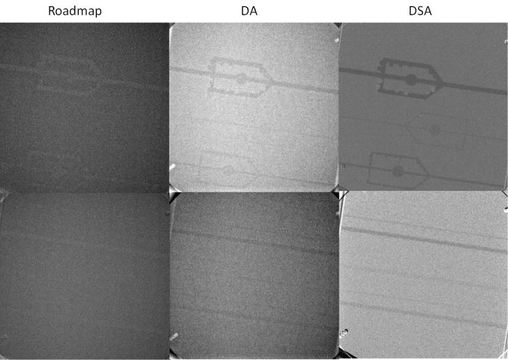
Figure 6 shows images obtained with the addition of the simulated vessel inserts. The results obtained using 15 cm PMMA + Al plates phantoms are presented in Table 2. The upper part of the tables contains an evaluation of the Stenosis/Aneurysms artery block and the lower part contains data for the low contrast artery insert.
Figure 6.
The results acquired using x-ray imaging of the 15 cm (head-equivalent) phantom containing the 15 mg/cm3 Stenosis/Aneurysm Artery Block 76–705 (top line) and the Low-contrast Artery Insert 76–715 (bottom line) using RoadMap in the first column, Digital Angiograph (DA) middle column, and Digital Subtraction Angiography (DSA) third column
Table 2.
Vessel inserts 15 cm configuration
| RoadMap | Digital Angiography | DSA | |||||||||||
|---|---|---|---|---|---|---|---|---|---|---|---|---|---|
|
|
|||||||||||||
| 4mm | 2mm | 1mm | 4mm | 2mm | 1mm | 4mm | 2mm | 1mm | |||||
|
|
|||||||||||||
| 15 mg/ml Stenosis/Aneurysm Artery Block- 76–705 | Vessel | 1/1 | 1/1 | 0/1 | 1/1 | 1/1 | 1/1 | 1/1 | 1/1 | 1/1 | |||
| Stenosis | 5/6 | 1/12 | 0/12 | 6/6 | 3/12 | 0/12 | 6/6 | 9/12 | 0/12 | ||||
| Aneurysms | 4/7 | 2/12 | 0/12 | 7/7 | 2/12 | 0/12 | 7/7 | 12/12 | 0/12 | ||||
|
| |||||||||||||
| Low-contrast Artery Insert 76–715 | 4mm | 2mm | 1mm | 0.5 mm | 4mm | 2mm | 1mm | 0.5 mm | 4mm | 2mm | 1mm | 0.5 mm | |
|
|
|||||||||||||
| 10 mg/cc | 1/1 | 1/1 | 0/1 | 0/1 | 1/1 | 1/1 | 0/1 | 0/1 | 1/1 | 1/1 | 1/1 | 0/1 | |
| 5 mg/cc | 1/1 | 0/1 | 0/1 | 0/1 | 1/1 | 0/1 | 0/1 | 0/1 | 1/1 | 1/1 | 0/1 | 0/1 | |
| 2.5 mg/cc | 0/1 | 0/1 | 0/1 | 0/1 | 1/1 | 0/1 | 0/1 | 0/1 | 0/1 | 1/1 | 0/1 | 0/1 | |
|
| |||||||||||||
| X-ray Parameters | kVp | 80 | 73 | 93 | |||||||||
| Tube Current (mA) | 34 | 297 | 125 | ||||||||||
| Exposure (ms) | 6.1 | 3.6 | 45.4 | ||||||||||
| EEPhantmo (mR/frame) | 0.77 | 10.7 | 76.7 | ||||||||||
| EEDetector (mR/frame) | 0.0312 | 0.243 | 2.61 | ||||||||||
In the x-ray images of the stenosis/aneurysm block for the Head equivalent configuration, the 4 and 3 mm arteries were visible with all imaging modes; however the 1 mm artery was detectable only in DA and DSA. For the fluoroscopic imaging, the simulated stenoses were visible only for the 4 mm artery block. Finer features were not visible: one stenosis and 3 aneurysms were not detectible on the acquired images. DA and DSA techniques performed much better; features were fully detectable for the 4 mm artery. For the 2 mm artery, only larger features were visible in DA, while for the 1 mm vessel no aneurysms or stenoses could be identified. DSA was better in that all the aneurysms were visible for the 2 mm vessels; however, four stenoses could not be seen. On the 1 mm artery, only one aneurysm was detected but no stenoses.
The low-contrast block analysis showed that for a density larger than 5 mg/cc of iodine, any vessel larger than 2 mm can be visualized in any imaging mode in both phantoms. For 2.5 mg/cc, 4 mm vessels can be detected in DA, and vessel larger than 2 mm can be detected in DSA. Vessels smaller than 1 mm cannot be detected in any imaging mode if an iodine concentration less than or equal to 10 mg/cc is used.
Discussion
We present a modification of the standard NEMA XR21 cardiac phantom. The new features increase the range of x-ray imaging systems and techniques that can be tested using a single modified phantom. The additions are very straightforward and can be done relatively easily. The phantom objects used for evaluating subtracted x-ray imaging techniques are commercially available, and they can be easily inserted within the middle of the octagonal NEMA phantom plates using a simple a slot fixture described here.
As we have shown, the new phantom can be readily used to evaluate x-ray machine physical parameters such as resolution, low contrast detectability, working thickness range, moving-objects detectability, lag and temporal filtering effects.
Adapting the phantom for the specific imaging task is very important as shown by the examples of its application presented in this paper. The changes we observed in the working thickness were mixed, but can be attributed to a combination of x-ray parameter changes as well as to the increased attenuation by the aluminum in the area of the air cylinders. Air pin detection was severely affected by the saturation of the detector pixel in the area overlapping the air cylinders. Overall, the x-ray parameters changed after the addition of the aluminum plates increasing the input exposure to the patient; however, the x-ray input to the detector behaved differently among the imaging modalities. For fluoroscopy, the detector input exposure increased, while for DA and DSA it decreased.
The addition of the hollow slot fixture allows verification of subtraction techniques. In our example, we evaluated two standard blocks with simulated arteries recommended by the AAPM report Task Group 4.5 This feature can be used not only for establishing system performance, but also for optimization of the x-ray parameters for specific object detection.
For convenience we acquired the data using two plates of the same thickness 1.5 mm. However, by choosing specific aluminum plate and PMMA thicknesses, different AAPM or CDRH standard phantoms7 can be constructed. The slot fixture additionally provides the capability to combine subtraction and low contrast feature imaging with any of the standard phantoms.
The phantom shown in this paper is appropriate to a variety of body parts to be imaged with an x-ray system. It can be adapted easily to test cardiac, neurologic and extremity x-ray imaging systems. It includes standard methods of evaluation, and it contains features specific to image-guided endovascular and vascular diagnostic procedures. Many of these features are available on different phantoms. However, the modifications we made to the NEMA XR21 phantom enables this standard phantom to be more generally extended in applicability to a larger number of systems including newer high resolution micro-angiographic systems presently under development8–10.
Conclusions
An important step in the research, development, and routine quality assurance for vascular imaging equipment is the selection of a somewhat standard phantom for evaluating this equipment. The new additions to the NEMA XR21-2000 cardiac phantom reported here extends this standard phantom’s applicability to the testing of units used in neuro- and general- as well as in cardio- vascular procedures. The new features are cost and materials effective through the combination of available test objects and allow multiple task-oriented evaluation of the x-ray units used during endovascular image-guided interventions.
Acknowledgments
NIH Grants R01-NS43924, R01-EB002873, R01-EB008425 and Toshiba Medical Systems Corporation.
References
- 1.National Electrical Manufacturer’s Association, [Characteristics of and test procedures for a phantom to benchmark cardiac fluoroscopic and fluorographic performance], NEMA Standards Publication XR 21, Rosslyn VA, (2000).
- 2.Balter S. A new tool for benchmarking cardiovascular fluoroscopes. Catheterization and Cardiovascular Interventions. 2001;52:67–72. doi: 10.1002/1522-726x(200101)52:1<67::aid-ccd1016>3.0.co;2-l. [DOI] [PubMed] [Google Scholar]
- 3.Lin P. A comprehensive quality assurance phantom for cardiovascular imaging systems. Proc SPIE. 1998;3336:752–760. [Google Scholar]
- 4.Bednarek DR, Rudin S, Yadava G, Dohatcu A. Composite Fluorographic System Evaluation. Med Phys. 2005;32(6):2123. [Google Scholar]
- 5.Report of Digital Radiography/Fluorography Task Group, Diagnostic X-ray Imaging Committee, [Performance Evaluation and Quality Assurance in Digital Subtraction Angiography, AAPM Report No. 15], Medical Physics Publishing, Madison, WI, (1985).
- 6.Report of Task Group 8, Diagnostic X-ray Imaging Committee, [Standardized Methods for Measuring Diagnostic X-Ray Exposures, AAPM Report No. 31], Medical Physics Publishing, Madison, WI, (1990).
- 7.Report of Task Group 4, Diagnostic X-ray Imaging Committee, [Instrumentation Requirements of Diagnostic Radiological Physicists (Generic Listing), AAPM Report No. 60], Medical Physics Publishing, Madison, WI, (1998).
- 8.Ionita CN, Patel V, Keleshis C, Bednarek DR, Hoffmann KR, Rudin S. Update on the development of a new dual detector (micro-angiographic fluoroscope/flat panel) c-arm mounted system for endovascular image guided interventions (EIGI) Med Phys. 2008;35:2870. [Google Scholar]
- 9.Ionita CN, Keleshis C, Patel V, Yadava G, Hoffmann KR, Bednarek DR, Jain A, Rudin S. Implementation of a high-sensitivity micro-angiographic fluoroscope (HS-MAF) for in-vivo endovascular image guided interventions (EIGI) and region-of-interest computed tomography (ROI-CT) Med Phys. 2008;6918:69181I. doi: 10.1117/12.770297. [DOI] [PMC free article] [PubMed] [Google Scholar]
- 10.Rudin S, Kuhls A, Keleshis C, Kim D, Yadava G, Patel V, Ionita CN, Hamwi H, Cartwright A, Verevkin A, Hoffmann KR, Bednarek DR. The solid state x-ray image intensifier (SSXII): A next-generation high-resolution fluoroscopic detector system. Med Phys. 2007;34:2585. [Google Scholar]


