Abstract
Inorganic–organic hybrid materials designed to facilitate bone tissue regeneration use a calcium phosphate mineral layer to encourage cell adhesion, proliferation, and osteogenic differentiation. Mineral formed on porous materials is often discontinuous through the thickness of the scaffold. This study aimed to uniformly coat the pores of three-dimensional (3D) porous, polymer scaffolds with a bone-like mineral layer in addition to uniformly incorporating a model protein within this mineral layer. A filtration system designed to induce simulated body fluid flow through the interstices of 3D polylactic-co-glycolic acid scaffolds (10-mm diameter × 2-mm thickness) illustrated that a uniform, continuous mineral layer can be precipitated on the pore surfaces of a 3D porous structure within 5 days. MicroCT analysis showed increased mineral volume percent (MV%) (7.86 ± 3.25 MV%, p = 0.029) and continuous mineralization of filtered scaffolds compared with two static control groups (floating, 0.16 ± 0.26 MV% and submerged, 0.20 ± 0.01 MV%). Furthermore, the system was effective in coprecipitating a model protein, bone sialoprotein (BSA), within the mineral layer. A 10-fold increase in BSA incorporation was seen when coprecipitated filtered scaffolds (1308 ± 464 μg) were compared to a submerged static control group (139 ± 45 μg), p < 0.001. Confocal microscopy visually confirmed uniform coprecipitation of BSA throughout the thickness of the filtration scaffolds. The designed system enables 3D mineralization through the thickness of porous materials, and provides the option of including coprecipitated biomolecular cues within the mineral layer. This approach of providing a 3D conductive and osteoinductive environment could be conducive to bone tissue regeneration.
Keywords: bioreactor, mineral-protein coprecipitation, bone-like mineral, three-dimensional, biomineralization
INTRODUCTION
The restoration and repair of orofacial and long-bone defects resulting from disease, trauma, or genetic inheritance is still a major clinical challenge.1–4 Autogenous bone grafting is a current method used in repairing skeletal defects. However, limitations including donor site morbidity, graft rejection, and inadequate bone formation or quality often result.2,5 Current approaches in bone tissue engineering strive to overcome these limitations and induce bone formation using a combination of an extracellular matrix analogue, cells, and/or biological signals.6–9
Three approaches are used in tissue engineering: conduction, induction, and cell transplantation.10,11 Initial research has focused on a conductive approach that aims to recruit host cells towards an implanted material and initiate bone ingrowth or regeneration. Research using inductive approaches of incorporating cell-recruiting or cell-directing molecules in or on the implant has increased to improve the rate, amount, and quality of bone being regenerated.12 In parallel, control of the location and direction of bone growth via transplantation of bone cell lines, genetically manipulated cells, or stem cells on these constructs has been explored.13 Cells are typically seeded on highly porous (>90%) scaffolds fabricated from biodegradable materials. To control cell responses, such as adhesion, the material can be modified via surface alterations or coatings.
Specific to bone scaffolding, strategies to increase the quantity and quality of regenerated bone include using organic/inorganic hybrid materials that promote bone healing and remodeling. For example, the technique of biomimetically precipitating a bone-like mineral layer onto porous polymer scaffolding provides cells a calcium phosphate material surface that is chemically similar to the composition of natural bone. This technique of biomimetically precipitating apatite onto the surface of a biomaterial was first researched on silica-rich Bioglass®14 and was subsequently introduced on titanium hip implants to enhance implant–bone osseointegration.15 Biomimetic deposition of bone-like mineral occurs at biological temperatures, making it an attractive alternative to high-temperature processing methods such as plasma spray and sputtering techniques.16,17 The biomimetic technique in bone tissue engineering has evolved into mineralizing biodegradable polymeric scaffolds with the intent of tailoring calcium phosphate ratios to evoke particular cell behavior while also increasing scaffold mechanical integrity.18 The presence of bone-like mineral is hypothesized to recruit host cells as well as to have the ability to control the differentiation of transplanted cells towards a bone phenotype.19
Surface pretreatments that create negatively charged surface groups to accelerate mineral nucleation benefit both 2D and 3D materials. While growth of bone-like mineral on polylactic-co-glycolic acid (PLGA) is attainable when a premineralization hydrolysis20 or aminolysis21 treatment is used, the apatite precipitated on 3D PLGA scaffolds is often discontinuous and can take up to 16 days to form.18,22 The lack of mineral continuity in 3D exists for both materials that do and do not receive surface pretreatments, supporting the need for innovations to improve current processing techniques. The design goals of using second-generation biomimetically mineralized materials therefore aim to reduce the time of apatite formation and to uniformly mineralize the interstices of 3D scaffolding, while controlling calcium phosphate ratios.23 To clarify terminology used, a dense substrate amenable to mineralization, such as a polymer or titanium surface is considered a 2D surface; however, when the substrate becomes porous and mineralization can occur through its thickness, the result is a 3D structure or scaffold.
In addition to a bone-like mineral layer providing a more conductive surface, the incorporation of inductive agents such as proteins or growth factors into the mineral can expose cells to spatiotemporally controlled biomolecular cues that can further promote and direct osteogenesis. Methods of incorporating proteins include covalent attachment, adsorption, and entrapment and are less than ideal for sustained release. A promising alternative to these methods is the coprecipitation of proteins and bone-like mineral. Depositing a protein–mineral layer on a porous scaffold provides a system that can deliver protein while allowing tissue ingrowth in 3D. Another advantage to coprecipitation is the ability to deposit bone-like mineral and proteins at physiological temperatures, minimizing potential processing parameters that could alter the biological activity of the incorporated biomolecules.24–26 A third advantage to coprecipitation is the ability to incorporate different biomolecules at different stages of mineral deposition, which provides a means of controlling release kinetics.19,27 Coprecipitation also leads to more sustained biomolecule release compared to adsorption, increases potential loading capacity, and is able to be used in conjunction with adsorption to further control biomolecular release.19,28 While coprecipitation is an effective means of incorporating biomolecules in bone-like mineral on dense, permanent implants, to be effective in tissue regeneration there is a need to rapidly and uniformly coat pores through the thickness of 3D scaffolding.
To study the effects of surface mineralization and biomolecular incorporation on bone growth in three dimensions, a scaffold uniformly and continuously coated with bone-like mineral or bone-like mineral with protein is necessary. Therefore, a filtration system was designed to induce flow of simulated body fluid (SBF), an ionic solution with similar ion concentrations as body serum, through the pores of polymer scaffolding to achieve mineralization throughout the thickness within 5 days. The goals of this study were to demonstrate: (1) the filtration system is capable of coating the pores of a 3D scaffold with a uniform, continuous bone-like mineral layer and (2) a model biomolecule, BSA, is capable of being incorporated throughout the 3D mineral layer. The hypothesis that flow of SBF through porous scaffolding will initiate mineralization within the pores of 3D scaffolds and induce the formation of a uniform mineral layer in 3D is tested. Furthermore, the capability of precipitating a continuous mineral–protein layer in 3D is also investigated. A combination of microcomputed tomography (MicroCT), X-ray diffraction (XRD), protein quantification, and confocal microscopy is used to illustrate uniform, continuous mineralization and protein incorporation throughout the thickness of 3D scaffolds.
MATERIALS AND METHODS
Scaffold Fabrication
The scaffolds were fabricated using a salt-leaching method. NaCl was sieved to 425–600 μm in diameter and packed into 10-mm diameter wells in a Delrin® (filtration group) or Teflon® (control groups) mold. A 5 wt % 85:15 PLGA (i.v. = 0.73 dL/g, Alkermes)–chloroform solution was added to each well. The scaffolds were covered with aluminum foil and dried under a chemical fume hood for at least 36 h. The mold was then placed in distilled water (dH2O) to leach out the salt particles for at least 36 h. The scaffolds were treated with 0.5M NaOH for 7 min and rinsed with dH2O. The final thickness of the scaffolds was approximately 2-mm.
SBF Preparation
Chemicals for making SBF were purchased from Sigma-Aldrich unless otherwise noted. The chemicals and concentrations used to make 1× SBF include 141 mM NaCl, 4.0 mM KCl, 0.5 mM MgSO4, 1.0 mM MgCl2, 4.2 mM NaHCO3, 5.0 mM CaCl2·2H2O, and 2.0 mM KH2PO4.29 To prepare 2× and 4× SBF, the concentrations were doubled and quadrupled, respectively. All SBF solutions were prepared at 25°C using dH2O. The 2× SBF was titrated to pH 6.8, and the 4× SBF was titrated to pH 6.4 using 1M NaOH. These pH values were used to avoid homogenous precipitation. Both 2× and 4× SBF were buffered with Tris–HCl. All SBF solutions were filtered using a 0.22-μm filter prior to use, and 0.005% sodium azide was added to prevent bacterial contamination.
Mineralization of Scaffolds in the Filtration System
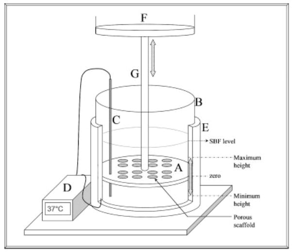
The Delrin® mold with salt-leached scaffolds (n = 4) was attached to the actuator of an Instron 8521 servohydraulic system and lowered into the aluminum base housing the SBF (Figure 1). The filtration system base is filled with SBF such that the scaffolds within the Delrin® mold are submerged with all surfaces being exposed to the SBF throughout the experiment. SBF solutions were warmed to 37°C prior to adding to the base. Initially, 1 L of 4× SBF (pH = 6.4) was used for 12 h, being replenished with fresh solution after 6 h. Subsequently, 1 L of 2× SBF (pH = 6.8) replaced the 4× SBF and was replenished every 12 h. The SBF was changed to sustain the appropriate ion concentration levels in addition to maintaining the pH of 6.4 or 6.8, which is conducive to heterogeneous precipitation of bone like mineral onto the scaffolds. The pH values of new (fresh SBF) and used (SBF being replenished) SBF were measured using a pH meter (Mettler Toledo MP230). A fatigue regimen was programmed on the Instron 8521 to cycle the mold with the scaffolds at an amplitude of 25.4 mm at 0.011 Hz for 5 days. A temperature controller (Extech Instruments, Model 48VTR) maintained a solution temperature of 37 ± 1°C. Two static control groups, submerged control (n = 4) and floating control (n = 4), were subjected to the same SBF regimen (0.5 L SBF instead of 1 L) in a 37°C incubator for 5 days. The submerged group scaffolds were prepared in a Teflon® mold. The scaffolds in the floating static group were cast in a Teflon® mold, removed, and mineralized in 50-mL conical tubes containing 50 mL of SBF. The 5-day mineralization experiment was repeated twice for all of the groups.
Figure 1.
Schematic showing the filtration device. The device consists of a Delrin® mold (A), aluminum base (B), thermocouple (C), temperature controller (D), and heating element (E). The Delrin® mold is connected to the actuator of an Instron 8521 servohydraulic system (F) and cyclically loaded via an aluminum rod (G). The SBF level and maximum and minimum positions that the Delrin® mold is displaced to are labeled on the figure. Holes in the Delrin® mold that did not have a PLGA scaffold were plugged with rubber stoppers. 1 L of SBF solution is housed in the aluminum base during mineralization. The Delrin® mold can simultaneously cast sixteen 10–mm diameter scaffolds (or twenty-five 5-mm diameter scaffolds, not shown).
BSA Coprecipitation
The Delrin® mold with salt-leached scaffolds (n = 8) was attached to the Instron 8521 system and lowered into the aluminum base housing the SBF or SBF:FITC–BSA. Fluoroisothiocyanate (FITC) conjugated BSA (Sigma-Aldrich, A9771) and BSA (Sigma-Aldrich, A3294) were used to prepare SBF:FITC–BSA solutions with a 1:5 ratio of FITC–BSA to BSA for a total protein concentration of 200 μg/mL. The SBF for these solutions was filtered using a 0.22-μm filter prior to the addition of FITC–BSA or BSA. Initially, 1 L of 4× SBF (pH = 6.4) was used for 12 h, being replenished with fresh solution after 6 h. Subsequently, 1 L of 2× SBF:FITC–BSA (pH = 6.8) replaced the 4× SBF and was replenished every 12 h. The SBF:FITC–BSA was changed to sustain the appropriate ion concentration levels, to replenish the FITC–BSA supply, and to maintain a pH of 6.8. A fatigue regimen was programmed on the Instron 8521 to cycle the mold with the scaffolds at an amplitude of 25.4 mm at 0.011 Hz for a total of 3 days. The temperature controller maintained a solution temperature of 37 ± 1°C. A submerged static group (n = 8) was prepared in a Teflon® mold and subjected to the same SBF and SBF:FITC–BSA regimen in a 37°C incubator for 3 days. The floating control group was excluded from this experiment, because the MicroCT analysis for this group showed the least amount of mineral volume percent (MV%) in the previously described 5 day mineralization experiment. An equal volume of SBF was used for the control and experimental groups to maintain similar FITC–BSA concentrations. The coprecipitation experiment was repeated twice for both groups.
MicroCT Analysis of Mineralized Scaffolds
After 5 or 3 days of mineralization, all scaffolds were removed, rinsed in dH2O, and dried under a chemical fume hood. Scaffolds were scanned (n = 4 for 5-day mineralized scaffolds, n = 8 for 3-day coprecipitated mineralized scaffolds) in a MicroCT system (EVS MS8X-130, 16-μm voxel size) to obtain MV% and 3D rendered images (Micro-View®, GE Systems). MicroCT scans were obtained at 75 mA and 75 mV for 400 frames using an aluminum filter. All reconstructed images were rendered in MicroView® using the Isosurface tool at a threshold of 1000 with the smoothing filter on, and at a surface quality factor of 0.55. A MV% profile for each group (filtration, submerged control, and floating control) was calculated using a volumetric shrinkage program written in MATLAB. This program calculates the centroid of each scaffold from a user-defined region of interest volume in MicroView, and subsequently uses spline calculations to determine a 16.7% volume shrinkage from the original volume. Analysis of progressively smaller concentric volumes resulted in six different shells of equal volumes per scaffold. The term “innermost shell” refers to the innermost volume, which is cylindrical in shape. The other five volumes calculated were concentric cylindrical shells. The MV% was calculated for each shell to compare the mineral gradient within and between the scaffold groups.
XRD Analysis
XRD spectra were obtained using a Rigaku Miniflex X-ray diffractometer with a fixed incidence of 4.2°. A range of 10–90° was scanned using a step size of 0.1° and a scan rate of 1°/min. The top surface of all of the scaffolds was scanned, unless otherwise noted. The raw data of a representative sample were plotted for all groups to compare the different conditions, which included filtration 5 days (n = 2), filtration 3 days (n = 1), filtration 1 day (n = 1), submerged control (5 days, n = 2), and filtration control (5 days, n = 2). The filtration samples retrieved after 1, 3, and 5 days were analyzed to evaluate time-dependent changes in mineral. A blank PLGA scaffold was also scanned to detect background from the substrate material. To investigate if the mineral formed in the center of the filtration scaffolds was similar to the mineral formed on the surface, 5-day filtration scaffolds were transversely cut and analyzed (filtration center 5 days, n = 2). Hydroxyapatite (Sigma-Aldrich #289396) and 6 wt % carbonated apatite (generous gift from Dr. Mike Morris, University of Michigan) were scanned as standards.
FTIR Analysis
Characteristic peaks for apatite were detected using a Fourier Transform Infrared Spectrometer (Spectrum BX FTIR, Perkin Elmer). A 300:1 ratio of KBr to deposited mineral was used prepare a pellet and analyze the filtration, submerged control, and filtration control groups (n = 2). Spectra were recorded from 400 to 4000 cm−1 and baseline corrected.
BSA Quantification
The amount of BSA coprecipitated onto the scaffolds (n = 8) was detected using a UV spectrophotometer (SmartSpec 3000, BioRad). Each scaffold was demineralized in 10 mM HCl. An aliquot of the demineralization solution was measured at a wavelength of 494 nm to detect the FITC conjugated to the BSA. Concentrations of coprecipitated FITC–BSA were determined from a standard curve prepared with a 1:5 ratio of FITC–BSA to BSA. The calibration curve was constructed for the FITC–BSA:BSA solution using serial dilutions in 1× PBS. Protein densities were calculated using values for the amount of mineral precipitated from MicroCT analyses and the amount of BSA coprecipitated from the quantitative UV spectrophotometry.
Confocal Microscopy
A 1–2-mm thick center cross-section from protein incorporated scaffolds was cut to expose the 2-mm depth of the scaffolds (n = 4). Each section, rectangular in shape (10 mm × 2 mm × 1–2 mm), was sandwiched between a glass slide and glued cover slip and viewed using confocal microscopy (Nikon TE 3000 Inverted Microscope) at an excitation wavelength of 488 nm. A BioRad Radiance 2000 LaserSharp program was used to image 750 μm into the 1–2-mm section at 3-μm intervals under 10× magnification. The series of images was compiled in the LaserSharp program to yield images showing FITC–BSA incorporation throughout the 750 μm. Multiple images were obtained across each sample and were mosaic-tiled together. The center cross-sections from scaffolds mineralized via filtration (5-day mineralization using the previously described 4× SBF/2× SBF regimen) without fluorescent-labeled protein were also investigated to characterize any mineral autofluorescence.
Statistics
The effect of filtration on MV% was determined using a one-way analysis of variance (ANOVA) on ranks with Student–Newman–Keuls post hoc evaluation. Significant differences in MV% between the concentric volumes within each group were also determined using ANOVA on ranks. The effects of filtration on MV% and on FITC–BSA incorporation for the BSA scaffolds were determined using a Student’s t-test. Significance was defined as p < 0.05, and all statistics were calculated using SigmaStat v3.1.
RESULTS
Uniform, Continuous Mineral Precipitated Throughout the Depth of Filtered Scaffolds
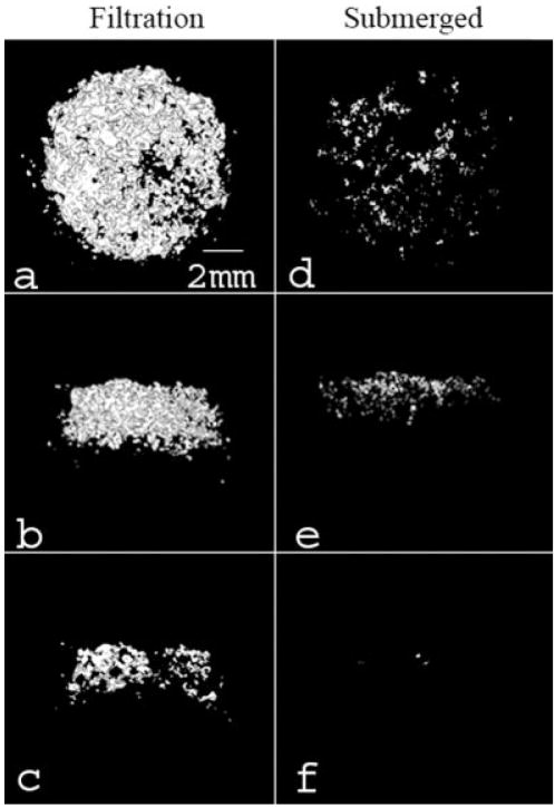
Filtration of SBF through the scaffold pores significantly increased the mineral deposition compared to both the submerged and floating static control groups (Figures 2 and 3). The qualitative 3D MicroCT renderings for the filtration and submerged control groups show increased mineral within the filtration group (Figure 2). The cross-section images [Figure 2(c,f)] also confirmed that mineral was present throughout the thickness of the filtration scaffolds. The floating control group 3D renderings did not show any mineralization (images not shown). The MV% in the filtration scaffolds was significantly greater than both control groups (floating control p = 0.029, submerged control p = 0.029). There was also an even distribution of mineral throughout the filtration scaffolds compared with both control groups, which had >60% of the precipitated mineral in the two outermost shell volumes (Figure 4). If the average amount of mineral precipitated (~8%, Figure 3) on the filtration scaffolds is combined with the initial amount of PLGA present (5%), the scaffold porosity would decrease, on average, from 95% to approximately 87% for the filtration scaffolds.
Figure 2.
Representative MicroCT images of the filtration group (a–c) and the submerged control group (d–f). These images represent top (a,d), side (b,e), and center cross-sections (c,f). A greater amount of mineral formed on the filtration scaffolds in comparison to the submerged control group. Renderings of the floating control group are not shown because mineral present in the images was minimal (<0.2 MV%). All images were created in MicroView® using the Isosurface tool (voxel size = 16 μm, threshold = 1000, surface quality factor = 0.55).
Figure 3.
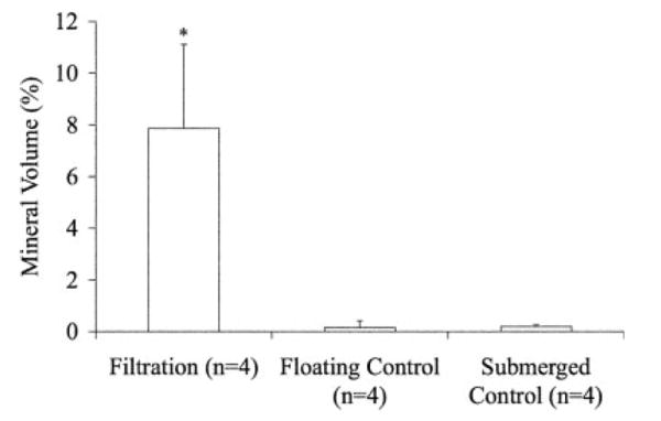
MV% for the filtration, floating control, and submerged control groups demonstrated the filtration group mineralized the greatest amount. (*p = 0.029 vs. both controls). MV% was calculated from MicroCT data using MicroView® at a threshold of 1000.
Figure 4.
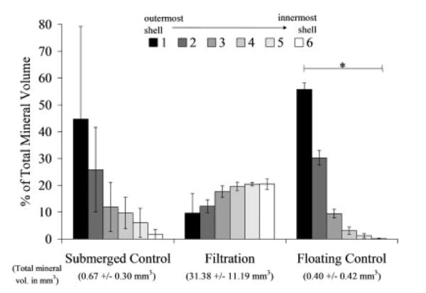
Volumetric mineral analysis of the MicroCT images (threshold = 1000) showing the filtration scaffolds have a uniform mineral profile throughout all six regions of the scaffolds analyzed. The MV% for 6 concentric shell volumes show the control mineralized scaffolds have at minimum 60% of the mineral present in the 2 outer shells (shells 1 and 2). The floating control group shell volumes were statistically different from one another (n = 4, p = 0.002), whereas the submerged control and filtration groups did not show significance (n = 3, p = 0.051 and n = 4, p = 0.104, respectively). *Statistical significance found, p < 0.050.
The mineral deposited on the scaffolds showed characteristic FITR peaks for both hydroxyapatite (ν3c P–O 1032 cm−1, ν1 P–O 962 cm−1, ν4a O–P–O 602 cm−1, and ν4c O–P–O 561 cm−1 [filtration group only]) and carbonated apatite ( 1465 cm−1 [filtration and floating control groups])30 (Figure 5). XRD spectra for all of the groups also show apatite characteristic 2θ peaks between 25.9° and 26.8°, between 31.8° and 32.7°, at 40.1°, and between 45° and 55° (Figure 6).30 The XRD spectra further reveal that the peaks from the filtration scaffolds are consistent over the 5 days of mineralization, providing evidence that the mineral being precipitated on days 1 and 3 is similar to the mineral being precipitated on day 5. Last, XRD analysis confirms that the type of mineral deposited was similar in all three experimental groups (filtration, submerged control, and floating control).
Figure 5.
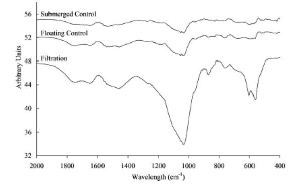
FTIR spectra for filtration, floating control, and submerged control groups showing the mineral deposited on the scaffolds was characteristic of hydroxyapatite with carbonate peaks (ν3c P–O 1032 cm−1, ν1 P–O 962 cm −1 ν4a O–P–O 602 cm−1, and ν4c O–P–O 561 cm−1 [filtration group only]) and carbonated apatite ( 1465 cm−1 [filtration and floating control groups]). Stronger peaks for the filtration group indicate the presence of more mineral.
Figure 6.
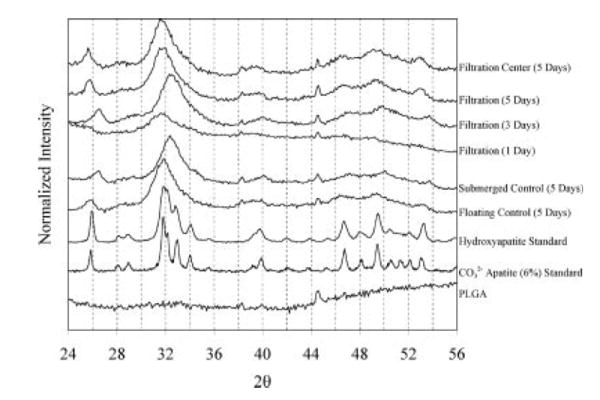
XRD spectra for all three groups (filtration, floating control, submerged control) show characteristic apatite peaks between 25.9° and 26.8°, between 31.8° and 32.7°, at 40.1°, and between 45° and 55° when compared to the hydroxyapatite standard. A similar type of mineral was precipitated over the 5 days of filtration (1, 3, and 5 days). To assess if the mineral formed within the center of the filtration scaffolds was similar to the mineral formed on the surface of the filtration scaffolds, 5-day scaffolds were sectioned transversely and analyzed (filtration center 5 days). The mineral formed on the interior surface of 5-day filtration scaffolds showed a similar spectrum to the mineral formed on the outer surface of the same scaffolds at 5 days, verifying that a similar mineral formed throughout the depth of the scaffold.
Uniform and Increased BSA Incorporation in Filtered Scaffolds
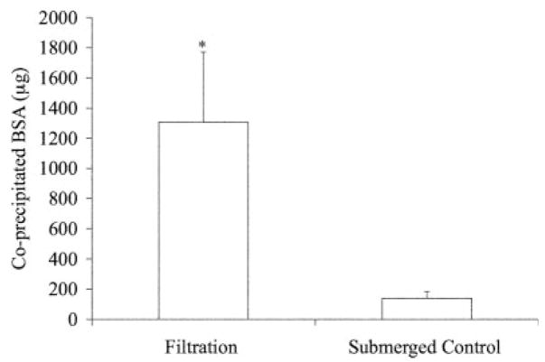
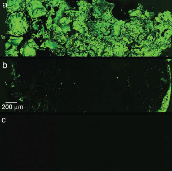
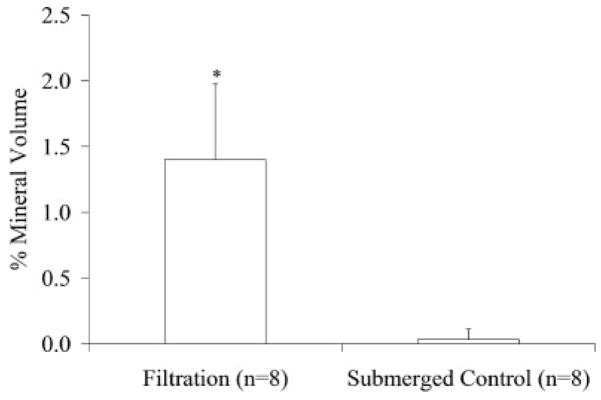
A 10-fold increase in protein incorporation (Figure 7) was established in the scaffolds mineralized using the filtration device. Confocal microscopy supported the increased protein incorporation within the filtration group, in addition to showing uniform precipitation throughout the thickness of the scaffolds (Figure 8). The confocal microscopy methods followed in these [Figure 8(c)] and other experiments revealed no interfering autofluorescence from the PLGA or the mineral.19 Similar to the 5-day filtration mineralized scaffolds, a greater amount of mineral was deposited on the 3-day coprecipitated filtration scaffolds compared to the static controls, p < 0.001 (Figure 9).
Figure 7.
Quantitative coprecipitated BSA values (μg) showing greater protein incorporation in the filtered scaffolds. The amount of BSA incorporated was quantified using UV Spectrophotometry at 494nm wavelength to detect the FITC–BSA. (*Statistically significant compared to submerged control group, p < 0.001).
Figure 8.
Representative confocal microscopy images of transverse sections of filtration (a) and submerged control (b) groups coprecipitated with BSA for 3 days. The mosaic images were compiled from multiple images of the center cross-section for each scaffold in each group (n = 4 per group). The incorporation of BSA is shown by the fluorescence of FITC conjugated to the BSA. The filtration scaffolds showed uniform BSA coprecipitation throughout. A typical mineral shell, evidenced by more FITC seen on the left and right edges, is seen for the submerged control group. The presence of a mineral shell also supports less BSA incorporation. Autofluorescence of the mineral was not detected, shown by a representative image of a center cross-section of a scaffold mineralized via filtration for 5 days using the 4× SBF/2× SBF regimen precipitated without protein (c). Original images were taken at 10×. [Color figure can be viewed in the online issue, which is available at www.interscience.wiley.com.]
Figure 9.
MV% for the filtration and submerged control coprecipitation groups demonstrated the filtration group mineralized the greatest amount (*p < 0.001). MV% was calculated from MicroCT data using MicroView® at a threshold of 1000.
DISCUSSION
Using the filtration system developed, a uniform 3D substrate surface that mimics the inorganic composition of bone was created, providing a microenvironment that could potentially enhance osteogenesis.31 Designing a biomaterial that can enhance the ability of cells to attach and proliferate is an imperative aspect of controlling cellular microenvironment. Seeding cells on 3D scaffolding as a first step in controlling cell function however, is not trivial.32 Nonuniform apatite coverage on scaffolding is preventative of uniform cell seeding. By establishing a technique that can consistently provide uniform and continuous mineral coverage of 3D porous scaffolding, it is hypothesized that cell seeding uniformity will be enhanced and uniform osteogenesis will be more likely to occur.
The precipitation of a continuous mineral film onto pore surfaces of the polymer substrate was the goal of the initial filtration experiment. Appropriate ion concentrations are necessary for calcium phosphate growth,33 particularly within the internal pores of a 3D scaffold. In order to maintain film formation, the thermodynamics of the SBF must be held below the homogenous precipitation limit and above the solute saturation limit.34 If these conditions are not met, then no or minimal mineral will form.20,34 To provide the pore surfaces within the interstices of the scaffolds appropriate ion concentrations for film formation to occur, the delivery method of SBF can be enhanced. Flow perfusion bioreactors have already shown that increased mass transfer in 3D is responsible for increases in cell numbers, resulting in uniform tissue growth.35 Additionally, the flow conditions and resulting shear stresses that occur within these bioreactors have been modeled.36 By facilitating flow of the SBF through the scaffold pores, an appropriate ion concentration was expected to occur within the interstices of the scaffolds allowing mineral to form throughout the thickness.
To further accelerate mineral nucleation on all pore surfaces, the PLGA polymer surface was treated with NaOH, facilitating alkaline hydrolysis that increases the number of free carboxylic acid groups on the surface. This treatment accelerates heterogeneous precipitation of a bone-like mineral by creating an environment where free carboxylic acid groups that can interact with ions in solution are formed at a greater rate than just by hydrolysis in SBF.20 The presence of negatively charged surface groups provides a substrate more capable of apatite nucleation compared to positively charged surfaces.37
The enhancements to the SBF delivery and more rapid functionalization of the polymer surface together indicate that an appropriate ion concentration was established within the filtration scaffolds. While both control scaffold groups were treated with NaOH, neither group showed continuous mineralization through the scaffold thickness, showing that the improvement to SBF delivery via flow is responsible for the continuous mineralization seen within the filtration scaffolds. Maintaining this appropriate ionic environment depends on temperature, pH, and the concentration of the solutes. Efforts to control the temperature and pH were enforced by the use of a temperature controller held at 37 ± 1°C and frequent replacement of the SBF solution. The pH values of both the new and used SBF were monitored every time the SBF was changed (every 6 h for 4× SBF and every 12 h for 2× SBF), and the filtration group had an average increase in pH of 0.47 ± 0.09, whereas the submerged group had an average increase of 0.37 ± 0.07. The pH changes reported are the maximum values that the pH had increased over a 12-h period and are likely to occur for a small percentage of each incubation period, because the SBF is replenished in a timely fashion. These pH changes keep the pH value of the solution between 6.4 and 6.8 when the scaffolds are submerged in 4× SBF and between 6.8 and 7.2 when the scaffolds are submerged in 2× SBF. The pH changes that occurred are thought to be greater than pH changes resulting solely from ion depletion, because the SBF in all groups is not completely sealed from the atmosphere nor titrated to maintain a constant pH.
Despite fluctuations in pH, the mineral precipitated in the filtration, submerged control, and floating control groups all show characteristic XRD peaks of carbonated apatite. The mineral formed at 1, 3, and 5 days using the filtration system is similar (Figure 6). The 1-day filtration spectrum had the lowest intensity above the background, suggesting that the mineral could be less crystalline than the mineral formed at later times. This indicates that a more amorphous apatite phase or a nanocrystalline phase could be forming during the first day of precipitation. This XRD spectrum after 1 day of mineralization is consistent with spectra of apatite precipitated on PLLA and PGA films after 24 h in a 5× SBF solution.38 Spatially, the mineral precipitated on the outer scaffold surface (filtration 5 days) showed similar peaks as the mineral precipitated within the center of the scaffold (filtration center 5 days), supporting the deposition of uniform mineral throughout the filtration scaffolds. Because most forms of calcium phosphate that differ by a few percent in carbonate substitution have overlapping peaks, it is difficult to discern the specific type of apatite or calcium phosphate being formed in these experiments from the XRD spectra. However, carbonated apatite characteristic peaks were detected for the filtration and floating control groups in FTIR analysis, providing evidence that a carbonated apatite is being precipitated onto the scaffolds. The decreased resolution of the precipitated bone-like apatite compared to the hydroxyapatite and carbonated apatite standards could result from either the precipitated mineral being crystalline but having nanometer-range crystal size or the precipitated mineral containing a large fraction of an amorphous phase.39 A slight peak shift to higher 2θ values was seen for the submerged control and filtration (3 days) samples compared to the rest of the samples, which could be indicative of chloride substitutions within the apatite being formed.30
A model protein, BSA, was successfully incorporated into the mineral layer within 3 days. A 10-fold increase of protein incorporation was found in the coprecipitated scaffolds via filtration compared to the submerged control scaffolds (Figure 7). More protein incorporation in the filtration coprecipitation group is attributed to increased mineral formation on these scaffolds (Figure 8). The amount of protein coprecipitated within the filtration and submerged control groups (1308 ± 464 and 139 ± 45 μg, respectively) are comparable to previous coprecipitation reports that incorporated biomolecules within mineral or polymeric materials.19,40,41 Additionally, the scaffolds coprecipitated via filtration displayed uniform protein incorporation throughout the scaffold thickness, whereas the scaffolds coprecipitated via submersion showed protein incorporation only on the outer surfaces (Figure 9). This uniform incorporation would allow uniform biomolecular release throughout the scaffold in an in vitro or in vivo setting.
The protein densities for the filtration and submerged control groups were 345 ± 164 and 1260 ± 410 μg/mm3, respectively. The increased density within the submerged control is likely attributed to a static mineralization that allowed the BSA to adsorb to the surface of the scaffold prior to mineralization, whereas in the filtration group fluid movement limited BSA adsorption. However, cells transplanted onto coprecipitated scaffolds could favor a lower protein loading density. Coprecipitated inorganic coatings have shown to be effective on a dense 3D materials,26,42,43 and spatial control of the organic constituents within the coating of a film has been achieved19; however, to our knowledge, this is the first investigation of coprecipitation of mineral with protein on a 3D porous template. The aim of using the filtration method is to spatially localize biomolecules that promote bone formation into a more effective bone engineered template.
When coating implant materials, such as titanium hip replacements, the 2D surface is coated with a thick mineral layer to ensure the coating is present on the implant after the surgery. However, the design strategy of coating the pores of a 3D scaffold for tissue engineering differs from coating a 2D surface, because a main objective of coating a 3D scaffold is to retain porosity. Therefore, current coating techniques would not be effective in uniformly coating all pore surfaces within a 3D scaffold with a thin mineral layer, demonstrating the need for a method to uniformly coat pore surfaces of 3D scaffolds without compromising porosity.
Techniques to precipitate a uniform, continuous calcium phosphate layer on porous polymer scaffolds via premineralization aminolysis or hydrolysis have not been able to establish a continuous mineral layer in a time effective manner. Even with longer precipitation times, the mineral layer is not continuous throughout the thickness. The result is a thicker layer of mineral around the periphery of the scaffold, which can lead to pore occlusion and compromise cell function. An increase in the volume fraction of regenerated bone occurs on statically mineralized PLGA scaffolds having a 250–425 μm pore size range, compared to PLGA controls.31 In the presented work, the scaffold pore size ranged from 425 to 600 μm, so, as an example, a 20-μm thick layer of mineral would decrease the pore size range to 405–580 μm, which is larger than the pore size reported by Kohn et al. but within an identified range for bone ingrowth.44 Ultimately, the presence of continuous bone-like mineral throughout the polymer scaffolds is expected to lead to more continuous in vivo osteogenesis.
Although the initial design of the system enables a batch of sixteen 10-mm diameter scaffolds, mineralization of twenty-five 5-mm diameter scaffolds has also proved feasible (data not shown). Moreover, this system is not limited to PLGA scaffolds. Any material capable of being constrained in the Delrin® mold can be used with scaffold diameter and thickness as variable parameters.
In summary, incorporating a bone-like apatite mineral layer on polymer scaffolds in an environment conducive to biomolecular incorporation has the potential to increase the ability of cell recognition, attachment, and regeneration in vivo. A filtration device designed to force SBF through the pores of scaffolds enabled a uniform, continuous bone-like mineral layer to form throughout, and uniform mineral coverage could be attained in only 4–5 days. Additionally, a model protein, BSA, was coprecipitated uniformly in the bone-like mineral layer throughout the thickness of the scaffolds. Scaffolds mineralized within the filtration device displayed an increase in MV% and in the amount of incorporated BSA via coprecipitation compared to static mineralization. This filtration system can potentially be used to incorporate cell-signaling biomolecules, such as growth factors or DNA, to promote in vivo osteogenesis, in addition to serving as a technology to develop conductive materials.
Acknowledgments
The authors would like to thank the University of Michigan Chemistry Machine Shop and the Orthopedic Research Lab Machine Shop for their craftsmanship, in addition to Dr. Scott Hollister for the generous use of the MicroCT. The authors would also like to thank Jeff Meganck for his MATLAB expertise, Ricky Rossello, Colleen Flanagan, and Mike Barker for their helpful advice.
Contract grant sponsor: NIH; contract grant numbers: R01 DE 013380, DE 015411
Contract grant sponsor: Tissue Engineering at Michigan; contract grant number: DE 07057
References
- 1.Wiesmann HP, Joos U, Meyer U. Biological and biophysical principles in extracorporal bone tissue engineering. Part II. Int J Oral Maxillofac Surg. 2004;33:523–530. doi: 10.1016/j.ijom.2004.04.005. [DOI] [PubMed] [Google Scholar]
- 2.Parikh SN. Bone graft substitutes in modern orthopedics. Orthopedics. 2002;25:1301–1309. 1310–1311. doi: 10.3928/0147-7447-20021101-27. [DOI] [PubMed] [Google Scholar]
- 3.Muschler GF, Midura RJ. Connective tissue progenitors: practical concepts for clinical applications. Clin Orthop Relat Res. 2002;395:66–80. doi: 10.1097/00003086-200202000-00008. [DOI] [PubMed] [Google Scholar]
- 4.Feinberg SE, Aghaloo TL, Cunningham LL., Jr Role of tissue engineering in oral and maxillofacial reconstruction: Findings of the 2005 AAOMS Research Summit. J Oral Maxillofac Surg. 2005;63:1418–1425. doi: 10.1016/j.joms.2005.07.004. [DOI] [PubMed] [Google Scholar]
- 5.Yaszemski MJ, Payne RG, Hayes WC, Langer R, Mikos AG. Evolution of bone transplantation: molecular, cellular and tissue strategies to engineer human bone. Biomaterials. 1996;17:175–185. doi: 10.1016/0142-9612(96)85762-0. [DOI] [PubMed] [Google Scholar]
- 6.Shin H, Jo S, Mikos AG. Biomimetic materials for tissue engineering. Biomaterials. 2003;24:4353–4364. doi: 10.1016/s0142-9612(03)00339-9. [DOI] [PubMed] [Google Scholar]
- 7.Garcia AJ, Reyes CD. Bio-adhesive surfaces to promote osteoblast differentiation and bone formation. J Dent Res. 2005;84:407–413. doi: 10.1177/154405910508400502. [DOI] [PubMed] [Google Scholar]
- 8.Maskarinec SA, Tirrell DA. Protein engineering approaches to biomaterials design. Curr Opin Biotechnol. 2005;16:422–426. doi: 10.1016/j.copbio.2005.06.009. [DOI] [PubMed] [Google Scholar]
- 9.Hubbell JA. Bioactive biomaterials. Curr Opin Biotechnol. 1999;10:123–129. doi: 10.1016/s0958-1669(99)80021-4. [DOI] [PubMed] [Google Scholar]
- 10.Alsberg E, Hill EE, Mooney DJ. Craniofacial tissue engineering. Crit Rev Oral Biol Med. 2001;12:64–75. doi: 10.1177/10454411010120010501. [DOI] [PubMed] [Google Scholar]
- 11.Hirano Y, Mooney DJ. Peptide and protein presenting materials for tissue engineering. Adv Mater. 2004;16:17–25. [Google Scholar]
- 12.Chen RR, Mooney DJ. Polymeric growth factor delivery strategies for tissue engineering. Pharm Res. 2003;20:1103–1112. doi: 10.1023/a:1025034925152. [DOI] [PubMed] [Google Scholar]
- 13.Rose FRAJ, Oreffo ROC. Bone tissue engineering: Hope vs hype. Biochem Biophys Res Commun. 2002;292:1–7. doi: 10.1006/bbrc.2002.6519. [DOI] [PubMed] [Google Scholar]
- 14.Ogino M, Ohuchi F, Hench LL. Compositional dependence of the formation of calcium phosphate films on bioglass. J Biomed Mater Res. 1980;14:55–64. doi: 10.1002/jbm.820140107. [DOI] [PubMed] [Google Scholar]
- 15.Abe Y, Kokubo T, Yamamuro T. Apatite coating on ceramics, metals and polymers utilizing a biological process. J Mater Sci Mater Med. 1990;1:233–238. [Google Scholar]
- 16.de Groot K, Wolke JG, Jansen JA. Calcium phosphate coatings for medical implants. Proc Inst Mech Eng [H] 1998;212:137–147. doi: 10.1243/0954411981533917. [DOI] [PubMed] [Google Scholar]
- 17.Habibovic P, Barrere F, van Blitterswijk CA, de Groot K, Layrolle P. Biomimetic hydroxyapatite coating on metal implants. J Am Ceram Soc. 2002;85:517–522. [Google Scholar]
- 18.Murphy WL, Kohn DH, Mooney DJ. Growth of continuous bonelike mineral within porous poly(lactide-co-glycolide) scaffolds in vitro. J Biomed Mater Res. 2000;50:50–58. doi: 10.1002/(sici)1097-4636(200004)50:1<50::aid-jbm8>3.0.co;2-f. [DOI] [PubMed] [Google Scholar]
- 19.Luong LN, Hong SI, Patel RJ, Outslay ME, Kohn DH. Spatial control of protein within biomimetically nucleated mineral. Biomaterials. 2006;27:1175–1186. doi: 10.1016/j.biomaterials.2005.07.043. [DOI] [PubMed] [Google Scholar]
- 20.Murphy WL, Mooney DJ. Bioinspired growth of crystalline carbonate apatite on biodegradable polymer substrata. J Am Chem Soc. 2002;124:1910–1917. doi: 10.1021/ja012433n. [DOI] [PubMed] [Google Scholar]
- 21.Croll TI, O’Connor AJ, Stevens GW, Cooper-White JJ. Controllable surface modification of poly(lactic-co-glycolic acid) (PLGA) by hydrolysis or aminolysis I: Physical, chemical, and theoretical aspects. Biomacromolecules. 2004;5:463–473. doi: 10.1021/bm0343040. [DOI] [PubMed] [Google Scholar]
- 22.Zhang R, Ma PX. Biomimetic polymer/apatite composite scaffolds for mineralized tissue engineering. Macromol Biosci. 2004;4:100–111. doi: 10.1002/mabi.200300017. [DOI] [PubMed] [Google Scholar]
- 23.Oliveira AL, Malafaya PB, Reis RL. Sodium silicate gel as a precursor for the in vitro nucleation and growth of a bone-like apatite coating in compact and porous polymeric structures. Biomaterials. 2003;24:2575–2584. doi: 10.1016/s0142-9612(03)00060-7. [DOI] [PubMed] [Google Scholar]
- 24.Wen HB, de Wijn JR, van Blitterswijk CA, de Groot K. Incorporation of bovine serum albumin in calcium phosphate coating on titanium. J Biomed Mater Res. 1999;46:245–252. doi: 10.1002/(sici)1097-4636(199908)46:2<245::aid-jbm14>3.0.co;2-a. [DOI] [PubMed] [Google Scholar]
- 25.Wen HB, Wolke JG, de Wijn JR, Liu Q, Cui FZ, de Groot K. Fast precipitation of calcium phosphate layers on titanium induced by simple chemical treatments. Biomaterials. 1997;18:1471–1478. doi: 10.1016/s0142-9612(97)82297-1. [DOI] [PubMed] [Google Scholar]
- 26.Liu Y, Hunziker EB, Layrolle P, De Bruijn JD, de Groot K. Bone morphogenetic protein 2 incorporated into biomimetic coatings retains its biological activity. Tissue Eng. 2004;10:101–108. doi: 10.1089/107632704322791745. [DOI] [PubMed] [Google Scholar]
- 27.Azevedo HS, Leonor IB, Alves CM, Reis RL. Incorporation of proteins and enzymes at different stages of the preparation of calcium phosphate coatings on a degradable substrate by a biomimetic methodology. Mater Sci Eng C Biomimetic Supramol Syst. 2005;25:169–179. [Google Scholar]
- 28.Liu Y, Layrolle P, de Bruijn J, van Blitterswijk C, de Groot K. Biomimetic coprecipitation of calcium phosphate and bovine serum albumin on titanium alloy. J Biomed Mater Res. 2001;57:327–335. doi: 10.1002/1097-4636(20011205)57:3<327::aid-jbm1175>3.0.co;2-j. [DOI] [PubMed] [Google Scholar]
- 29.Kokubo T. Apatite formation on organic polymers by a biomimetic process. Eur J Solid State Inorg Chem. 1995;32:819–827. [Google Scholar]
- 30.Koutsopoulos S. Synthesis and characterization of hydroxyapatite crystals: A review study on the analytical methods. J Biomed Mater Res. 2002;62:600–612. doi: 10.1002/jbm.10280. [DOI] [PubMed] [Google Scholar]
- 31.Kohn DH, Shin K, Hong SI, Jayasuriya AC, Leonova EV, Rossello RA, Krebsbach PH. Self-assembled mineral scaffolds as model systems for biomineralization and tissue engineering. Proceedings of the Eight International Conference on the Chemistry and Biology of Mineralized Tissues; 2005. pp. 216–219. [Google Scholar]
- 32.Toh YC, Ho ST, Zhou Y, Hutmacher DW, Yu H. Application of a polyelectrolyte complex coacervation method to improve seeding efficiency of bone marrow stromal cells in a 3D culture system. Biomaterials. 2005;26:4149–4160. doi: 10.1016/j.biomaterials.2004.10.033. [DOI] [PubMed] [Google Scholar]
- 33.Feng QL, Cui FZ, Wang H, Kim TN, Kim JO. Influence of solution conditions on deposition of calcium phosphate on titanium by NaOH-treatment. J Cryst Growth. 2000;210:735–740. [Google Scholar]
- 34.Bunker BC, Rieke PC, Tarasevich BJ, Campbell AA, Fryxell GE, Graff GL, Song L, Liu J, Virden JW, McVay GL. Ceramic thin-film formation on functionalized interfaces through biomimetic processing. Science. 1994;264:48–55. doi: 10.1126/science.264.5155.48. [DOI] [PubMed] [Google Scholar]
- 35.Bancroft GN, Sikavitsas VI, Mikos AG. Design of a flow perfusion bioreactor system for bone tissue-engineering applications. Tissue Eng. 2003;9:549–554. doi: 10.1089/107632703322066723. [DOI] [PubMed] [Google Scholar]
- 36.Porter B, Zauel R, Stockman H, Guldberg R, Fyhrie D. 3-D computational modeling of media flow through scaffolds in a perfusion bioreactor. J Biomech. 2005;38:543–549. doi: 10.1016/j.jbiomech.2004.04.011. [DOI] [PubMed] [Google Scholar]
- 37.Tanahashi M, Matsuda T. Surface functional group dependence on apatite formation on self-assembled monolayers in a simulated body fluid. J Biomed Mater Res. 1997;34:305–315. doi: 10.1002/(sici)1097-4636(19970305)34:3<305::aid-jbm5>3.0.co;2-o. [DOI] [PubMed] [Google Scholar]
- 38.Chen Y, Mak AF, Li J, Wang M, Shum AW. Formation of apatite on poly(alpha-hydroxy acid) in an accelerated biomimetic process. J Biomed Mater Res B Appl Biomater. 2005;73:68–76. doi: 10.1002/jbm.b.30178. [DOI] [PubMed] [Google Scholar]
- 39.Posner AS, Blumenthal NC, Betta F. Chemistry and structure of hydroxyapatites. In: Nriagu JO, Moore PB, editors. Phosphate Minerals. Berlin: Springer Verlag; 1984. p. 330. [Google Scholar]
- 40.Shea LD, Smiley E, Bonadio J, Mooney DJ. DNA delivery from polymer matrices for tissue engineering. Nat Biotechnol. 1999;17:551–554. doi: 10.1038/9853. [DOI] [PubMed] [Google Scholar]
- 41.Kim H, Kim HW, Suh H. Sustained release of ascorbate-2-phosphate and dexamethasone from porous PLGA scaffolds for bone tissue engineering using mesenchymal stem cells. Biomaterials. 2003;24:4671–4679. doi: 10.1016/s0142-9612(03)00358-2. [DOI] [PubMed] [Google Scholar]
- 42.Liu Y, de Groot K, Hunziker EB. BMP-2 liberated from biomimetic implant coatings induces and sustains direct ossification in an ectopic rat model. Bone. 2005;36:745–757. doi: 10.1016/j.bone.2005.02.005. [DOI] [PubMed] [Google Scholar]
- 43.Stigter M, de Groot K, Layrolle P. Incorporation of tobramycin into biomimetic hydroxyapatite coating on titanium. Biomaterials. 2002;23:4143–4153. doi: 10.1016/s0142-9612(02)00157-6. [DOI] [PubMed] [Google Scholar]
- 44.Hollister SJ, Lin CY, Saito E, Lin CY, Schek RD, Taboas JM, Williams JM, Partee B, Flanagan CL, Diggs A, Wilke EN, Van Lenthe GH, Müller R, Wirtz T, Das S, Feinburg SE, Krebsbach PH. Engineering craniofacial scaffolds. Orthod Craniofac Res. 2005;8:162–173. doi: 10.1111/j.1601-6343.2005.00329.x. [DOI] [PubMed] [Google Scholar]


