

Abstract
Electrochemiluminescence (ECL) is often used for high sensitivity detection. We describe a new approach to collecting the ECL signal, by coupling of the excited state of [Ru(bpy)3]2+ with the surface plasmons in a thin gold film. The energy then radiates into the substrate at a defined angle. Surface plasmon-coupled ECL promises to be useful in chemical and biological assays.
1. Introduction
Fluorescence or photoluminescence is widely used for high sensitivity detection in the biological sciences. Detection limits are usually determined by the autofluorescence of the samples rather than instrumentation sensitivity. Autofluorescence is difficult to eliminate because of the ubiquitous presence of photoluminescent species in the samples and in the optical components of the instruments. For this reason it can be advantageous to use methods which do not require illumination by an external light source. For example, chemiluminescence (CL) and electrochemiluminescence (ECL) can provide a 5–100-fold greater sensitivity than fluorescence [1]. As a result, CL and ECL are widely used in medical testing [2–5]. ECL methods have been developed for a variety of applications including capillary electrophoresis [6,7], detection of ions [8], organic acids [9] and explosives [10]. The electrical origin of ECL allows its use with detector arrays for multi-analyte testing [11].
In several recent reports we describe the use of metallic surfaces and particles to modify the emissive properties of fluorophores [12–14]. Under appropriate conditions proximity of fluorophores to metallic silver particles can result in increased quantum yields, increased photostability, and decreased lifetimes. Such changes are favorable for the use of fluorescence in DNA analysis [15,16] and immunoassays [17].
Our studies of metal–fluorophore interactions led to consideration of interactions of excited fluorophores with surface plasmons in the metal surfaces. It is well known that thin metallic surfaces on glass substrates display decreased reflectivity when illuminated at specific angles through the glass [18,19]. This effect is due to a resonance interaction of the incident light with electron oscillations in the metal, typically gold or silver. We found that a resonance interaction could also occur with excited fluorophores near the metal, resulting in directional light emission into the glass at the plasmon angle for the emission wavelength [20,21]. We refer to this phenomenon as surface plasmon-coupled emission (SPCE).
During our studies of SPCE we noticed that it did not require illumination at the plasmon resonance angle. This suggested any excited fluorophore near the surface could result in SPCE. In the present report we describe SPCE from excited fluorophores generated by an electro- chemical process. In particular we found that the ECL from [Ru(bpy)3]2+, generated near a gold electrode, radiates through the thin gold electrode and into the substrate at the plasmon angle for the emission wavelength. The ECL can be efficiently collected and directed towards a detector. We believe the sensitivity and simplicity of surface plasmon-coupled electrochemiluminescence (SPCECL) will result in its use in chemical and biomedical assays.
2. Theory
The phenomenon of SPCE appears to be closely related to surface plasmon resonance (SPR) [20,21]. Surface plasmon resonance occurs when light incident on a metallic surface or a thin metal film is illuminated under specific conditions. The physics of surface plasmons has been described in detail [18,19]. We now review those aspects of surface plasmons which are needed to understand SPR and SPCE. Suppose light is incident on a thin metal film through a glass prism (Scheme 1). For an electromagnetic wave in a vacuum the wavevector is given by k0 = 2π/λ0, where λ0 is the wavelength in a vacuum. When thin light enters a prism with a higher refractive index np the wavevector is given by
Scheme 1.

Optical configuration for surface plasmon resonance.
| (1) |
For SPR to occur the component of the incident wavevector at the metal glass interface, along the x-axis, must match the surface plasmon wavevector. The component of the incident wavevector along the x-axis is given by
| (2) |
where θI is the incidence angle in the prism, calculated from the normal axis (Scheme 1).
It is more difficult to calculate the wavevector for the surface plasmons. Recall that the dielectric constant (ε) of a metal (m) is a complex quantity given by
| (3) |
where and the subscripts indicate the real (r) and imaginary (im) components. As an example, the dielectric constant of gold at 600 nm is near εm = −10.5 + 1.49i. For a metal the wavevector for the surface plasmon can be approximated by [18,19]
| (4) |
where εr and εs are the real parts of the dielectric constants of the metal (r) and sample (s), respectively. It is important to notice that the surface plasmons are excited at the interface between the sample and metal film. The wavevector of the incident light is determined by the optical properties of the prism. Surface plasmons cannot be excited from air because the wavevector of the plasmons is always larger than the incident wavevector. This situation is changed when light is incident on the metal through a prism with a modest refractive index (np).
The incident light interacts with the surface plasmon when its x-axis component equals the wavevector for the surface plasmon. The conditions for SPR absorption are satisfied when
| (5) |
For SPR to occur the electric vector of the incident light in the metal plane needs to be modified by the factor sin θI. This only occurs if the electric vector is parallel to the plane of incidence. Such light is said to be p-polarized. Light is s-polarized if the electric vector is perpendicular to the plane of incidence. Under the conditions used in this study s-polarized light does not display SPR. In reality SPR does not occur only at a single angle, but over a relatively narrow range of angles determined by the optical constants and resonance response of the metal.
SPCE displays similar properties to SPR, except that the excited fluorophore is the source of energy to excite the plasmons. The excited fluorophore induces electron oscillations in the metal surface. These plasmons can radiate into the prism when Eq. (5) is satisfied. The radiation appears at a specific angle θF (Scheme 2) because this angle satisfies Eq. (5). This angle θF can be calculated from the optical constants of the metal (Eqs. (3) and (4)) at the emission wavelength. The plasmons do not radiate into air because the wavevectors cannot be matched.
Scheme 2.

Apparatus used to increase SPCECL.
3. Materials and methods
3.1. Sample preparation
Glass microscope slides (plain, Corning) were coated with a 50 nm thick layer of gold by vapor deposition by EMF Co., Ithaca, NY. These slides were used as the electrodes for ECL in the apparatus shown in Scheme 2. The liquid sample was held on the gold surface by a glass cylinder and an o-ring. A solution for ECL was prepared with 1.0 mM Ruthenium (trisbipyridine) percholate complex, 30 mM tripropylamine, and 10 mM tetrabutylaminonium perchlorate in acetonitrile. The ECL measurements were carried out in an electro-chemical cell with 3 mm diameter fixed on gold films by a two electrodes system using a gold film deposited glass slide as working electrode and a gold wire as the counter electrode. Potential was applied in range of 2.5–3.0 V [22].
The gold-covered slide was optically coupled to a glass hemisphere. The angular dependence of the SPCECL was measured using a fiber optic bundle linked to the detector. The input face of the bundle was 3 mm in diameter and placed 15 cm from the hemisphere which had a 2 cm diameter. For polarization measurements a polarizer was placed in front of the fiber bundle input. The emission was also observed using a parabolic reflector which directed the cone-of-emission downwards. The cone was imaged with a CCD camera. For collection of emission spectra, a detector was placed at the focal point of a parabolic reflector which reflected the SPCECL. Emission filters to remove scattered light were not needed since there was no excitation light source.
4. Results
We used the apparatus in Scheme 2 to measure the dependence of emission intensity on observation angle (Fig. 1). The intensity was only present when a voltage was present across the gold electrodes. This emission was sharply localized near 73° from the normal axis. This angle is in good agreement with the reflectivity minimum calculated for a 50 nm thick gold film on a prism (p) with np = 1.526 and in contact with a solution (s) with n = 1.34. The emission spectrum for the directional emission was the same as for photoluminescence of [Ru(bpy)3]2+ in acetonitrile, showing that the directional intensity was due to this species (Fig. 2). These results demonstrate that the electrochemically generated excited states of [Ru(bpy)3]2+ are coupled with surface plasmons in the gold, which in turn radiate into the prism.
Fig. 1.
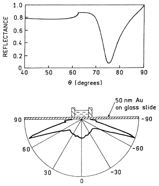
Angular dependent intensities of SPCECL (bottom). The upper panel shows the reflectivity of the gold film calculated using a gold dielectric constant of εm = −10.5 + 1.49i and the software from [23,24] and http://corninfo.chem.wisc.edu
Fig. 2.

Emission spectra of [Ru(bpy)3]2+ (top) and of SPCECL in acetonitrile (bottom).
Examination of Scheme 2 reveals that the experimental system is symmetrical around the normal (z) axis. This suggests that the emission should radiate as a cone for all azimuthal angles around the z-axis. Since the coupling angle θF is large, it is not practical to directly image this emission. We used a parabolic reflector to direct the emission towards a photographic CCD camera (Fig. 3). As expected, we observed a cone-of-emission from the plasmon-coupled emission (Fig. 3).
Fig. 3.
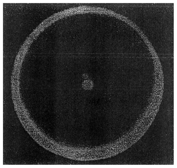
Distribution of SPCECL around the normal (z) axis.
And finally, we measured the polarization of the emission. A polarizer was positioned between the prism and the fiber optic bundle. The observation polarizer was oriented so that its electric vector was p or s-polarized (Scheme 1), which refers to in-the plane (p) or perpendicular to the plane (s) of incidence. The emission was found to be almost completely polarized in the p-direction. Since the excited states are generated chemically the emission itself cannot be polarized. Also, the polarization of the SPCE near 0.9 is larger than possible for photoluminescence from an isotropic sample. The high polarization of the emission, and its p-orientation, proves that the observed signal is due to surface plasmons (Fig. 4).
Fig. 4.

Polarization of SPCECL measured at an observation angle of 73°.
5. Discussion
There are several properties of SPCECL which make this phenomenon useful for chemical and biological assays. First, the signal is generated near the gold film, which serves as both the source of energy and the optical element for collecting the emission. This means that only ECL generated near the film will be observed, which should reduce background. This spatially localized collection of emission should be particularly useful with CL, where spontaneous reactions of the reagent or unwanted enzymatic activity can result in elevated background signals.
Another favorable property of SPCECL is that it occurs with a gold film. This is somewhat surprising because the absorption bands of gold often result in fluorescence quenching [25–28]. However, SPCE occurs over distances from the metal surface of 20–200 nm [20,21,29] which is longer than the distances for Forster resonance energy transfer quenching. The possibility of using gold as the metal is advantageous because it is chemically more stable than silver, and the surface chemistry of gold has been extensively characterized [30–32]. The use of electrodes as the energy source for emission can be readily adopted to high throughput array assays now being developed for genomics, proteomics, and drug discovery, to name a few. And finally, electroluminescence is known for organic fluorophores and semi-conductor nanopartices, expanding the usefulness of surface plasmon-coupled emission beyond medical ECL assays.
In summary we believe the use of surface plasmon coupling to collect CL and ECL signals can be a valuable addition to a wide range of analytical procedures.
Acknowledgments
This work was supported by the National Center for Research Resources, RR-08119, and the National Institute of Biomedical Imaging and Bioengineering, EB- 00682 and EB-00981, and the National Institutes of Human Genome Research HG-02655.
References
- 1.Kricka L. In: Tietz Textbook of Clinical Chemistry. Burtis CA, Ashwood ER, editors. W.B. Saunders Co; Philadelphia: 1999. p. 205. [Google Scholar]
- 2.Zhang XR, Baeyens WRG, Garcia-Campana AM, Ouyang J. Trac-Trends Anal Chem. 1999;18:384. [Google Scholar]
- 3.Kiba N, Miwa T, Tachibana M, Tani K, Koizumi H. Anal Chem. 2002;74:1269. doi: 10.1021/ac011013d. [DOI] [PubMed] [Google Scholar]
- 4.Xu XH, Bard AJ. J A Chem Soc. 1995;117:2627. [Google Scholar]
- 5.Kanou F, Zu Y, Bard AJ. J Phys Chem B. 2001;105:201. [Google Scholar]
- 6.Liu YM, Cheng JK. J Chromatography A. 2002;959:1. doi: 10.1016/s0021-9673(02)00434-x. [DOI] [PubMed] [Google Scholar]
- 7.Cao W, Liu J, Yang X, Wang E. Electrophoresis. 2002;23:3683. doi: 10.1002/1522-2683(200211)23:21<3683::AID-ELPS3683>3.0.CO;2-F. [DOI] [PubMed] [Google Scholar]
- 8.Muegge BD, Richter MM. Anal Chem. 2002;74:547. doi: 10.1021/ac010872z. [DOI] [PubMed] [Google Scholar]
- 9.Morita H, Konishi M. Anal Chem. 2003;75:940. doi: 10.1021/ac020377i. [DOI] [PubMed] [Google Scholar]
- 10.Wilson R, Clavering C, Hutchinson A. Anal Chem. 2003;75:4244. doi: 10.1021/ac034163s. [DOI] [PubMed] [Google Scholar]
- 11.Szunertis S, Tam JM, Thouin L, Amatore C, Walt DR. Anal Chem. 2003;75:4382. doi: 10.1021/ac034370s. [DOI] [PubMed] [Google Scholar]
- 12.Lakowicz JR. Anal Biochem. 2001;298:1. doi: 10.1006/abio.2001.5377. [DOI] [PMC free article] [PubMed] [Google Scholar]
- 13.Lakowicz JR, Shen Y, D’Auria S, Malicka J, Gryczynski Z, Gryczynski I. Anal Biochem. 2002;301:261. doi: 10.1006/abio.2001.5503. [DOI] [PMC free article] [PubMed] [Google Scholar]
- 14.Lakowicz JR, Gryczynski I, Shen Y, Malicka J, Gryczynski Z. Photon Spectra. 2001:96. [Google Scholar]
- 15.Malicka J, Gryczynski I, Fang J, Lakowicz JR. Anal Biochem. 2003;317:136. doi: 10.1016/S0003-2697(03)00005-8. [DOI] [PMC free article] [PubMed] [Google Scholar]
- 16.Malicka J, Gryczynski I, Kusba J, Lakowicz JR. Biopolymers. 2003;70:595. doi: 10.1002/bip.10507. [DOI] [PMC free article] [PubMed] [Google Scholar]
- 17.Lakowicz J, Malicka J, Huang J, Gryczynski Z, Gryczynski I. Biopolymers. 2004 doi: 10.1002/bip.20098. in press. [DOI] [PMC free article] [PubMed] [Google Scholar]
- 18.Raether H. In: Physics of Thin Films. Hass G, Francombe MH, Hoffman RW, editors. Vol. 9. Academic Press; New York: 1977. p. 316. [Google Scholar]
- 19.Boardman AD. Electromagnetic Surface Modes. John Wiley & Sons; New York: 1982. p. 776. [Google Scholar]
- 20.Lakowicz JR. Anal Biochem. 2004;324:153. doi: 10.1016/j.ab.2003.09.039. [DOI] [PMC free article] [PubMed] [Google Scholar]
- 21.Gryczynski I, Malicka J, Gryczynski Z, Lakowicz JR. Anal Biochem. 2004;324:170. doi: 10.1016/j.ab.2003.09.036. [DOI] [PMC free article] [PubMed] [Google Scholar]
- 22.Miao W, Choi JP, Bard AJ. J Am Chem Soc. 2002;124:14478. doi: 10.1021/ja027532v. [DOI] [PubMed] [Google Scholar]
- 23.Brockman JM, Nelson BP, Corn RM. Annu Rev Phys Chem. 2000;51:41. doi: 10.1146/annurev.physchem.51.1.41. [DOI] [PubMed] [Google Scholar]
- 24.Nelson BP, Frutos AG, Brockman JM, Corn RM. Anal Chem. 1999;71:3928. [Google Scholar]
- 25.Du H, Disney MD, Miller BL, Krauss TD. J Am Chem Soc. 2003;125:4012. doi: 10.1021/ja0290781. [DOI] [PubMed] [Google Scholar]
- 26.Dubertret B, Calame M, Libchaber AJ. Nat Biotechnol. 2001;19:365. doi: 10.1038/86762. [DOI] [PubMed] [Google Scholar]
- 27.Dulkeith E, Morteani AC, Niedereichholz T, Klar TA, Feldmann J, Levi SA, van Veggel FCJM, Reinhoudt DN. Phys Rev Lett. 2002;89(20):203002–1. doi: 10.1103/PhysRevLett.89.203002. [DOI] [PubMed] [Google Scholar]
- 28.Liu L, Wang T, Li J, Guo ZX, Dai L, Zhang D, Zhu D. Chem Phys Letts. 2003;367:747. [Google Scholar]
- 29.Gryczynski I, Malicka J, Gryczynski Z, Lakowicz JR. J Phys Chem B. 2004 in press. [Google Scholar]
- 30.Aslan K, Pérez-Luna VH. Langmuir. 2002;18:6059. [Google Scholar]
- 31.Li Z, Jin R, Mirkin CA, Letsinger RL. Nucleic Acids Res. 2002;30(7):1562. doi: 10.1093/nar/30.7.1558. [DOI] [PMC free article] [PubMed] [Google Scholar]
- 32.Letsinger RL, Elghanian R, Viswanadham G, Mirkin CA. Bioconjugate Chem. 2000;11:289. doi: 10.1021/bc990152n. [DOI] [PubMed] [Google Scholar]