Abstract
Background
ICD implants in children and patients with congenital heart disease are complicated by body size and anatomy. A variety of creative implant techniques have been utilized empirically in these groups on an ad hoc basis.
Objective
To rationalize ICD placement in special populations, we used subject-specific, image-based finite element models (FEMs) to compare electric fields and expected defibrillation thresholds (DFTs) using standard and novel electrode configurations.
Methods
FEMs were created by segmenting normal torso CT scans of subjects aged 2, 10, and 29 years and one adult with congenital heart disease into tissue compartments, meshing and assigning tissue conductivities. The FEMs were modified by interactive placement of ICD electrode models in clinically relevant electrode configurations, and metrics of relative defibrillation safety and efficacy calculated.
Results
Predicted DFTs for standard transvenous configurations were comparable to published results. While transvenous systems generally predicted lower DFTs, a variety of extracardiac orientations were also predicted to be comparably effective in children and adults. Significant trend effects on DFTs were associated with body size and electrode length. In many situations, small alterations in electrode placement and patient anatomy resulted in significant variation of predicted DFT. We also demonstrate patient specific use of this technique for optimization of electrode placement.
Conclusions
Image-based FEMs allow predictive modeling of defibrillation scenarios, and predict large changes in DFTs with clinically relevant variations of electrode placement. Extracardiac ICDs are predicted to be effective in both children and adults. This approach may aid both ICD development and patient-specific optimization of electrode placement. Further development and validation are needed for clinical or industrial utilization.
Keywords: ICD, defibrillation, modeling, pediatric electrophysiology
Introduction
Implantable cardiac defibrillators have become standard of care for patients at risk of fatal cardiac arrhythmias, and indications for their use continue to expand.1–4 Although ICD systems are routinely implanted in adult patients using a transvenous approach, there is a growing population of pediatric and adult patients in whom transvenous ICD systems cannot or should not be implanted.5 These include patients of very small size and those with intracardiac shunts or anatomical obstruction to lead placement.6–9
In these patient populations, a variety of innovative approaches to ICD implantation have been reported, including subcutaneous, epicardial and caval electrode placements and/or abdominal can implants (Figure 1).7–12 Employing ad hoc adaptations of existing ICD components, these approaches attempt to minimize system invasiveness, incorporate patient specific options to adapt to complex anatomy, and achieve low defibrillation thresholds. Assumptions of efficacy are based on extrapolation of data from the use of subcutaneous arrays in adults, limited animal research and post-implantation assessment of defibrillation thresholds.7, 9 Although defibrillation research has elucidated predictive relationships between distribution of myocardial voltage gradient and both defibrillation efficacy and myocardial injury, no information currently exists that describes the effects of interactions among variations in body size, habitus, and novel ICD geometries on these fields.13, 14
Figure 1. A. Examples of nonstandard subcutaneous, epicardial and transvenous electrode orientations.
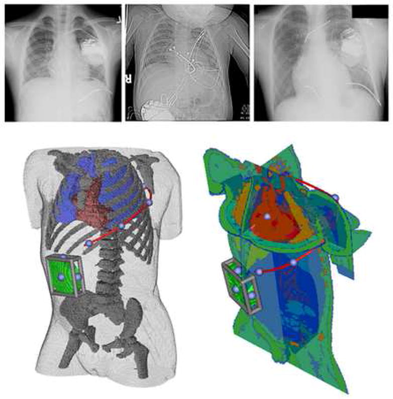
Left: Infraclavicular can with single subcutaneous electrode, Middle: Abdominal can with epicardial lead, Right: Infraclavicular can with SVC and RV transvenous electrode as well as left subcutaneous electrode. B. User interface for electrode placement. A subcutaneous electrode (red) extending left posterior with right abdominal can (green) is shown in two year old torso shown in two views used while placing electrodes in finite element model. Moveable cutting planes allow the user to examine anatomical detail during electrode placement. The blue spheres on the red electrode and bounding cage on the can indicate handles for user interaction. Electrodes can be placed with similar precision in epicardial and transvenous orientations.
Finite element modeling of defibrillation has been shown to correlate well with clinically observed defibrillation thresholds in laboriously constructed conductivity models of the adult torso.15–23 These studies have validated the use of realistic models for accurate prediction of intrathoracic electric fields, allowing estimation of the defibrillation threshold voltages, currents, and impedances that would be associated with such fields. Extension of these studies to allow modeling of different electrode orientations, within variable body sizes and habitus and under anatomically variable conditions, requires simulation systems that can facilitate rapid model creation, interactive electrode placement, and clinically relevant visualization of the results. The desire to make such tools part of the repertoire of the defibrillation research and clinical communities motivates the use of open-source tools for this purpose, so that the underlying computer code is available to the community to be improved and altered for a variety of purposes.
In this proof-of-concept study, we describe the results of subject-specific, image based finite element modeling of standard and non-standard ICD electrode placement using a novel, interactive, open-source computing environment. The driving hypothesis of this research was that alterations in electrode placement, reflecting realistic variations of surgical practice, would result in clinically significant changes in the electric fields predicted in the myocardium and thus support the goal of determining optimal electrode placements for special populations of adults and children.
Methods
Image Acquisition and Segmentation
Anatomically realistic torso models and a computer modeling environment were created in which the effect of varying ICD electrode placement on myocardial voltage gradients could be assessed as a proxy predictor of effective defibrillation. Models were constructed by segmenting 64-detector CT scans (1.25mm slices) from normal or trivially abnormal subjects obtained from a radiology trauma database with appropriate IRB approvals. Three scans were selected for this study based on 1) good tissue contrast, 2) minimal cardiac motion artifact, and 3) diversity of body size and habitus: a 12 kg female (2 yrs old), a 32 kg male (10 yrs), and a 75 kg male (29 yrs). A high-quality CT scan of a 75 kg adult female with congenital heart disease was also analyzed. Torsos were segmented into tissue compartments using the open source software package 3D Slicer (Surgical Planning Laboratory, Brigham & Women’s Hospital, Boston, http://www.slicer.org). Techniques used for segmentation included thresholding, confidence connected component analysis, and level sets. The individual segments were hierarchically combined into a single “label map” using the “unu” command line tool (TEEM, http://teem.sourceforge.net). The combined label map was then imported into SCIRun, an open-source package for scientific visualization and computation, for electrode placement and solution of the bioelectric field problem (Scientific Computing & Imaging Institute, University of Utah, Salt Lake City, http://software.sci.utah.edu/scirun.html).
Electrode Visualization and Placement
Custom modular software developed within the SCIRun package allowed the user to insert realistically shaped coil and can electrodes into images of the segmented volume with anatomical precision (Figure 1). The defibrillator can model was generated from scanned images of multiple devices by meshing the interior with tetrahedral elements. Coil electrodes were modeled by specifying the length and diameter of the contact areas separately so as to support independent variation of both parameters. The existing visualization capabilities of SCIRun were modified to support the rendering of variably-transparent, three-dimensional images of the separating surfaces between different tissue types. This interface allowed placement of coil electrodes using virtual widgets in clinically realistic positions, as judged by comparison of resulting models with AP and lateral X-rays of lead positions in exemplary patients.
Meshing and Finite Element Calculation
To complete the electrical model of the torso, we combined the label map and the user-placed electrode models into a computational mesh composed of hexahedral elements suitable for finite element modeling. Software modules were created in SCIRun to support local refinement of mesh geometry around electrodes and calculations on the resultant meshes. Elements within a 5 element thick region surrounding the electrodes were split into smaller elements to allow for a higher local mesh density.24 Using a lookup table with conductivity values, the segmented label map was transformed into a conductivity map of the torso, whose values were then projected onto the computational mesh by sampling with linear interpolation. Conductivities for the individual tissues were based on values derived from the literature as follows (all in siemens/meter): bowel gas 0.002, connective tissue 0.220, liver 0.150, kidney 0.070, skeletal muscle 0.250, fat 0.050, bone 0.006, lung 0.067, blood 0.700, myocardium 0.250.15, 17, 19, 22, 25
The resulting finite element model incorporated a set of equations similar to those used in previous defibrillation studies. In this implementation, we assumed a linear and isotropic volume conductor model, with negligible capacitance and inductance, and applied the Galerkin finite element formulation with tri-linear interpolation. Electrodes were assigned a constant potential over their surface. The mesh size and spacing was adjusted until additional refinements did not alter the results of the defibrillation threshold parameter by more than 1 percent from that obtained using a standard, dense mesh (250 × 250 × 250 elements). This resulted in a torso mesh of 1–1.5 million elements depending on the electrode configuration.
Solution Calculation, Defibrillation Metrics, and Data Analysis
After the potential distribution was solved using the finite element method, the gradients of the potential field were evaluated for the full thorax using tri-linear spatial derivatives. The critical mass hypothesis was then used to define metrics for intrapatient comparison of defibrillation “success” in different electrode configurations.15, 17, 26 Note that this approach is not intended to calculate the actual DFT which would be recorded in clinical study, but to establish a yardstick by which the intrathoracic field strength over the myocardium can be compared given differing electrode configurations. The critical mass hypothesis proposes that a defibrillation shock will be successful if it produces a threshold voltage gradient over a “large” fraction of the myocardial mass, rendering it transiently inexcitable. The criteria used in this study was a voltage gradient of 5 V/cm generated over 95% of the myocardium, values which have been accepted in the literature as a reasonable predictor of successful defibrillation.26 As the computed electrical field in our simplified model scaled linearly with the potential difference applied to the defibrillation electrodes, once the potential distribution for nominal voltages was calculated, the defibrillation voltage meeting this threshold could be simply computed.
Calculated metrics included the applied electrode voltage necessary to meet critical mass defibrillation criteria, the calculated voltage gradients and currents predicted in the myocardial elements of the model, and energy threshold (E) required for defibrillation (defibrillation threshold, DFT). The DFT in this study was calculated by the energy relation E = ½ CV2, where C is the estimated capacitance of a typical pulse generator (130 μF), and V is the electrode voltage required to meet the critical mass defibrillation criterion. We also calculated the percentage of myocardium with voltage gradient above 30V/cm at defibrillation threshold, to predict possible areas of myocardial damage.27,28 SCIRun was utilized to visualize all these parameters interactively (see Figures for examples). In addition, the percentage of myocardium above the defibrillation threshold was calculated and visualized by projecting a color scale onto the myocardial elements.
Results
Comparison to Prior Modeling and Clinically Observed Results
We carried out simulations on a reference model of a standard implant in the 75 kg adult torso, (left pectoral can to SVC and RV, transvenous orientation, shock vector AX>B). The predicted DFT in this model was 8.3J, conforming closely to both previously simulated and clinically observed results.15,17,29,30
Evaluation of Electrode Configurations
Four basic classes of electrode placement variants were simulated in each torso: can site, transvenous coils, epicardial coils and subcutaneous coils. Metrics were calculated and visualization performed for possible electrode configurations (Figure 2).
Figure 2. Example of calculation of defibrillation metrics and visualization.
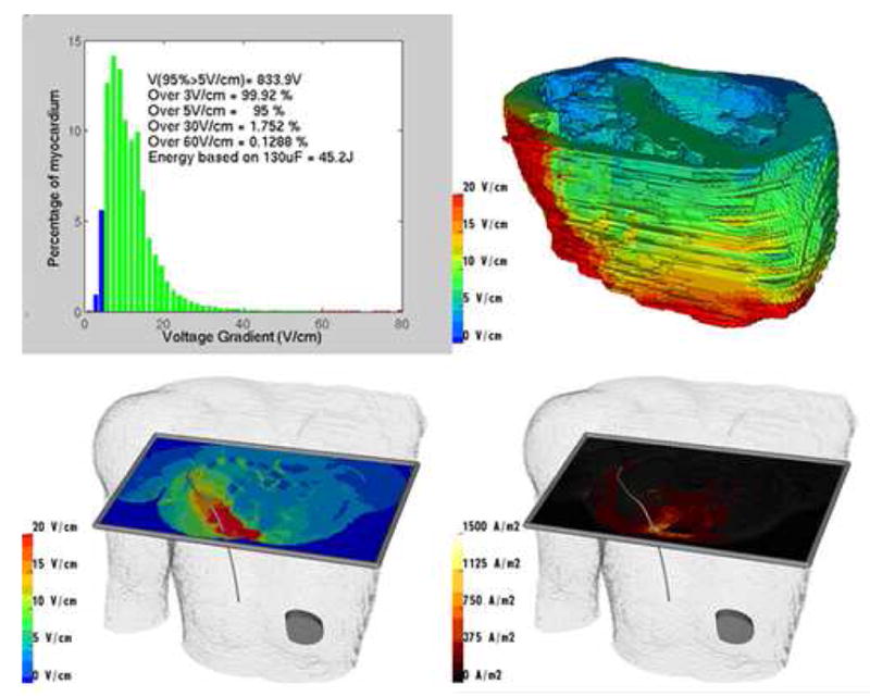
Results from exemplary model of subcutaneous right posterior electrode coil and left abdominal can in 29 year old torso. Upper left: Voltage and defibrillation metrics for myocardial elements. Upper right: Projection of voltage gradient onto portion of myocardial compartment. Lower left: Visualization of voltage gradients using interactive cutting plane. Lower right: Visualization of current density using cutting plane.
A variety of transvenous, epicardial, and subcutaneous configurations all predicted feasible defibrillation within the range of energies currently provided by ICD discharge. Transvenous orientations typically resulted in the lowest DFTs, but subcutaneous arrays and epicardial placements were also clinically feasible in all three torsos, and could be optimized by manipulation of electrode and can position. Larger body size was correlated with higher DFTs (median DFT in 10kg torso 14J [0.7 – 72J], 32kg torso 48J [4.9 – 183J], 75kg torso 85J [13 – 377J], for comparable, single can –single electrode models, p<0.0001, Kruskal-Wallis) (Figure 3).
Figure 3. Effect of varying position of 25cm subcutaneous electrode with right abdominal can.
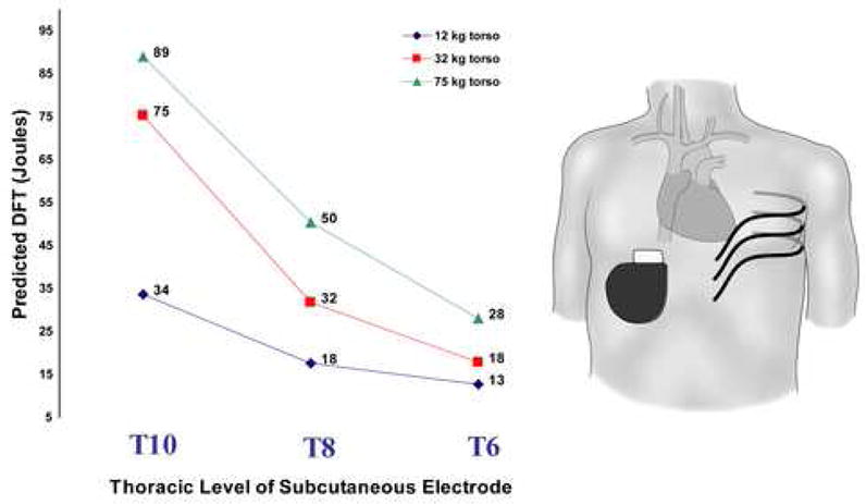
This figure also demonstrates the observed trend for increased DFT with torso size.
Can placement opposite a subcutaneous electrode resulted in lower DFTs than orientations in which the can and electrode were placed on the same side of the body (median for contralateral placement 34J [12 – 89J] vs. ipsilateral 63J [16 – 242J], p= 0.0002, Wilcoxon). The effectiveness of a can placement also depended on the relative position of the electrode and can to the heart (Figure 4 and Table 1).
Figure 4. Relation between electrode placement class and distribution of myocardial voltage gradient.
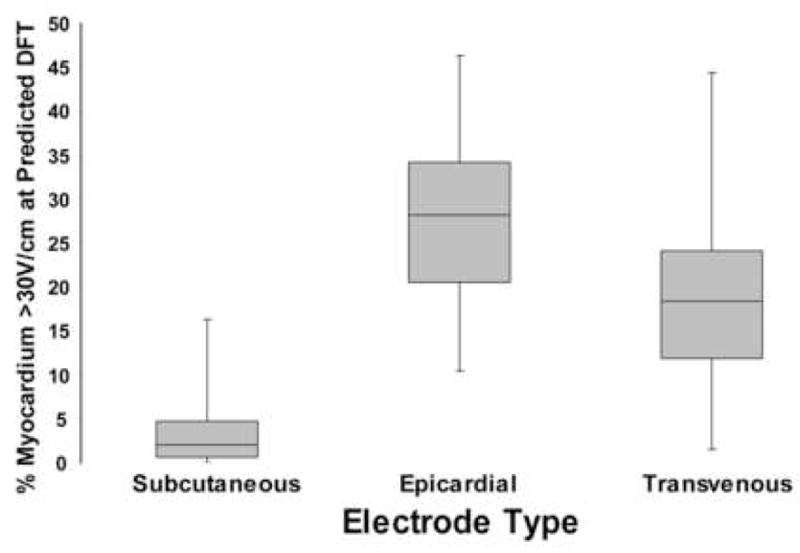
Analysis of configurations in 75 kg torso employing a single electrode coil and can shows that placement of electrodes further from heart (subcutaneous coil) results in more homogenous distribution of myocardial electrode field and smaller fraction of myocardial compartment >30V/cm when the energy applied meets criterion for defibrillation, i.e., elevation of exactly 95% of myocardial elements to a voltage gradient ≥ 5V/cm. Median, upper and lower quartiles, and range are presented.
Table 1. Effect of shock vector and can position on predicted DFTs and myocardial voltage gradients using standard, two-coil transvenous electrode.
Joules indicate predicted necessary field energy to elevate 95% of myocardial elements to a voltage gradient of 5V/cm or greater.
| Electrode configuration | Joules | % myocardium >30V/cm |
|---|---|---|
| RIC → RV + SVC | 93.2 | 18.4 |
| RIC + SVC → RV | 14.3 | 30.3 |
| RIC + RV → SVC | 22.9 | 32.2 |
| LIC → RV + SVC | 15.1 | 4.9 |
| LIC + SVC → RV *** | 8.3 | 18.3 |
| LIC + RV → SVC | 40.3 | 44.4 |
| RAC + RV → SVC | 10.8 | 19.7 |
| RAC → RV + SVC | 13.4 | 4.0 |
| RAC + SVC → RV | 11.9 | 28.6 |
| LAC + RV → SVC | 10.0 | 27.1 |
| LAC + RV → SVC | 7.5 | 14.3 |
| LAC → RV + SVC | 11.0 | 3.6 |
Can Position Key
LIC: Left infraclavicular
RIC: Right infraclavicular
LAC: Left abdominal
RAC: Right abdominal
Electrode Type Key
RV: 5cm right ventricular electrode
SVC: 8 cm superior vena cava electrode
Standard configuration
Relatively small changes in electrode position could result in significant changes in predicted DFT. Figure 3 shows the effect of a 4 rib change in placement of the 25cm subcutaneous electrode across the left chest with a right abdominal can in each torso. This change resulted in an approximately three-fold change in predicted energy needed for defibrillation, a trend observed in all three torsos.
When more than one electrode was utilized with an active can, multiple variations of the shock vector were possible. Variation of these vectors had significant effect on predicted DFTs. This is demonstrated for the standard SVC and RV electrode orientation with multiple can positions and shock vectors, shown in Table 1.
Voltage gradient distribution within the heart was highly dependent on the location and size of the electrodes. Subcutaneous electrodes tended to create a relatively homogeneous distribution of myocardial voltage gradient, while transvenous and epicardial placement resulted in a broader distribution of voltage gradient, with significant volumes of the myocardium in close proximity to the electrode exposed to voltage gradients > 30V/cm (median subcutaneous 2.1% [0 – 16.3%], median epicardial 28.2% [10.5 – 46.3%], median transvenous 18.4% [1.6 – 44.4%], p<0.0001, Kruskal-Wallis) (Figure 4). This effect was accentuated for low efficiency orientations due to the need for higher energy to meet the threshold for defibrillation.
Optimization of specific electrode configurations
Effective clinical DFTs using epicardial electrode placement have been reported9, but our model predicted relatively high DFTs for this configuration, particularly in the largest torso. Optimization of electrode/can placement was performed in this torso by changing the anatomical relations of electrodes to the heart and by varying the length of the epicardial electrode. Figure 5 demonstrates the effects of anatomical variations in electrode configuration designed to position the heart more directly in the vector created from anode to cathode, displaying a ten-fold difference in predicted DFT based on the details of electrode position.
Figure 5. Optimization of epicardial coil and can electrode placement in 75 kg torso.
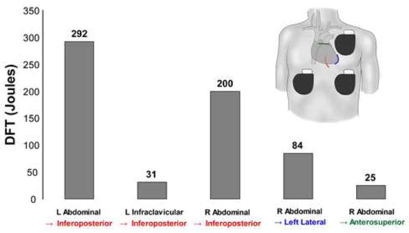
Coils are shown as colored lines overlying heart silhouette in following locations: red – inferoposterior, blue – apical, green – anterosuperior.
Examination of the voltage distributions created by epicardial electrodes revealed high local gradients around the electrode. Holding a single left epicardial electrode position constant in the adult torso with a right abdominal can, the electrode length was varied from 5 to 20 cm in length. The effect on predicted DFT and the distribution of the myocardial voltage gradient, measured as the percentage of myocardium >30V/cm, is shown in Figure 6. Increasing the length of the electrode length tended to narrow the distribution and lower the DFT, particularly with an initial increase in electrode length from 5 to 10 cm.
Figure 6.
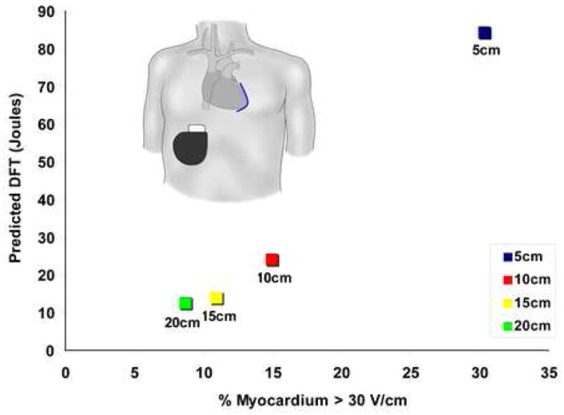
Effect of electrode length on predicted DFT and distribution of myocardial voltage gradient for left lateral epicardial electrode with right abdominal can
Therapy planning in a patient with congenital heart disease
We tested the utility of this system for the case of patient specific modeling and simulation, using an obese adult female with single ventricle physiology who underwent submammary implant of an ICD with two epicardial electrodes. After segmentation of her preoperative CT scan, electrodes and can placement were modeled to closely approximate postoperative anatomy (Figure 7). We compared simulations of various possible shock vectors with available, limited clinical implant data and found agreement between predicted and measured result trends.
Figure 7. Patient specific modeling in patient with congenital heart disease.
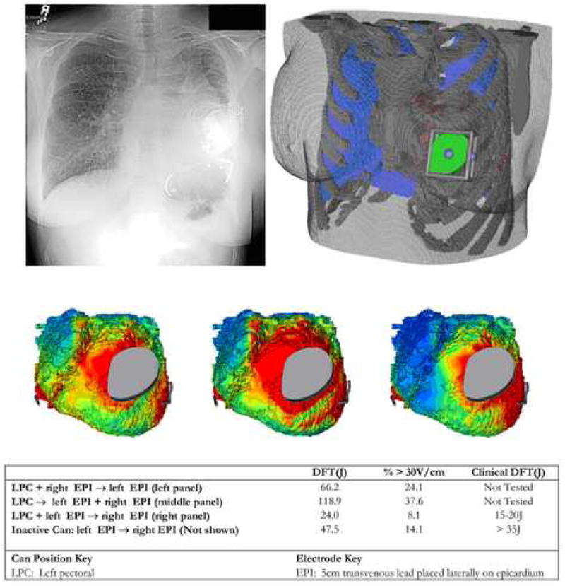
Top: Post-implantation chest X-ray and corresponding finite element model showing can and epicardial coil electrode placement. Middle: Epicardial voltage gradient distribution for three alternative shock vectors tested using model. Bottom: Predicted and observed defibrillation energies.
Discussion
Utilization of ICD therapy in pediatric and congenital heart populations has risen, as the numbers of patients who may benefit from defibrillator therapy have increased and the apparent risks of the procedure have decreased. Transvenous implantation often cannot be performed in children due to patient size, lack of vascular access and increased risk of embolic phenomena due to intracardiac shunts.5,31 Children with ICDs have high rates both of lead failure and vascular occlusion, and also have long life expectancy compared to adult patients, resulting in the anticipated need for repeated lead extraction and reimplantation with their attendant risks.1,6 There is now also growing interest in the development of extracardiac, subcutaneous ICDs for the adult population with normal cardiac anatomy, with the goal of simplifying ICD implantation, avoiding lead related complications, and/or addressing vascular access problems or other contraindications to transvenous implant. A variety of novel implantation techniques have already been explored to address problems of body size and cardiovascular anatomy.9 These attempts have been empirical, and there are little general patient-specific data available to guide optimal ICD system placements in patient populations with wide variations in body size and cardiothoracic anatomy.
In this study, we modeled a spectrum of standard and unconventional ICD electrode orientations in silico in torso models of various sizes, using an interactive electrode placement and modeling environment. The intention of this approach was not to predict defibrillation thresholds in a quantitative manner, but rather to explore trends and to provide relative comparisons of electrode performance. The principle finding of this study is that many of the surgical decisions made prior to and during ICD implant in a given patient have the potential to result in large variations of the predicted efficiency of the system. In fact, predicted DFTs generated in this initial study by modeling a range of clinically reported electrode configurations varied by as much as 10 fold in a single subject. Our results suggest that prediction of efficient defibrillation strategies using interactive, image-based models is feasible and may be used to optimize ICD electrode placement in specific patients with non-standard anatomy, to develop alternatives to standard transvenous techniques, and to test innovative ideas for the design of new devices.
As an initial benchmark, we compared results obtained in an adult torso with standard, transvenous electrode placement to previously published adult FEM models of defibrillation as well as to clinically determined values. The predicted DFT values were in close agreement with these models for standard shock vectors. Jorgensen, et al. have previously compared FEM models of defibrillation with experimental measurements in pigs, finding a correlation of 0.927 between measured and predicted thoracic and myocardial voltage, suggesting that FEM can be used to provide a good relative approximation of thoracic defibrillation fields.19 Mocanu, et al. created 7 FEM models of adult patients with prior ICD implants and compared predicted to clinically measured DFTs.22 Predicted DFTs ranged from 150 to 400 volts (approximately 4–8 joules) with four of the patients having high concordance between the predicted and clinical DFTs. Patients with poor concordance had clinical features that the investigators did not include which would be anticipated to affect either the thoracic electric field (large pleural effusions) or the response to defibrillation (infarcted myocardial tissue). Aguel and DeJongh both utilized FEM to compare transvenous electrode orientations with results closely approximating those published clinically.15,17,29,30
Although these comparisons are reassuring, neither the current nor prior models incorporate many factors (particularly myocardial) known to affect defibrillation (see below). Furthermore, the threshold predicted by the critical mass hypothesis, while supported by considerable experimental evidence, is a generalization. In this study, the myocardium is modeled using a simple monodomain approach, without anisotropy. This limits our findings to prediction of the effect of the thoracic anatomy and electrode positions on the delivery of a defibrillation field to the heart, as opposed to the response of the heart to that field. Therefore, while we do not expect this type of modeling to provide quantitatively accurate estimates of defibrillation energy, we do expect them to provide a consistent platform for comparison of relative effects of electrode position and cardiothoracic anatomy, when multiple options of electrode implantation exist. As such, they can serve as a useful tool for comparing novel electrode configurations to proven clinical standards and for evaluation of new or alternative options in a given case.
Several trends were predicted using these models. The default dual-coil implant technique employing an RV → SVC + generator shock vector generally produced the lowest defibrillation thresholds, supporting the use of this orientation when circumstances permit. Adaptation of the RV + SVC electrode with abdominal cans was also predicted to be feasible, and in some cases was slightly more efficient than the typical infraclavicular can placement. Successful defibrillation using subcutaneous electrodes also has been reported clinically, but further modeling of patients of different size, gender and habitus could provide insight into optimal electrode placement and suitable populations for this alternative implant strategy. Our results suggest that complete subcutaneous ICD systems are feasible in adults, but that the sensitivity of electrode configurations to the anatomical details of specific thorax is high and merits further exploration. Variations of the position of subcutaneous electrodes led to large changes in predicted defibrillation energy (as much as three fold with a four-rib difference in electrode placement), and lower DFTs were predicted when the subcutaneous electrode and the can were on contralateral sides of the body.
Leads close to the heart, whether transvenous or epicardial, created a resultant myocardial electric field that was less homogenous than those created by ICD electrodes remote from the heart such as the subcutaneous arrays. Such a finding necessitates that a portion of the heart to be subjected to high voltage gradients in order to raise the rest of myocardium above the voltage gradient threshold. Such gradients have been shown experimentally to have the potential to cause electroporation and potential arrythmogenesis27,28. The actual clinical morbidity associated with these effects is unknown, and perhaps represent a competing risk of certain defibrillation strategies.
Our results also predicted that defibrillation gradients may be attenuated and DFTs reduced by the use of longer electrodes in special situations, demonstrating the potential for this technique for optimization of defibrillation strategies by invention or modification of ICD generators and electrodes. For example, use of standard, 5 cm electrodes in the epicardial position was efficient in the infant torso, but resulted in impractically high DFTs as well as locally high voltage gradients using the same model in the adult torso. Extending the electrode from 5 to 10 cm resulted in the DFT being cut in half, with additional smaller gains realized by extending the electrode to 15 and 20 cm. Although 10cm coil electrodes are not currently clinically available, our results suggest that they might be useful in several clinical settings. This type of modeling allows exploration of a wide variety of system modifications prior to prototype fabrication, potentially increasing the efficiency of subsequent in vivo and clinical studies.
We thus foresee four potential uses for this modeling approach. First, using further systematic modeling studies, optimal transvenous, subcutaneous, and epicardial orientations for an average patient of a given size can be determined. This would allow clinicians to choose from a variety of known “good” configurations for the majority of patients. Second, in a smaller group of patients with normal anatomy but in whom typical orientations cannot be utilized, one could model novel electrode configurations using standard torso models of the approximate size and shape of the patient. Third, in patients in whom unique cardiothoracic anatomy dictates inventive electrode placement, dedicated imaging could be performed to create a patient specific model, as demonstrated in Figure 8. Finally, engineers tasked with the design of ICD systems could utilize this modeling environment to explore novel electrode designs and/or configurations prior to animal and human trials.
Limitations
Limitations to the FEM technique as implemented in this model are related to the various simplifications necessary to allow for effective image analysis and modeling. They include ignoring the effects of temporal (during the shock) and spatial (within organ) variability in tissue conductivity, as well as patient specific differences in the same, myocardial cellular tissue structure and fiber curvature and their effects on anisotropy of conductivity, the effect of the electrode/tissue and tissue/tissue interfaces, capacitive effects, and the effects of biphasic waveforms on membrane repolarization, all of which may affect the actual transmembrane potential induced by the potential gradient at the epicardial surface. Although results predicted by the critical mass hypothesis compare favorably to clinical observation, it is a gross model that largely ignores cellular level effects and the complexities of fibrillation wavefront behavior, and does not account for variability in susceptibility of a given patient’s myocardium. The direction of current flow between electrodes is not taken into account, nor is the interaction of the modeled field with the myocardial tissue.32
Thus the major argument against models such as this one is that they fail to completely model the phenomena of defibrillation, which at the tissue level are still not fully understood. Countering these important methodological limitations, these models are intended to explore the relative effects of variations in cardiothoracic and electrode geometries, rather than to predict DFT’s per se. Simple monodomain models such as the one presented in this study have been well-validated for that purpose, and thus we expect these models to provide a platform for reasonable comparison of the electric fields created by ICD electrodes and to be a useful tool for comparing novel configurations to proven electrode positions as well as elucidating general trends in comparison of different torso models.
It would be feasible to add to the complexity of this model by incorporating some of the more sophisticated cardiac modeling techniques pioneered by Trayanova and Efimov including bidomain models and cardiac structure.33 A bidomain model including cardiac structure could be incorporated by transferring the boundary conditions calculated from our torso model as input to a generic but more sophisticated model of cardiac excitation. However, it is unclear at this point whether addition of these features would improve the predictive utility of this model. Preliminary study of the effects of adding myocardial tissue anisotropy to models of defibrillation using the critical mass hypothesis suggests that it adds considerably to the computational complexity of the model while predicting differences in the myocardial voltage gradient field of <10%. 34, 35 Although our simpler monodomain model may not provide unbiased predictions of clinical DFTs, they may be sufficient for the purpose of optimizing electrode position, the only variable the implanting clinician can easily control.
In addition to methodological limitations, the practical implementation of our tool will benefit from further development to improve speed and ease of use. A challenge intrinsic to patient specific modeling in many fields is the implementation of accurate and rapid image segmentation with minimal need for user input. Despite improvements in image processing algorithms, model creation remains time intensive, and the goal of ongoing research is to create improved segmentation algorithms similar to those utilized in brain segmentation.36 The open-source software model used to develop these tools will allow incorporation of further contributions in these areas by academic and industrial communities.
Conclusion
We developed and used an interactive computational and visualization tool to compare relative efficiency of standard and non-standard ICD electrode placement in torso models of various sizes, demonstrating significant differences in myocardial voltage gradients associated with different strategies. In patients with contraindications to standard approaches to ICD implant, the ability to interactively assess the relative efficacy of different electrode orientations would provide insight into which orientation might be optimal in a specific patient. This image-based approach may also be of value in the design and development of novel devices and extracardiac defibrillation strategies.
Acknowledgments
This work was supported in part by NIH P41 RR12557 (Scientific Computing Institute) and NIH P41 RR13218 (Surgical Planning Laboratory). Dr. Jolley was supported by NIH T32 HL07572 and a Fast-Forward Award from the Center for Integration of Medicine & Innovative Technology (CIMIT).
Footnotes
There are no conflicts of interest to report
Publisher's Disclaimer: This is a PDF file of an unedited manuscript that has been accepted for publication. As a service to our customers we are providing this early version of the manuscript. The manuscript will undergo copyediting, typesetting, and review of the resulting proof before it is published in its final citable form. Please note that during the production process errors may be discovered which could affect the content, and all legal disclaimers that apply to the journal pertain.
References
- 1.Alexander ME, Cecchin F, Walsh EP, et al. Implications of implantable cardioverter defibrillator therapy in congenital heart disease and pediatrics. J Cardiovasc Electrophysiol. 2004;15:72–76. doi: 10.1046/j.1540-8167.2004.03388.x. [DOI] [PubMed] [Google Scholar]
- 2.Bokhari F, Newman D, Greene M, et al. Long-term comparison of the implantable cardioverter defibrillator versus amiodarone: eleven-year follow-up of a subset of patients in the Canadian Implantable Defibrillator Study (CIDS) Circulation. 2004;110:112–116. doi: 10.1161/01.CIR.0000134957.51747.6E. [DOI] [PubMed] [Google Scholar]
- 3.Buxton AE, Lee KL, Fisher JD, et al. A randomized study of the prevention of sudden death in patients with coronary artery disease. New Engl J Med. 1999;341:1882–1890. doi: 10.1056/NEJM199912163412503. [DOI] [PubMed] [Google Scholar]
- 4.Moss AJ, Hall WJ, Cannom DS, et al. Improved survival with an implanted defibrillator in patients with coronary disease at high risk for ventricular arrhythmia. New Engl J Med. 1996;335:1933–1940. doi: 10.1056/NEJM199612263352601. [DOI] [PubMed] [Google Scholar]
- 5.Kugler JD, Erickson CC. Nontransvenous implantable cardioverter defibrillator systems: not just for small pediatric patients. J Cardiovasc Electrophysiol. 2006;17:47–48. doi: 10.1111/j.1540-8167.2005.00309.x. [DOI] [PubMed] [Google Scholar]
- 6.Bar-Cohen Y, Berul CI, Alexander ME, et al. Age, size, and lead factors alone do not predict venous obstruction in children and young adults with transvenous lead systems. J Cardiovasc Electrophysiol. 2006;17:754–759. doi: 10.1111/j.1540-8167.2006.00489.x. [DOI] [PubMed] [Google Scholar]
- 7.Berul CI, Triedman JK, Forbess J, et al. Minimally invasive cardioverter defibrillator implantation for children: an animal model and pediatric case report. PACE. 2001;24:1789–1794. doi: 10.1046/j.1460-9592.2001.01789.x. [DOI] [PubMed] [Google Scholar]
- 8.Cannon BC, Friedman RA, Fenrich AL, et al. Innovative techniques for placement of implantable cardioverter-defibrillator leads in patients with limited venous access to the heart. PACE. 2006;29:181–187. doi: 10.1111/j.1540-8159.2006.00314.x. [DOI] [PubMed] [Google Scholar]
- 9.Stephenson EA, Batra AS, Knilans TK, et al. A multicenter experience with novel implantable cardioverter defibrillator configurations in the pediatric and congenital heart disease population. J Cardiovasc Electrophysiol. 2006;17:41–46. doi: 10.1111/j.1540-8167.2005.00271.x. [DOI] [PubMed] [Google Scholar]
- 10.Kriebel T, Ruschewski W, Gonzalez y Gonzalez M, et al. ICD implantation in infants and small children: the extracardiac technique. PACE. 2006;29:1319–1325. doi: 10.1111/j.1540-8159.2006.00542.x. [DOI] [PubMed] [Google Scholar]
- 11.Rashba EJ, Farasat M, Kirk MM, et al. Effect of an active abdominal pulse generator on defibrillation thresholds with a dual-coil, transvenous ICD lead system. J Cardiovasc Electrophysiol. 2006;17:617–620. doi: 10.1111/j.1540-8167.2006.00374.x. [DOI] [PubMed] [Google Scholar]
- 12.Schreiber C, Eicken A. Nonthoracotomy cardioverter defibrillator implantation in infants. Resuscitation. 2006;69(2):350. doi: 10.1016/j.resuscitation.2005.12.009. [DOI] [PubMed] [Google Scholar]
- 13.Tang AS, Wolf PD, Afework Y, et al. Three-dimensional potential gradient fields generated by intracardiac catheter and cutaneous patch electrodes. Circulation. 1992;85:1857–1864. doi: 10.1161/01.cir.85.5.1857. [DOI] [PubMed] [Google Scholar]
- 14.Zhou X, Daubert JP, Wolf PD, et al. Epicardial mapping of ventricular defibrillation with monophasic and biphasic shocks in dogs. Circ Res. 1993;72:145–160. doi: 10.1161/01.res.72.1.145. [DOI] [PubMed] [Google Scholar]
- 15.Aguel F, Eason JC, Trayanova NA, et al. Impact of transvenous lead position on active-can ICD defibrillation: a computer simulation study. PACE. 1999;22:158–164. doi: 10.1111/j.1540-8159.1999.tb00324.x. [DOI] [PubMed] [Google Scholar]
- 16.Camacho MA, Lehr JL, Eisenberg SR. A three-dimensional finite element model of human transthoracic defibrillation: paddle placement and size. IEEE Trans Biomed Engin. 1995;42:572–578. doi: 10.1109/10.387196. [DOI] [PubMed] [Google Scholar]
- 17.de Jongh AL, Entcheva EG, Replogle JA, et al. Defibrillation efficacy of different electrode placements in a human thorax model. PACE. 1999;22:152–157. doi: 10.1111/j.1540-8159.1999.tb00323.x. [DOI] [PubMed] [Google Scholar]
- 18.Jorgenson DB, Haynor DR, Bardy GH, et al. Computational studies of transthoracic and transvenous defibrillation in a detailed 3-D human thorax model. IEEE Trans Biomed Engin. 1995;42:172–184. doi: 10.1109/10.341830. [DOI] [PubMed] [Google Scholar]
- 19.Jorgenson DB, Schimpf PH, Shen I, et al. Predicting cardiothoracic voltages during high energy shocks: methodology and comparison of experimental to finite element model data. IEEE Trans Biomed Engin. 1995;42:559–571. doi: 10.1109/10.387195. [DOI] [PubMed] [Google Scholar]
- 20.Kinst TF, Sweeney MO, Lehr JL, et al. Simulated internal defibrillation in humans using an anatomically realistic three-dimensional finite element model of the thorax. J Cardiovasc Electrophysiol. 1997;8:537–547. doi: 10.1111/j.1540-8167.1997.tb00822.x. [DOI] [PubMed] [Google Scholar]
- 21.Mocanu D, Kettenbach J, Sweeney MO, et al. A comparison of biventricular and conventional transvenous defibrillation: a computational study using patient derived models. PACE. 2004;27:586–593. doi: 10.1111/j.1540-8159.2004.00491.x. [DOI] [PubMed] [Google Scholar]
- 22.Mocanu D, Kettenbach J, Sweeney MO, et al. Patient-specific computational analysis of transvenous defibrillation: a comparison to clinical metrics in humans. Ann Biomed Engin. 2004;32:775–783. doi: 10.1023/b:abme.0000030253.95538.80. [DOI] [PubMed] [Google Scholar]
- 23.Panescu D, Webster JG, Tompkins WJ, et al. Optimization of cardiac defibrillation by three-dimensional finite element modeling of the human thorax. IEEE Trans Biomed Engin. 1995;42:185–192. doi: 10.1109/10.341831. [DOI] [PubMed] [Google Scholar]
- 24.Zhang Y, Bajaj C. Adaptive and quality quadrilateral/hexahedral meshing from volumetric data. Comput Methods Appl Mech Engin. 2006;195:942–960. doi: 10.1016/j.cma.2005.02.016. [DOI] [PMC free article] [PubMed] [Google Scholar]
- 25.Geddes LA, Baker LE. The specific resistance of biological material--a compendium of data for the biomedical engineer and physiologist. Med Biol Engin. 1967;5:271–293. doi: 10.1007/BF02474537. [DOI] [PubMed] [Google Scholar]
- 26.Zipes DP, Fischer J, King RM, et al. Termination of ventricular fibrillation in dogs by depolarizing a critical amount of myocardium. Am J Cardiol. 1975;36:37–44. doi: 10.1016/0002-9149(75)90865-6. [DOI] [PubMed] [Google Scholar]
- 27.Tung L, Tovar O, Neunlist M, et al. Effects of strong electrical shock on cardiac muscle tissue. Ann N Y Acad Sci. 1994;720:160–175. doi: 10.1111/j.1749-6632.1994.tb30444.x. [DOI] [PubMed] [Google Scholar]
- 28.Alcott GP, Hunter F, Ideker RE. Principles of defibrillation: Cellular physiology to fields and waveforms. Philadelphia: Saunders; 2000. [Google Scholar]
- 29.Gold MR, Foster AH, Shorofsky SR. Lead system optimization for transvenous defibrillation. Am J Cardiol. 1997;80:1163–1167. doi: 10.1016/s0002-9149(97)00633-4. [DOI] [PubMed] [Google Scholar]
- 30.Gold MR, Olsovsky MR, DeGroot PJ, et al. Optimization of transvenous coil position for active can defibrillation thresholds. J Cardiovasc Electrophysiol. 2000;11:25–29. doi: 10.1111/j.1540-8167.2000.tb00731.x. [DOI] [PubMed] [Google Scholar]
- 31.Khairy P, Landzberg MJ, Gatzoulis MA, et al. Transvenous pacing leads and systemic thromboemboli in patients with intracardiac shunts: a multicenter study. Circulation. 2006;113:2391–2397. doi: 10.1161/CIRCULATIONAHA.106.622076. [DOI] [PubMed] [Google Scholar]
- 32.Kroll MW, Efimov IR, Tchou PJ. Present understanding of shock polarity for internal defibrillation: the obvious and non-obvious clinical implications. PACE. 2006;29:885–891. doi: 10.1111/j.1540-8159.2006.00456.x. [DOI] [PubMed] [Google Scholar]
- 33.Trayanova N. Defibrillation of the heart: insights into mechanisms from modelling studies. Experimental physiology. 2006;91:323–337. doi: 10.1113/expphysiol.2005.030973. [DOI] [PubMed] [Google Scholar]
- 34.Eason J, Schmidt J, Dabasinskas A, et al. Influence of anisotropy on local and global measures of potential gradient in computer models of defibrillation. Annals of Biomedical Engineering. 1998;26(5):840. doi: 10.1114/1.68. [DOI] [PubMed] [Google Scholar]
- 35.Wang Y, Haynor DR, Kim Y. An investigation of the importance of myocardial anisotropy in finite-element modeling of the heart: methodology and application to the estimation of defibrillation efficacy. IEEE Trans Biomed Eng. 2001;48:1377–1389. doi: 10.1109/10.966597. [DOI] [PubMed] [Google Scholar]
- 36.Pohl KM, Bouix S, Nakamura M, et al. A hierarchical algorithm for MR brain image parcellation. IEEE Trans Med Imag. 2007;26:1201–1212. doi: 10.1109/TMI.2007.901433. [DOI] [PMC free article] [PubMed] [Google Scholar]


