SUMMARY
Boundary-layer meshes are important for numerical simulations in computational fluid dynamics, including computational biofluid dynamics of air flow in lungs and blood flow in hearts. Generating boundary-layer meshes is challenging for complex biological geometries. In this paper, we propose a novel technique for generating prismatic boundary-layer meshes for such complex geometries. Our method computes a feature size of the geometry, adapts the surface mesh based on the feature size, and then generates the prismatic layers by propagating the triangulated surface using the face-offsetting method. We derive a new variational method to optimize the prismatic layers to improve the triangle shapes and edge orthogonality of the prismatic elements and also introduce simple and effective measures to guarantee the validity of the mesh. Coupled with a high-quality tetrahedral mesh generator for the interior of the domain, our method generates high-quality hybrid meshes for accurate and efficient numerical simulations. We present comparative study to demonstrate the robustness and quality of our method for complex biomedical geometries.
Keywords: mesh generation, prismatic boundary layers, local feature size, face offsetting, variational mesh optimization
1. Introduction
Computational continuum physics has become a platform for discovery in many scientific and engineering disciplines, including biomedical research. For example, the understanding of blood shear stress profiles requires numerical simulations, which can shed light on the pathophysiology of thrombus formation or rupture in cerebral aneurysms [1, 2]. Similarly, fluid and particle dynamics in the lung can shed light on airway smooth muscle spasm in asthma or abnormal clearance in cystic fibrosis [3, 4]. Many of these biomedical problems involve complex geometries, which are increasingly derived from imaging modalities such as magnetic resonance or computed tomography. While the image processing techniques have become relatively mature in recent years to extract surface geometries from medical images, these geometries are noisy and can be substantially more complex than the man-made CAD models in classical engineering problems. Therefore, significant challenges remain in the generation of computational meshes from these complex biological geometries.
For best accuracy and efficiency of numerical computations, a mesh should conform to the intrinsic properties of the geometry and the underlying physics. One notable property of many biological geometries is that they are often layered inherently. The wall of the heart, for example, is a laminated muscle consisting of three separate layers, each with a separate family of fiber and myocyte orientations. That same layering persists at the smaller scale of the heart geometry. For example, the musculature transitions into the connective tissue of the cardiac valves and at an even smaller scale where the heart muscle involutes to become a network of coronary arteries. A second and equally important property of biological geometries is that they often span multiple spatial scales, as alluded in the heart example. The lumen of a coronary artery may be several orders of magnitude smaller than the span across a ventricle, and thus there is a need to equilibrate error over a range of meaningful scales. As another example, the airways of the lung range from several centimeters to hundreds of microns.
The above properties of the geometries motivate the development of robust techniques for generating boundary-layer meshes for biomedical computations. In addition, boundary-layer meshes are desirable for viscous flows, which tend to have strong gradients at the boundary due to wall shear stress, an effect that has been shown to be extremely important in biomechanics [5, 6, 7]. An effective approach to accurately resolving viscous flows is to construct prismatic boundary layers at the wall and discretize the core of the fluid with tetrahedra. The prismatic layers have been shown to be effective in reducing errors in turbulence, particle deposition, and mass-transfer problems [8, 9, 10, 11]. Moreover, in biological fluid-structure interaction problems with a Lagrangian interface, prismatic boundary layers are also desirable near the interfaces, such as closing cardiac valves or collapsing airways during forced exhalation. In these cases, the direction of impaction is locally normal to the boundary, so it is aligned with axis of the prisms. Thus, prisms as opposed to tetrahedra will be less prone to entanglement. The height of the boundary layer is a function of the local Reynolds number, and hence to some extent is a function of a feature size of the geometry [12].
Constructing prismatic boundary layers in biological geometries presents some notable challenges. Firstly, these geometries do not have well-defined sharp features, unlike the CAD models used in classical engineering problems. Instead, they often have very large variations in curvatures. These large variations can be present as “sharp edges” or “near singularities” due to either high curvature alone or due to the combination of high curvature and coarse resolution. In addition, the challenge of constructing prismatic boundary layers compatibly across the multiple scales present in the biomedical problems, necessarily requires that some local understanding of scale be embedded in the mesh.
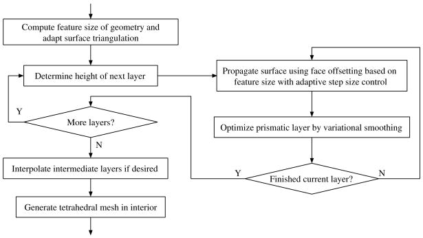
In this paper, we propose a new method for generating prismatic boundary-layer meshes that are suitable for complex biological geometries. Both image processing and isosurface extraction are important preliminaries to generating such meshes from imaging data, and both, especially the latter, have been the subject of much research (e.g. [13, 14, 15, 16, 17, 18, 19, 20, 21]). Herein, we presuppose a suitable, geometrically and topologically correct isosurface that has been appropriately manipulated to accommodate the definition of proper boundary conditions. Figure 1 shows the overall control flow of our method, given that isosurface. Like some existing methods, we generate layers with prisms near the boundary and generate tetrahedra in the interior. However, compared to existing methods, our method is novel in the following aspects: 1) We use the feature size defined in [12] to control the height of the prisms to make the resulting mesh scale invariant and prevent global self-intersections. 2) We use the face-offsetting method [22] to propagate the surface mesh to generate the prismatic layers, which provides reliable directions of vertex motions and prevents local self-intersections. 3) We develop a variational mesh optimization for prismatic layers, which improves not only the shapes of the triangles but also the orthogonality of the prisms. 4) We introduce simple and effective measures to guarantee the validity of the resulting prisms.
Figure 1.
Overall control flow of our algorithm for generation of prismatic boundary layers.
The remainder of the paper is organized as follows. Section 2 reviews some related work on generating boundary-layer meshes in three dimensions. Section 3 describes the underpinnings of our method, namely the gradient-limited feature size of a surface and the face-offsetting method for surface propagation. Section 4 introduces a novel variational method for optimizing the prismatic layers. Section 5 describes techniques for enhancing the robustness of our method and practical implementation issues. Section 6 demonstrates the results of our method on two complex biological geometries, namely a rat lung and an idealized human heart, and reports some comparisons with other alternatives. Finally, Section 7 concludes the paper with a discussion of future research directions.
2. Background and Related Work
Traditionally, mesh generation is broadly classified as structured or unstructured (see [23] for a comprehensive survey). In recent years, the generation of semi-structured boundary-layer meshes has attracted significant interest (see e.g. [24, 25, 26, 27, 28, 29, 30, 31]), as these meshes are effective for capturing large gradients and resolving viscous flows near the boundary. It is beyond the scope of this paper to give a comprehensive survey. We review some of the literature on the generation of three-dimensional boundary-layer meshes, focusing on those that have played a notable historical role or represent the current state of the art.
Most of existing methods, including those in the literature or commercial software, generate boundary layers by marching the vertices of the surface and smooth the vertex positions to improve mesh quality. For example, the advancing-layers method in [29] extrudes the surface mesh by moving its vertices nearly orthogonally to the surface to create thin layers of elements. For a triangular surface mesh, prisms are typically generated by connecting the vertices of adjacent surface layers, such as in [27, 28, 32]. The remainder of the domain away from the boundary is typically meshed with tetrahedra, using advancing front or Delaunay methods. Sometimes, the prisms are subsequently subdivided into tetrahedra for compatibility with some simulation codes [29, 30]. Some authors forego prisms altogether and simply use advancing front methods to generate anisotropic tetrahedral meshes near the boundary [25].
The key challenges in advancing-layers methods are to enforce the validity of the prismatic layers (e.g. to avoid inverted elements and self-intersections) and to obtain high quality elements in the mesh. Some earlier methods could only generate very thin layers and were not robust for complex geometries or large displacements. Garimella and Shephard [24] later proposed a generalization of the advancing-layers method to enhance robustness by adopting multiple marching directions at convex sharp edges and applying smoothing, shrinking, and pruning at concave sharp edges. The idea of multiple marching directions was later adopted by other authors [33, 26]. Athanasiadis and Deconinck [34] introduced more sophisticated methods to address these sharp features, but their method required many different types of elements (including degenerate prisms and degenerate hexahedra), which introduce additional complexities to the algorithms and may not be suitable for many simulation codes. Note that these existing techniques are mostly designed for CAD models with piecewise smooth surfaces, and they invoke special treatments at well-defined sharp features (i.e., ridges and corners). They do not address the “near singularities” caused by large curvatures or coarse resolution of the surface mesh, both of which are very common for biological geometries [35].
Most recently, Aubry and Löhner proposed a new method for the generation of viscous grids at ridges and corners [36].
A key difficulty associated with meshing concave sharp areas is the development of “swallow-tails” [37]. To avoid this problem, Sethian proposed generating meshes using a level set method, which imposes an “entropy condition” at concave regions based on the Huygens’ principle [37]. However, the level set method has completely lost the correspondence between the original and the offset surfaces, which is difficult to reconstruct, so to the author’s knowledge the method proposed in [38] was never realized in three dimensions. Recently, Wang et al. proposed generating boundary-layer meshes in three dimensions using a fast marching method with unit speed [31, 39]. However, their method does not allow for the adaptation of the marching based on the geometry or physics, and difficulties still remain in reconstructing the connectivities [39].
It is thus of great theoretical and practical interest to develop hybrid techniques that combine the efficiency and flexibility of advancing layers with the “entropy condition” of the level set methods. This combination is made possible by the face-offsetting method (FOM) for surface propagation [22], which relies on a mathematical formulation called the generalized Huygens’ principle to impose the entropy condition to explicit dynamic surfaces. However, unlike level set methods, FOM directly propagates a surface mesh, and unlike fast marching methods, FOM allows adapting the heights of the layers through a “speed function” to generate high-quality meshes and avoid self-intersections. In this paper, we apply a modification of the face-offsetting method to create hybrid meshes in challenging biomedical geometries by computing the speed function based on a feature size of the geometry, which we describe next.
3. Feature-Size Guided Face Offsetting
We first present our basic framework for the generation of prismatic boundary layers. This framework is built on top of our recent work on scale-invariant mesh generation based on a feature size function of the surface [12] and the face-offsetting method for moving interfaces [22]. We use the feature size to adapt the surface triangulation and to provide a “speed function” of face offsetting for the generation of prismatic boundary layers. This novel and natural integration will allow the generation of high-quality, adaptive boundary-layer meshes when fortified by the optimization techniques that we will introduce in later sections.
3.1. Gradient-Limited Feature Size
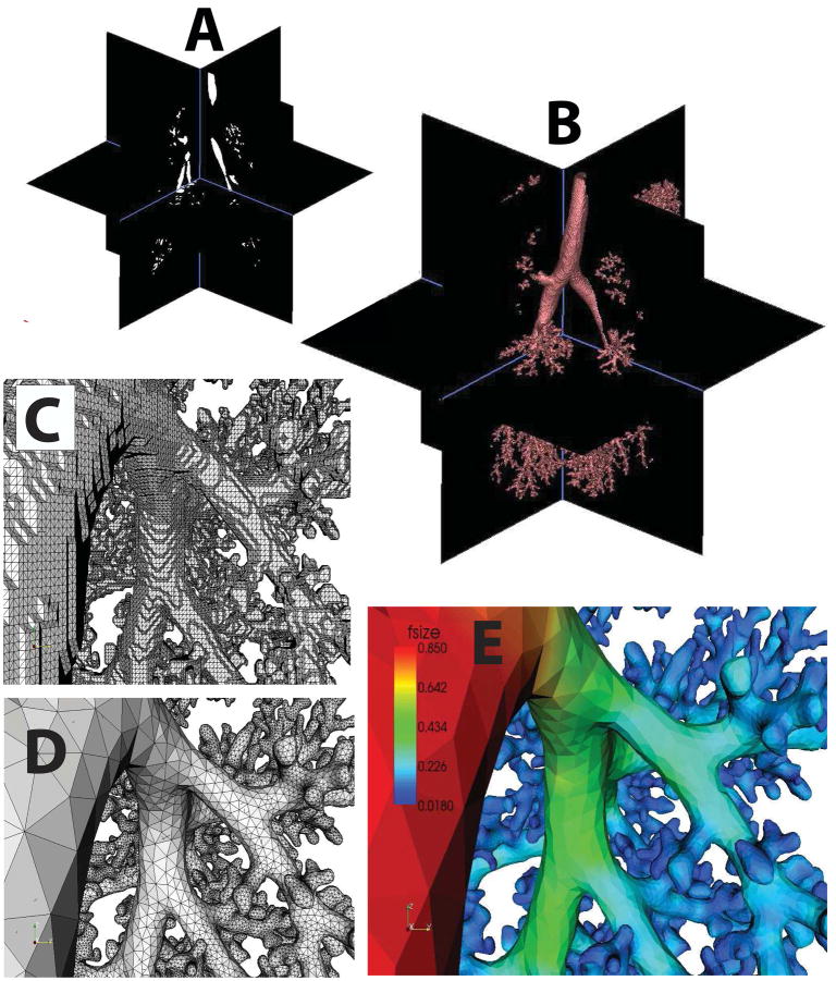
Let S be an oriented closed triangulated surface, derived from imaging data. We allow S to consist of one large enclosing closed surface S0 and possibly any number of closed surface holes S1,…Sn inside S0. Any of the surfaces S0, S1, … Sn may have handles (i.e., have nonzero genus). As illustrated in Figure 2, we modify S to produce a high-quality surface mesh S′ by performing the operations of smoothing, refinement and de-refinement while limiting perturbations to a small fraction of a voxel.
Figure 2.
Development of a scale-invariant surface mesh from MRI data: A) binary segmentation of the imaging data of a monkey lung cast; B) isosurface generation; C) detail of the isosurface; D) surface triangulation registered to the feature size; E) feature size field.
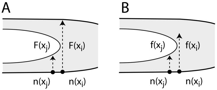
We adapt our surface mesh based on a gradient-limited feature size (or simply feature size or GLFS) defined in [12]. As we describe later, this feature size will also be used as the speed function for marching the surface layers using face offsetting. For any point x ∈ S, we define the “raw feature size” or “local diameter” F [x] as the length of the line segment formed by first shooting a ray from x in the direction of n̂in[x], the inward normal at x, and then truncating the ray at its first intersection with S (apart from point x itself; see Figure 3A). That is
Figure 3.
Without gradient limiting F[xi] can discontinuously jump with a small perturbation in the surface S due to borderline clipping of local diameter ray. With gradient limiting, this jump is generally limited to G||xi − xj||, where xj is a neighbor whose local diameter ray is robustly clipped.
| (1) |
Since S is closed, with a robust normal n̂in, the ray proceeding from x in the direction n̂in will intersect S at least once, and hence F [x] is well-defined. Similarly, we also perform an “outwards” interrogation of the geometry to compute another raw feature size field Fout[x] using n̂out = − n̂in. This outwards value is finite in some areas (e.g., at concave parts of S). Fout[x] is not used for the construction of boundary layers. However, it will be used in the adaptation of surface meshes in the next section and also in the tetrahedralization of the volume interior (or exterior) to the boundary mesh as we will discuss in Section 5.4. We note that this raw feature size is closely related to the local feature size of a surface S. The latter is defined as the minimum distance from each point on the surface to the medial axis of S (see e.g. [42]). In general, the raw feature size is at least twice as large as the surface’s local feature size.
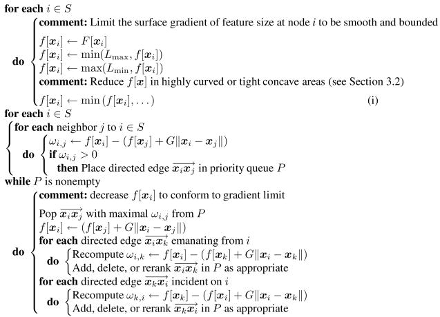
The raw feature size computed by ray tracing is bounded (Fout may be unbounded), but it is sensitive to abrupt changes in the geometry (see Figure 3). To address this, we first impose user-specified lower and upper bound to the feature size, denoted by Lmin and Lmax respectively. Thereafter, we compute a new feature size f[x] by modifying F [x], so that the spatial gradient is relatively insensitive to these changes in S. We accomplish this by performing a gradient-limiting procedure [12]. First, we initialize f[x] to F[x]. Given a bound G on the surface gradient of f[x], the algorithm places the direct edges that violate the gradient limit into a max-priority queue [43], ranked by the key
| (2) |
which measures how much the gradient violates the gradient limit for a direct edge
on S. Let
be the directed edge with the largest measure in the queue. We relax f[xi] to satisfy the gradient limit, recompute the measures for the incident edges of xi, and update the priority queue accordingly. The process continues until the queue is empty. Algorithm 3.1 summarizes the complete procedure, where the statement (i) will be explained in the next subsection. As noted in [12], 2.0 is a natural upper bound on G for the feature size to be Lipschitz continuous. In practice, we have found that G = 0.85 produces prismatic layers that are fairly parallel to the input surface mesh. For computational efficiency, ray-triangle intersections are queried within an axis-aligned bounding box (AABB) tree [44, 45] that contains at its leaf nodes the bounding box for each triangle. This algorithms has a complexity of  (n log n), where n is the number of triangles in S.
Algorithm 3.1.
Processing of Raw Feature Size(F[x], Lmax, Lmin, G,…)
3.2. Adaptation of Surface Mesh
Imaging based isosurfaces are highly irregular, noisy, and often over-resolved in some areas while under-resolved in some others. Therefore, these meshes are inappropriate as the base for the generation of prismatic layers for numerical simulations. We refine/de-refine the mesh commensurate with the feature size. During the process, we wish to preserve both topology and geometry. Topology conservation is fairly straightforward, provided that our adaptation of the surface mesh produces minimal perturbations or “damage” with respect to the original surface. To preserve the geometry, we further modify the feature size by the principal curvature of the surface to avoid under-resolving highly curved areas. We base the modification on the magnitude of the first principal curvature κ1 (aka the maximum curvature), to assure the greatest locally isotropic adaptation where needed. By the same token, we would like to constrain the tight concave areas (i.e., the areas with small Fout) by the Fout. To integrate the local values of κ1 and Fout with f[x], we simply replace the min operation at statement (i) of Algorithm 3.1 by
| (3) |
Fout, β, γ, and κ1 then become the additional input arguments to Algorithm 3.1. A natural value for γ is 2.0, because the radius of curvature is approximately equal to half the local diameter for a convex surface. However, we leave γ as a free parameter so that we can choose to refine highly curved regions according to the demands of the physics of the application. For curvature computation, we use the algorithm proposed in [46] for accuracy and stability.
To obtain well-graded, well-shaped triangles, we perform the operations of (1) Rivara edge bisection, (2) node merging, (3) edge swaps, (4) and volume conserving smoothing that are proportional to ctf[x] for some constant ct. The algorithm has been presented in [12] but is reproduced in Appendix I with consistent notation for completeness. In the next subsection, we will produce a layered prismatic mesh also according to the feature size.
3.3. Advancing Layers by Face Offsetting
Our method advances a surface layer by solving the Lagrangian evolution equation,
| (4) |
where t denotes time, n̂ denotes unit surface normal, and f(x, t) denotes the speed function as we will explain shortly. In principle, generating a layer of prisms reduces to marching the vertices in time by discretizing (4). Our method provides two options in generating a multi-layered prismatic mesh. The first option is to generate one layer of prisms per time step by connecting the vertices before and after propagation, and generate a layered mesh by taking multiple time steps. Another option is to march the surface by the desired total height of all the layers and then interpolate the intermediate layers. We refer the two options as propagated layers and interpolated layers, respectively. Both options can generate quality, graded prismatic meshes, as we will demonstrate in later experimental studies. We will focus our discussions on the first option as it can be easily extended to support the second one.
In (4), the speed function serves two purposes: 1) it controls the density of the prisms along normal direction, and 2) it can slow down the propagation of the surface at small features to avoid collisions. We note that the gradient-limited feature size (GLFS) seems to be ideal to fulfill these purposes. First, the surface mesh is adapted commensurate with GLFS, so adapting the height of the boundary layers gives some control of the aspect ratios of the prisms. Second, GLFS is approximately twice of the surface’s local feature size, so it can control the distance of the surface to the medial axis to avoid collisions. Therefore, we choose GLFS as the speed function, and “time” is then a measure of the marched distance versus GLFS. Note that unlike surface mesh adaptation, we need not limit the speed function based on the maximum curvature, and we may use different Lmin and Lmax parameters when computing GLFS.
Given the speed function, a key question in integrating Eq. (4) is the evaluation of surface normals, which is challenging for coarse meshes of noisy surfaces. In addition, it is well known that the Lagrangian equation can encounter difficulties (such as “swallowtails” or severe lagging) at strongly concave regions and large curvatures. We address these issues using the face offsetting method in [22], which is based on a geometric construction called the generalized Huygens’ principle and numerical techniques of least-squares approximation and eigenvalue analysis.
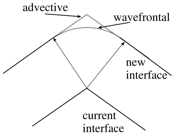
The basic idea of the face-offsetting method (FOM) is to integrate the Lagrangian evolution equation in time by advancing the faces (instead of vertices) along normal directions and then reconstructing the vertices from the displaced faces. We first advance each triangle by moving its ith vertex normal to the face for a distance proportional to the GLFS at the vertices. After displacing the faces, we reconstruct the vertices based on the generalized Huygens’ principle [22]. This principle states that every point of an interface has a field of influence (such as the trajectory of a particle in advection or a spherical neighborhood of a heat source in burning), and the new interface is the boundary of the union of the influences of all the points on the interface. This principle is more general than the classical Huygens’ principle [47] as it is applicable to both advective and wavefrontal motions, which have different behaviors at expansions as illustrated in Figure 4. If the interface remains smooth, this principle results in Eq. (4) and also the well-known level set equation [37]. Unlike those PDEs, however, this construction is well defined even at singularites.
Figure 4.
Advective vs. wavefrontal propagation at expansion.
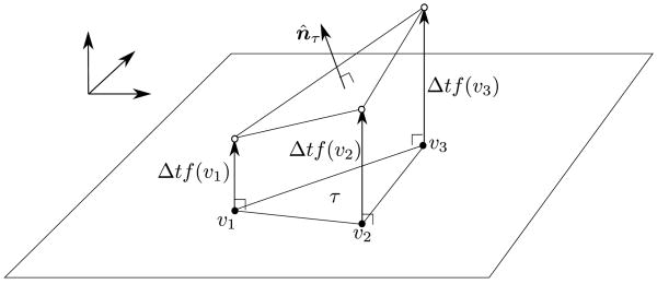
We hereafter describe the numerical solution of vertex reconstruction for advective motion. Based on the generalized Huygens’ principle, each vertex should move to the intersection of the offsets of its incident faces. In three dimensions, the intersection may be ill-defined, and we therefore formulate the intersection at each vertex as an ill-conditioned least squares approximation and solve it using an eigenvalue analysis as follows. At a vertex v, consider the computation of the displacement vector d from the vertex to its new position. Let n̂τ denote the unit normal to the offset face incident on v after displacing its vertices by Δtfv (see Figure 5), where fv denotes the GLFS at v. For each face incident on v, we obtain an equation . Suppose vertex v has m incident faces. We then obtain an m × 3 linear system
Figure 5.
Illustration of offsetting each face.
| (5) |
Let ωτ denote the area of face τ, W = diag(ω1,ωm), and . We pose (5) as a weighted least squares problem,
| (6) |
which reduces to a linear system
| (7) |
Because A is symmetric positive semi-definite, it has an eigenvalue decomposition A = VΛ Vτ, where Λ =diag(λ1, λ2, λ3) is composed of the eigenvalues of A, with λ1 ≥ λ2 ≥ λ3 ≥ 0. The ith column vectors of V, denoted by êi, is the eigenvector corresponding to λi. We refer to the space spanned by the eigenvectors corresponding to very “small” eigenvalues as the null space (or the numerical null space). For numerical stability, we filter out the components of the solution to (7) in the null space and then obtain the normal displacement for vertex v as
| (8) |
In our setting, the surface meshes are typically fairly coarse and do not have sharp features except for the boundary curves of inlet and outlet walls. Therefore, we use a simple procedure to consider an eigenvalue λi to be “small” if λi ≤ ελ1 for some ε (such as ε = 0.003 as suggested in [22]), so the summation in (8) becomes .
It is sometimes desirable to use wavefrontal motion for smoother surfaces at convex regions. We solve the wavefrontal motion using a predictor-corrector procedure: first, we “predict” a direction of motion d̂ = d/||d|| for vertex v, where d is computed using (8). Second, we “correct” the displacement along d̂ as follows. For each face σ incident on v, let sσ denote the vector from v to the centroid of the face after applying the displacements. The displacement of v within face σ is then determined based on whether the face is contracting or expanding locally at v, i.e.,
| (9) |
As in (6), let ωσ denote the area of σ. The weighted least-squares approximation of the displacement along d̂ results in a simple weighted averaging
| (10) |
We refer readers to [22] for more details. The face-offsetting method provides us an effective method to propagate the surfaces and generate prismatic mesh. However, the resulting prisms do not necessarily have good quality and may even cause inverted elements. We address these quality and robustness issues in the next two sections.
4. Variational Optimization of Prismatic Layers
For accurate and efficient numerical computations on the meshes, the prisms must have high quality. In our framework, the displacements of the vertices are decomposed into normal and tangential motions, where the tangential motion controls mesh quality. In this setting, the shapes of the triangles and the orthogonality of the side edges are particularly important. The former can affect the aspect ratios of the prisms in the boundary layers and of their adjacent tetrahedra in the interior, while the latter can affect the skewness of the prisms. Figure 6 shows some examples of poorly-shaped prisms due to poorly-shaped triangles or lack of orthogonality. We focus on these two issues in this section.
Figure 6.
Examples of poor-shaped prisms due to poor triangles with too large or too small angles (left two) and lack of orthogonality due to twisting or shifting (right two).
For flexibility, we optimize the prisms using a variational approach by minimizing a weighted sum of two potential energy functions to control triangle shapes and side-edge orthogonality, denoted by Eθ and E⊥, respectively. We compute these energies element by element and refer to the energy of each element as elemental energy. The total energy is then the sum of the elemental energies. For efficient minimization, we need to evaluate the gradient and Hessian of the energies with respect to the vertex positions of the prism. We hereafter describe the computation of the elemental energies and their derivatives and then present our overall smoothing algorithm.
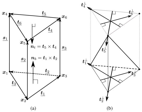
For the convenience of presentation, let us define a special naming convention of the prism and some additional notation. As shown in Figure 7(a), let the vertices of the prism be xj for j = 1,…, 6. We refer to the triangle x1x2x3 and x4x5x6 as bottom and top triangles, respectively. Let the opposite edge of xj in the top or bottom triangle be tj, and let the si = xi+3 − xi be the ith side edge for i = 1, 2, 3. In the following, i ranges between 1 and 3 and j ranges between 1 and 6, unless otherwise stated. Let us define the shorthands
Figure 7.
Naming convention of (a) vertices, edges, face normals, and (b) orthogonal directions of prism for energy computation. Underlined symbols indicate edges.
and then ti = xi− − xi+ and ti+3 = x(i−)+3 − x(i+)+3. Let nt = t5 × t4 and nb = t1 × t2, which are the inward normals to the top and bottom faces, respectively. Let ||x|| denote the 2-norm of a vector x. Let li denote ||si||, i.e. the lengths of the ith side edges. Let at = ||nt|| and ab = ||nb||, i.e., twice of the areas of the top and bottom triangles, respectively. Let , i.e., six times of the tetrahedra spanned by the bottom triangle and the side edge si, and similarly . Let denote the 90° rotation of ti in the bottom triangle pointing toward xi, and be the 90° rotation of ti+3 in the top triangle pointing toward point xi+3, as illustrated in Figure 7(b). Let ŝi = si/li, n̂t = nt/at, and n̂b = nb/ab, i.e., the unit vectors of si, nt, and nb, respectively.
4.1. Elemental Energy for Triangle Shapes
We first consider the energy for the shapes of the top and bottom triangles. Following [48], we define the energy to measure the discrepancy between the actual triangle and a reference triangle, and compute the energy in ℝ3 (instead of in ℝ2). Let Eθ,b and Eθ,t denote the energies for the bottom and top triangles, respectively, and the elemental energy of triangle distortion of a prism τ is then Eθ(τ) = Eθ,b + Eθ,t. We describe only Eθ,b, as Eθ,t can be obtained easily by symmetry.
As shown in [48], an effective energy for Eθ,b is the ratio between the sum of the squared edge lengths versus twice of the triangle area, derived from a conformal mapping between the actual triangle with a reference equilateral triangle. Its gradient and Hessian with respect to the vertex positions have simple closed forms. In particular,
| (11) |
| (12) |
| (13) |
where I is the 3 × 3 identity matrix. The residual in (13) is , which is negligible because the vertices move nearly tangentially. From (13), it can be easily shown that is symmetric positive definite as long as ab > 0.
4.2. Elemental Energy for Edge Orthogonality
We derive a new energy function for measuring the orthogonality of the side edges. Let φi be the angle between si and nb and φi+3 the angle between −si and nt, i.e.,
Assuming the prism remains valid during mesh optimization, the quality 1/cos φj is minimized if φj = 0 and approaches ∞ if φj = 90°, so 1/cos φi and 1/cos φi+3 effectively measure the deviation from orthogonality of si with respect to nb and nt. Therefore, we define the elemental orthogonality energy for a prism τ as
| (14) |
In practice, we use p = 1, as it leads to simpler formulas. Like Eθ, E⊥ is highly nonlinear. However, we can also derive closed-form formulas of the gradient and Hessian of E⊥ with respect to the vertex positions. We present the formulas here and give the derivations in Appendix II.
For convenience, let Ei = liab/Vi and Ei+3 = liat/Vi+3. First, note that
| (15) |
We obtain the following formulas for the gradients:
| (16) |
and
| (17) |
where “···” denotes the repetition of the previous row. To compute the Hessian, let us define a matrix
| (18) |
where k = 1, …, 6. We obtain the following formulas for the Hessian:
| (19) |
and
| (20) |
It is fairly easy to implement the above formulas. As for , we can omit the and terms in and .
4.3. Energy Minimization
Given the gradient and Hessian of the elemental energies, the gradient and Hessian of the total energy with respect to each vertex v is equal to the sum of those in the incident prisms of the vertex. Therefore,
| (21) |
| (22) |
where μ controls the importance of triangle shapes versus edge orthogonality. In practice, we give higher priority to orthogonality and choose μ = 0.2. After obtaining the gradient and Hessian, one could apply one step of Newton’s method to determine a displacement dv for the vertex v, i.e., by solving the equation . To preserve the height of the prisms, we constrain the vertex to move nearly tangentially within a layer. For a vertex of the current surface layer, let t̂1 and t̂2 denote two orthonormal tangent vectors at v. Let T = [t̂1 | t2]. We obtain the displacement by solving and then dv = Ty, i.e.
| (23) |
4.4. Overall Smoothing Algorithm
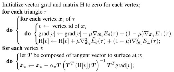
For the overall algorithm, it is most efficient and convenient to compute the gradient and Hessian of Eθ and E⊥ over all the triangles, accumulate them at each vertex, and then compute the displacements for all the vertices concurrently. This is similar to the control flow of a typical finite-element code. When applying the displacements, we determine a relaxation factor αv for each vertex and then add αvdv to the vertex, where the relaxation factor is chosen to ensure mesh validity, as we explain in Section 5.2. Algorithm 4.1 summarizes the core of this variational algorithm, which is essentially a block-diagonal solver for one step of Newton’s method. Our algorithm repeatedly invokes this procedure for a desired number of iterations or until the mesh no longer improves. This procedure is simple and efficient and delivers sufficient accuracy for optimizing prisms.
Algorithm 4.1.
One step of variational smoothing of prismatic layer(μ)
5. Robustness and Implementation Issues
The preceding sections established the theoretical foundation of our framework for generating prismatic boundary layer meshes. To obtain a robust method for practical biological computations, we must address a few additional issues, including the verification of mesh validity, adaptation of step sizes, enforcement of boundary constraints, and generation of tetrahedral mesh of the interior.
5.1. Positivity of Jacobian
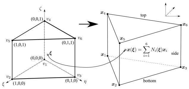
In finite element methods, the computation over a prismatic element is based on a mapping from a master element to the actual element. As illustrated in Figure 8, the mapping maps a point ξ = (ξ,η,ζ) in the master element to a point , where xi = (xi, yi, zi), and Ni is the shape function of the element associated with its ith vertex. For accuracy and stability, it is important that the Jacobian (aka the Jacobian determinant) of the mapping is positive everywhere within the element. Because the shape functions are nonlinear, it is nontrivial to verify the positivity of a prismatic element. We describe a simple and efficient technique to verify the positivity of the Jacobin for prisms in this subsection. This technique will also serve as the foundation of our method for preventing mesh folding in the next subsection.
Figure 8.
Schematic of mapping from master element to actual element for prisms.
Our technique is based on the following proposition: The Jacobian is positive everywhere within a prism if and only if it is positive along all the side edges of the prism. We outlined the proof of this proposition here, which will also motivate our definition of a quality metric for prisms in Section 6. For a prismatic element, the standard shape functions of the prism are
Using the naming conventions in Section 4, the Jacobian matrix at a point x(ξ,η,ζ) is
| (24) |
where
| (25) |
| (26) |
| (27) |
The Jacobian is then det(J). It is obvious that det(J) is quadratic, because the terms ζ2ξ and ζ2η vanish. Furthermore, det(J) is linear in ξ and η. Note that the Jacobian is nonpositive if and only if the minimum Jacobian within the prism is zero or negative. Suppose a point x0 = x(ξ0,η0,ζ0) has the minimum Jacobian. This point is contained in the triangle with vertices x(0, 0,ζ0), x(0, 1,ζ0), x(1, 0,ζ0) (which are in general not the vertices of the prism). Because the Jacobian varies linearly within the triangle, the Jacobian attains its minimum at a vertex of the triangle, which is contained in a side edge. Therefore, the minimum Jacobian is nonpositive within a prism if and only if it is nonpositive along a side edge.
Based on this observation, we can therefore check the positivity of a prism by considering only the side edges. As in Section 4, let si = xi+3 − xi for i = 1, 2, 3. Let xi,k denote xk − xi and si,k denote sk − si. Note that ξand η are constants along the ith side edge for i = 1, 2, 3. The Jacobian at the points on the edge is then a quadratic function in ζ, Ji(ζ) = aiζ2 + biζ + ci, where
| (28) |
| (29) |
| (30) |
The problem then reduces to the determination of the positivity of Ji(ζ) within the interval ζ [0, 1]. In the presence of round-off errors, the equation Ji(ζ) = 0 can be solved in a numerically stable fashion using the alternative quadratic formulas (see e.g. [49, p. 26]). Suppose Ji(0) > 0 for i = 1, 2, 3. For robustness, we consider Ji to be positive within the ith side edge only if none of its solutions is in the interval [−ε1, 1 + ε2] for some positive ε1 and ε2. In practice, we choose ε1 ≈ 10−6 to guard against round-off errors, and choose ε2 ≈ 0.05 or 0.1 so that the prism is reasonably far from degeneracy.
5.2. Adaptive Step Size Control
In our advancing layers algorithm, if the prescribed height of a layer is too large, some prisms may become folded. Such foldings can be detected by checking the Jacobian as described in the above. More importantly, we can extend the checking procedure to control the adaption of the step sizes for ensuring the validity of the mesh. At a high level, our basic idea is to verify the positivity of all the prisms, and if any prism is invalid, we then repeatedly reduce the vertex displacements and reperform the checking until all elements are valid. We apply two different variants of this procedure to normal and tangential displacements, respectively.
Let us first describe the scaling procedure for normal motions. A difficulty arises because the user seems to have lost control of the height of the prismatic layers due to the scaling of the displacements. This problem is easily overcome by employing a “subcycling” technique. In particular, within each time step we take a few substeps toward the prescribed height of the current layer while ensuring the validity of the prisms. Let xi denote the vertex coordinates of a trianglein the previous layer, di the accumulated displacements of the previous sub-steps of the current time step, and ui be the displacements of the current sub-step. We determine a scaling factor αg so that the prisms composed of vertices xi and xi + di + αgui are all positive. For simplicity, we determine αg using bisection by starting with αg = 1 and repeatedly reduce αg by half until all prisms are valid. After each sub-step, we perform a few iterations of mesh smoothing for the intermediate prismatic layer. This procedure automatically invokes more smoothing steps for more skewed meshes.
Mesh smoothing itself must also preserve the validity of the mesh. However, instead of scaling all of the vertex displacements by a global αg, we compute a different scaling factor for each vertex for more effective smoothing. In particularly, we first determine an ατ for each element τ by bisection so that the prism with vertices xi and xi + di + ατui is positive, where i = 1, 2, 3 and denotes the vertices of a triangle in the surface layer. We then set the scaling factor αv for vertex v to be the minimum of ατ among its incident triangles, i.e., αv = min{τ|v∈τ} α τ. If αv < 1 for any vertex, we scale its displacement and recompute αt and αv in its neighborhood. We repeat this process until αv ≥ 1 for all vertices, which typically terminates in very few iterations.
5.3. Enforcement of Boundary Constraints
In biomechanical simulations, it is often necessary to impose inflow/outflow conditions, such as for specifying the velocity of the blood flow at the end of a blood vessel. Boundary layers are not desired for the inflow/outflow walls, so we must extend our algorithm to accommodate these needs. For simplicity, we assume the inlet/outlet walls are flat as they are in our applications.
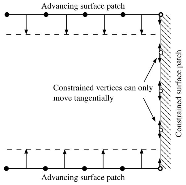
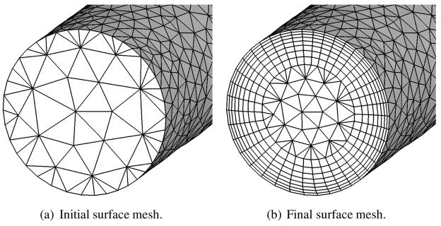
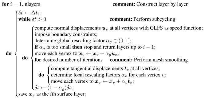
For the purpose of meshing, we consider the inlet/outlet walls as constrained patches, on which vertices can move only tangentially (i.e., only smoothing is allowed), and consider the other surface patches as advancing patches (see Figure 9). In our framework, we simply set the speed function of the constrained faces to zero when computing the vector f in (5) and then solve (7) as usual. For the vertices at the curves between the advancing and constrained patches, the displacement d from (7) would then be nearly tangential to the constrained patch and nearly orthogonal to the advancing patch, just as desired. For better accuracy, we further project d orthogonally onto the constrained surface. Figure 10 shows an example of the boundary layer mesh under boundary constraints, where the initial triangulated inlet wall in Figure 10(a) is replaced by a hybrid triangle-quadrilateral mesh in Figure 10(b). Finally, for completeness Algorithm 5.1 summarizes our overall algorithm for advancing the layers with subcycling and boundary constraints. Note that the time step Δt may differ from layer to layer to allow gradation of the mesh. Note that in the case of propagation and interpolation, we simply run the algorithm with nlayers equal to 1 and then subdivide the side edges into subintervals to obtain the intermediate layers. We have implemented our algorithm in MATLAB (more precisely, using its Embedded MATLAB subset) and compiled the code using the Real-Time Workshop.
Figure 9.
2-D illustration of constraints.
Figure 10.
Example of evolution of surface under boundary constraints.
Algorithm 5.1.
Advancing layers by face-offsetting(GLFS, nlayers, Δ ti)
5.4. Generation of Interior Tetrahedral Meshes
In general, there are two paths to follow in order to fill out the interior with tetrahedra: we can construct a tetrahedral interior and project the prisms to the original surface, or we can construct the prismatic boundary layer and fill in the tetrahedral core. The former allows more freedom in the construction and improvement of the tetrahedral core, but that freedom comes at the cost of constraints on the construction of the prismatic boundary layer. The latter path restricts the construction of the tetrahedral core in a very specific way: it must be boundary constrained. In other words, the triangulation of the interface between prismatic boundary layer and tetrahedral core must be unchanged. In this manuscript, we take the latter approach and defer the former to a future effort. Our approach to generating a boundary constrained tetrahedral core, where applicable, is due to Si [50]. We therefore outline our approach very generally and cite the excellent references that address this topic [51, 52, 53, 50]. Our approach to generating a non-boundary constrained tetrahedral mesh is presented in [12].
Given a triangulated surface mesh S from imaging data, we perform the surface operations outlined in Section 3.1 to produce S′, wherein the edge lengths are approximately to the gradient-limited feature size. Subsequently, S′is offset in the direction of the surface normals to produce,
, as outlined in section 3.3. It should be noted that
like S′ has edge lengths that are roughly proportional to the gradient-limited feature size. We construct  of
, such that the tetrahedralization of the vertices of
respects the connectivity of the triangles that comprise
. The tetrahedralization is Delaunay everywhere in
  except in the neightborhood of
. Additionally, we refine
  such that the tetrahedra are also locally proportional to the gradient-limited feature size. We do so by refining an initial tetrahedral mesh with the requirement that volumes are no greater than a fraction of a regular tetrahedron such that
| (31) |
Volume constraints on the interior tetrahedra, where f[xi] is not defined, are inherited from the surface values by a simple weighted average. Refinement proceeds by iteratively adding vertices to the interior of  , disallowing the placement of Steiner points on the boundary.
The restriction against placing additional boundary points requires that we respect a minimum sampling frequency greater than some multiple of the gradient-limited feature size in order for the topology of to be rigorously recoverable [54]. This is especially true in areas where distances between regions of the geometry can be smaller than the gradient-limited feature size. In practice it has been shown that surface point densities may be much lower than the rigorous result and still lead to successful boundary recovery [55]. To prevent connections across the boundary while disallowing the insertion of Steiner points, prior to face offsetting, S′ is also modified by Fout(x), which corresponds to an “outward” interrogation of the geometry F [x] at x using n̂out = −n̂in, as discussed in subsection 3.1.
We have found that in these kinds of regions where separate pieces of geometry lie close together, it is necessary to have the surface edge length less than 2Fout[x] in order to prevent these situations. Since we create a mesh with characteristic edge length ctf[xi], using the refinement and de-refinement operations outlined in subsection 3.2, we enforce
| (32) |
We thus reduce f[xi] where necessary so that (32) holds with equality before the final gradient-limiting operation of the feature-size field f. This can in principle lead to spots where f[xi] < Lmin, but in this case it is more important to prevent incorrect mesh topology at the expense of having some small cells.
6. Experimental Assessment and Comparisons
In this section, we assess the robustness and quality of our proposed method for generating boundary layer meshes. We report the results with two complex biological geometries: a rat lung and a human heart, and compare our method with some other alternatives. We evaluate the meshes in terms of four quality measures, which we define next.
6.1. Quality Measures for Prisms
Good quality measures are critical for assessing and comparing different methods. To the authors’ knowledge, there is no previously well-established quality measures for prisms. A measure sometimes used in the literature is the so called scaled Jacobian (see e.g., [56]). For each vertex of a prism, the scaled Jacobian at the vertex is the determinant of the matrix composed of the unit vectors of its three edges, and the measure for the prism is defined as the minimum among the values at its vertices. The scaled Jacobian was initially defined for hexahedra [57], where the three edges should ideally be mutually orthogonal. However, this measure is not ideal because a prism may be inverted even if the Jacobian (and in turn the scaled Jacobian) is positive at all the vertices, as we have shown Section 5.1. In addition, the pointwise scaled Jacobian does not attain its maximum value at the vertices of an ideal prism.
We propose a different quality measure for prisms, referred to as the scaled aspect ratio, which resolves these issues. First, we define a pointwise measure at each point within the prism as
| (33) |
where ji is given in (24). For a prism τ that has positive Jacobian everywhere, we define the scaled aspect ratio of τ, denoted by ρ(τ), to be the minimum of ρ among the six vertices; for a prism that has nonpositive Jacobian, we define ρ(τ) to be the minimum of ρ(ξ) among the points that attain the most negative value of det(J) in their corresponding containing side edges, i.e.,
| (34) |
We emphasize that our boundary-layer algorithm guarantees positive Jacobian, so ρ(τ) is simply the minimum of the scaled aspect ratio at the vertices for our method. However, positive Jacobian may not be guaranteed by some other methods, and the general definition above is necessary for our comparison purpose later.
This scaled aspect ratio has both geometric and algebraic meanings. The magnitude of the first term in (33) measures the aspect ratio of the triangle with edges j1, j2, and j1 − j2, and it resembles the inverse of the triangle-shape energy (11). The inner product in (33) resembles the inverse of the terms in the edge-orthogonality energy (14). Therefore, this quality measure in effect combines the measures of triangle shapes and edge orthogonality, which we optimize in our mesh smoothing step. Note that ρ(τ) ∈[−1, 1], ρ= 1 for ideal prisms, and ρ≤0 indicates an inverted element. Algebraically, we can rewrite (33) as
| (35) |
where J is given in (24). From (35), it is apparent that the scaled aspect ratio involves just a simple adjustment to the scaled Jacobian for prisms. We refer to our measure as scaled aspect ratio to signify its geometric meaning.
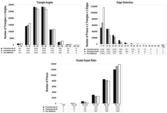
Besides scaled aspect ratio, we also consider the statistics of the angles of the triangles (60° is ideal) and the distortion of the side edges with respect to the face normals, which we refer to as triangle angles and edge distortion, respectively. We compute the latter as the angles between the side edges and the upward normals to the triangles of the prisms, so 0° is ideal. These can be considered as measures of triangle shapes and edge orthogonality, respectively. Although the scaled aspect ratio already contains information about both of these measures, these statistics are more intuitive to understand and sometimes quite revealing. For the tetrahedral interior, we report the aspect ratio χ of a tetrahedron, defined as
| (36) |
which has a maximum value of 1.0 for regular tetrahedra.
6.2. Rat Lung
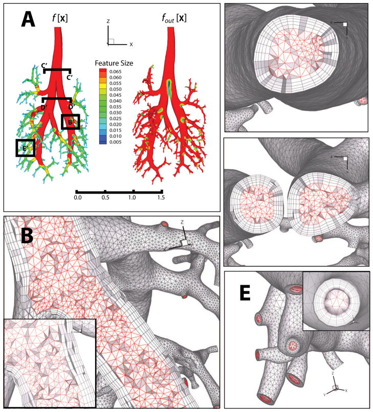
Our first example geometry, as shown in Figure 11, is a rat lung, whose surface has genus 0. Magnetic imaging data was acquired using silicone casts of pulmonary airways in a 9-wk-old, male, Sprague-Dawley rat. The imaging data were segmented and the surface was extracted with a variant of the marching cubes algorithm [20]. Panel A shows the gradient-limited feature sizes (GLFS) f[x] and fout[x]. Meshing parameters for surface mesh adaptation were set to ct = 0.6 and γ= 2.0, and the adapted surface mesh contained 162,923 vertices and 325,842 triangles.
Figure 11.
Boundary layer mesh of a rat lung. Panel A shows the feature size fields on the lung surface, as well as the locations of the cutaway sections in panels B–E. Panel B shows the boundary prism and interior tetrahedra at a region where a large airway transitioning to a smaller airway. Panels C and D show the sections through the trachea and through a pair of airways downstream of the bifurcation, respectively. Panel E shows the resulting surface mesh in the neighborhood of several outlets, where the faces are constrained (see subsection 5.3)
6.2.1. Assessment of Quality
Our algorithm generated five layers of prisms for a total height of about 26.5% of the GLFS f[x]. The layers were graded with an exponent of 1.2, so the height of first layer was about 3.56% and that of the last layer is about 7.38% of f[x]. We used face-offsetting with both shape and orthogonality optimization and with interpolated layers. Offsetting and construction of the prismatic layers took about 36 minutes on a PC with a 3GHz Intel Core 2 Duo CPU. The generation of the tetrahedral mesh took about 2 minutes. The resulting hybrid mesh is shown in Figure 11. Panel B shows the prismatic boundary layer and interior tetrahedra in a large airway where f[x] Lmax, transitioning to a smaller airway where Lmin < f[x] ≤ Lmax. Comparing Panels C and E, it is clear that the ceiling (Lmax) on the feature size results in a tighter layering in regions where f[x] Lmax. Panels C and D show sections through the trachea and a pair of airways downstream of the bifurcation, respectively. Panel E shows both the external boundary and the prismatic layer in the neighborhood of several outlets that are roughly 1/30 of the diameter of the trachea. The outlet surfaces in panel E illustrate the enforcement of the boundary constraints of the prismatic boundary layers described in subsection 5.3.
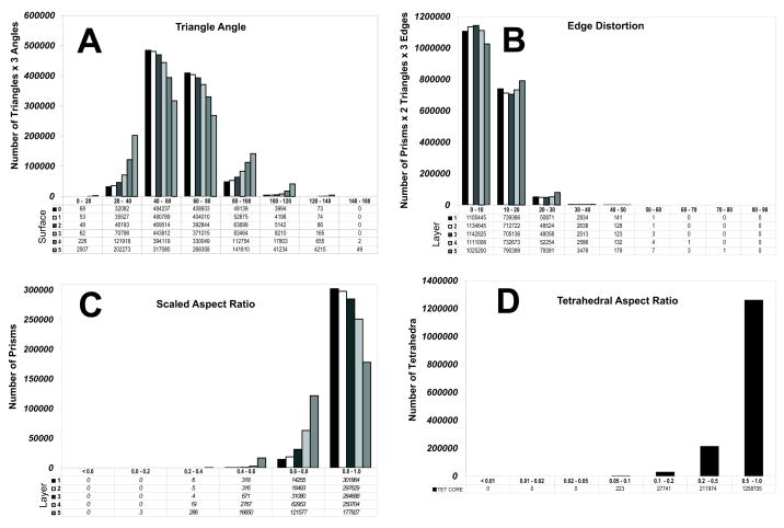
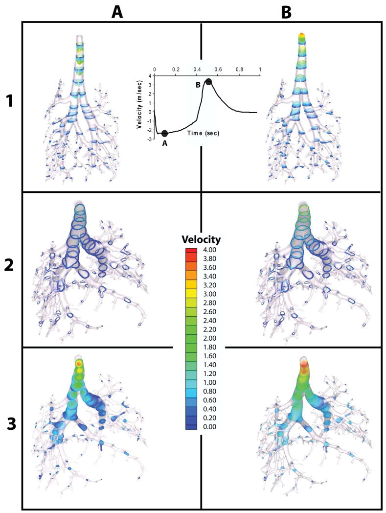
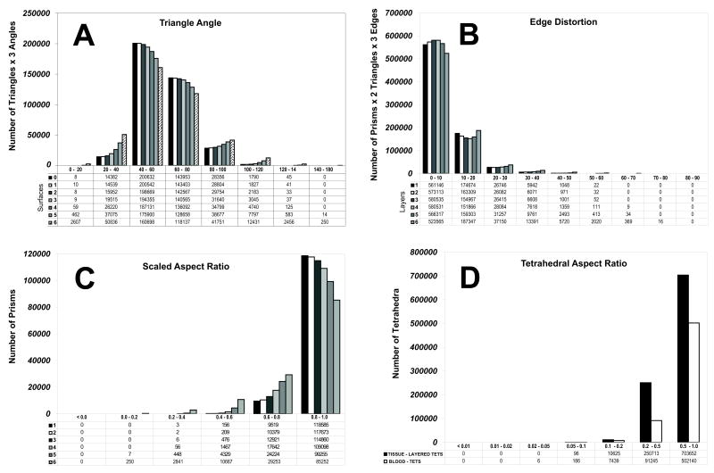
Figure 12 shows three prism statistics: triangle angles, edge distortions and scaled aspect ratios for the five layers generated, along with the conventional aspect ratio for tetrahedra. Note that the vertical axes for both aspect ratios are the numbers of their corresponding elements. However, for the triangle angles, the vertical axis is equal to the number of triangles times three, and for edge distortion it is equal to the number of prisms times six (since there are two triangles and three side edges per prism). Overall, mesh quality statistics were excellent for both prismatic layers as well as for the tetrahedral interior. As can be readily seen, the peak angle from the original surface mesh to the final offset surface degrades from 60° to about 50°. However, even at nearly 27% propagation the distribution remains excellent. The same trend can be seen in the edge distortion statistics, where peak distortion remains in the 0° – 10° range, and in the scaled aspect ratios, where the peak is in the 0.8 to 1.0 range. Only 3 prisms were in the 0.0–0.2 range in the final layer, with a minimum of 0.055. The quality of this mesh is well suited for computational fluid dynamics. In fact, we have employed the mesh in a transient CFD simulation. It is beyond the scope of this paper to report detailed simulation results using boundary-layer meshes, which we will report elsewhere. Nevertheless, Figure 13 shows the result from a transient CFD simulation using our meshes, demonstrating the usability of our method for biomedical computing.
Figure 12.
Mesh-quality statistics for the prismatic layers and interior tetrahedra of the rat lung mesh generated using our proposed method. Panel A shows the angles for each surface layer, starting with the original surface mesh (60° is ideal). Panel B shows the edge distortion of each prismatic layers (0° is ideal). Panel C shows the scaled aspect ratio of prisms for each prismatic layers (1.0 is ideal, and a negative value would indicate an inverted prism). Finally, panel D shows the aspect ratios for tetrahedral elements (1 is ideal)
Figure 13.
Transient CFD results for the pulmonary airways of 9-wk-old, male, Sprague-Dawley rat. Flow data (inset) were experimentally determined from a mechanical ventilator and prescribed to the trachea. Downstream outlets were uniformly prescribed zero pressure boundary conditions. Columns A&B correspond to time points A&B on the inset velocity curve, roughly corresponding in turn to peak inhalation and peak exhalation. Velocity vectors and velocity contours through each domain (prismatic or tetrahedral) are shown in respectively in rows 1–3. Note the strong gradient in the prismatic layer of the trachea, where Reynolds numbers reach ~ 3000
6.2.2. Comparison of Different Alternatives
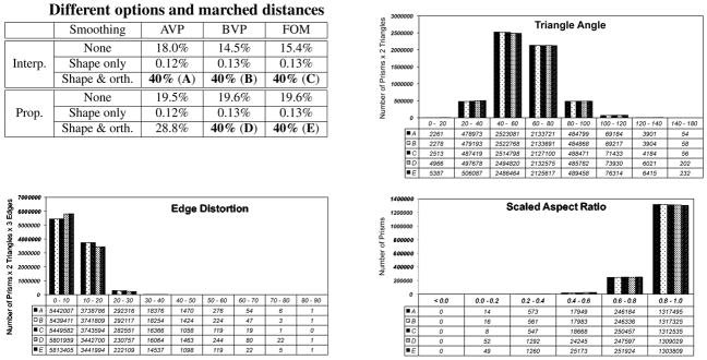
To get an indirect comparison with other methods, we note that most competing algorithms are based on the idea of vertex propagation rather than face offsetting. To our knowledge, few (if any) of the existing methods optimize the orthogonality of prisms. We therefore compared our method against vertex propagation (VPM) using area-weighted vertex normals, which were chosen for its better resistance to noise for poor shaped meshes. We compare VPM versus face offsetting (FOM) and evaluate the relative importance of the optimization of triangle shapes and edge orthogonality and of interpolated versus propagated layers. We ran twelve different cases, as indicated in the first panel in Figure 14, where “interp.” indicates the propagation by a single big layer followed by interpolating the intermediate layers, and “prop.” indicates the propagating one layer per step. For each case, we set the target of propagation to 27% of the GLFS. Subcycling was performed whenever necessary, and the propagation was stopped if the subcyling time step became too small (≤10−5). For the layer-by-layer construction, the layers are also graded with an exponent of 1.2, so the height of first layer is about 3.63% and that of the last layer is about 7.52% of GLFS. As shown in the first panel in Figure 14, only the methods with the full variational optimization marched or nearly marched the desired distance, while all the others failed before reaching 10% or even 1% of the GLFS. Note that for layer-by-layer propagation, the algorithm cannot produce the full five layers unless it successfully finishes the complete distance specified by the user. On the contrary, the interpolation schemes can produce a layered mesh even if the propagation fails prematurely.
Figure 14.
Comparative statistics for prismatic layers generated using alternative options. We compare vertex propagation (VPM) versus face offsetting (FOM) and evaluate the relative importance of smoothing and of interpolated versus propagated layers. First panel shows the options used for each series and also their corresponding marched distance as percentage of GLFS. Remaining panels show the quality metrics for methods that generated the desired number of layers.
The last three panels in Figure 14 shows the statistics of the prismatic layers for the cases that generated five layers. It is worth noting that when optimizing only triangle angles (series E and F), both FOM and VPM produced good surface meshes but highly distorted side edges, so the quality of the prisms deteriorated quickly and resulted in failures at a very early stage. However, with the optimization of both triangle angles and orthogonality, both FOM and VPM produced quality meshes for this geometry. We note that VPM was about 20% slower than FOM because VPM required far smaller time steps than FOM to avoid the formation of negative prisms.
6.3. Human Heart
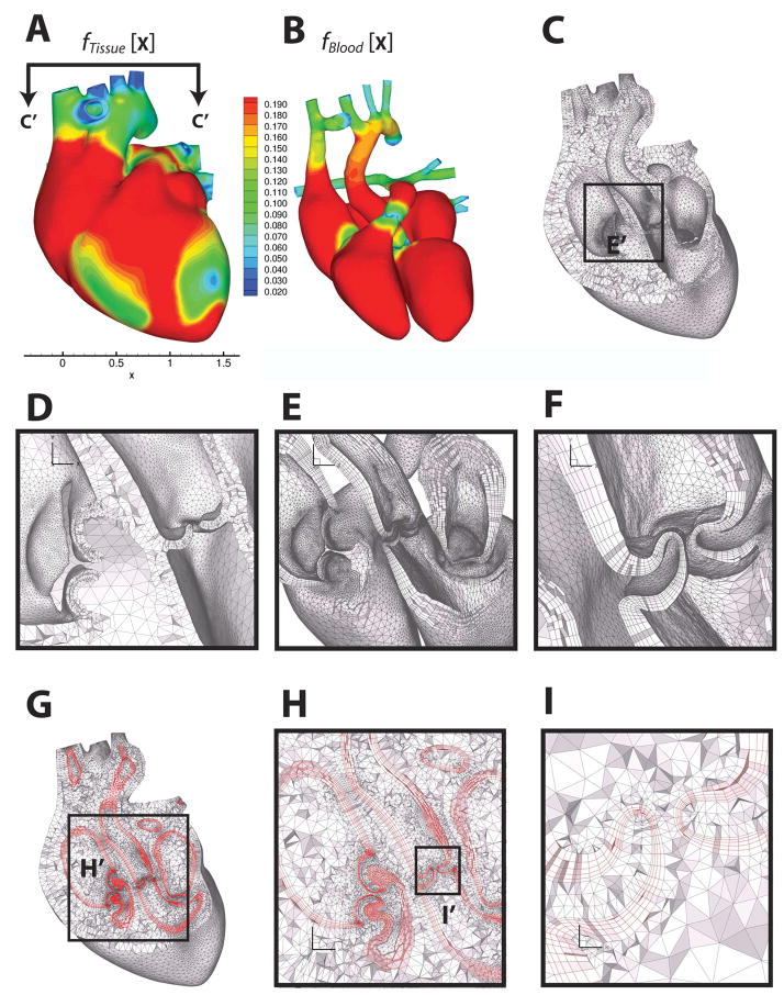
Our second example, as shown in Figure 15, is an idealized human heart model. This model was originally due to the NYU Medical Center. It is relatively realistic and highly complex topologically, with a genus 12. We started with a triangulation of the model in [58, 59], which we enhanced to make it multi-material and then adapted to commensurate with the gradient-limited feature size. The heart mesh is composed of two distinct material regions: the heart musculature and the enclosed blood. The blood region in turn consists of two disconnected components, the left and right ventricular and atrial cavities. Panels A and B of Figure 15 show the GLFS of the tissue fTissue[x] and blood fBlood[x], respectively, which were constructed with the same parameters (Lmin, Lmax, ct = cn = 0.6). For the heart, we constructed three, instead of two mesh domains. The tissue of the heart muscle was tessellated by a layered tetrahedral meshing algorithm described in [12]. The interior surface of this layered tetrahedral region was the boundary of the blood region that was to be offset. Within the offset boundary, we produced a boundary-constrained tetrahedral core. Meshing parameters for modification of S′ ← S were set to ct = 0.6 and γ = 1.5, resulting a surface mesh with 64,865 vertices and 129,722 triangles. The reduction of γ from 2.0 to 1.5 allows better capturing the highly curved free-edges of the cardiac valve leaflets.
Figure 15.
Multi-material boundary layer mesh of a human heart, consisting of heart tissue, blood boundary layer and blood domains. Panels A and B show the feature size field on the outer surface of the heart tissue domain and the blood domain, respectively. Panel B shows the feature size field on the outer surface of the blood domain. Panel C shows a cut through the heart muscle tessellated with layered tetrahedra [12], where the orientation of the cut plane is indicated in Panel A. Panel D shows the detail of the layered tetrahedral mesh of the heart tissue. Panels E and F are zoomed-in views on the regions of the cardiac valves, showing the prismatic boundary layer alone. Panels G, H and I show the prismatic boundary layer at about 25% of GLFS of the blood domain, sandwiched between the layered tetrahedra of the tissue and the Delaunay tetrahedra of the blood. Heart model and surface mesh are courtesy of the NYU Medical Center and Zhang et al. [58, 59].
6.3.1. Assessment of Quality
We first generated a six-layer prismatic mesh with our method by marching for about 24% of the GLFS of the blood domain, again using the default mode of our proposed method, namely face offsetting with both shape and orthogonality optimization and with interpolated layers. The propagation and construction of the prismatic layers took about 20 minutes on a PC in the same setting as for the lung mesh. The generation of the tetrahedral mesh for the heart tissues took 30 minutes, and that for the blood region took 5 minutes. The resulting hybrid, multi-material mesh is shown in Panels C–I of Figure 15. Panels C and D show the layered tetrahedral tissue mesh in isolation. In this case, we chose to generate three layers of tetrahedra, corresponding to the histologically distinct myocardial, valvular and arteriovenous layers. The prismatic boundary layer is shown in Panels E and F. Note the ordered layers of prisms transitioning from the larger myocardial scale to the lower valvular scale. Panels G, H and I show the three regions integrated at various levels of scale.
Figure 16 shows the three prism statistics: triangle angle, edge distortion and scaled aspect ratio for the six layers generated, as well as the conventional aspect ratio for tetrahedra. Again, mesh quality statistics were excellent for both prismatic layers as well as for the tetrahedral tissue and blood layers. The distribution of triangle angles was excellent and did not significantly degrade in the final offset surface. The same trend can be seen in the edge distortion statistics, where peak distortion remained in the 0°–10° range. Only a few prisms had a distortion greater than 70°, with a maximum of 77°. In terms of the scaled aspect ratio, the majority of the prisms are close the 1.0, the ideal value. Only a handful were in the 0.0–0.2 range, with a minimum of 0.085.
Figure 16.
Mesh quality statistics for the prismatic layers and interior tetrahedra of the human heart mesh generated using our proposed method. Panel A shows the angles for each surface layer (60° is ideal). Panel B shows the edge distortion of each prismatic layer (0° is ideal). Panel C shows the the scaled aspect ratio for prisms of each prismatic layer (1 is ideal, and a negative value would indicate an inverted prism). Finally, panel D shows the aspect ratio for tetrahedral elements (1 is ideal)
6.3.2. Comparison of Different Alternatives
As for the lung mesh, we compared a number of methods for generating prismatic boundary layers, including face offsetting as well as vertex propagation using normals computed by area weighted averaging (which we refer to as AVP) or by the method proposed by Kallinderis and Ward in [27] (which we refer to as AVP). For each method, we ran both propagated layers and interpolated layers and used three mesh optimization options as for the lung mesh. These amount to 18 different variations. For each varient, we march the surface as far as possible, and recorded the marched percentages of GLFS in Table I. Most methods marched less than 10% of the GLFS. The clear winner was the default mode of our proposed method, namely face offsetting with shape and orthogonality optimization and with interpolated layers, which reached 27%. The second place is vertex propagation using the normal computation of Kallinderis and Ward, augmented wtth our shape and orthogonality optimization and intermediate layer interpolation, which marched 17.1%. The third place is vertex propagation using average vertex normal, also augmented wtth our optimization and interpolation techniques. These results again show confirm that our optimization and interpolation techniques are effective in enhancing the robustness of the generation of prismatic boundary layers. In addition, this example also demonstrates that FOM can be significantly more robust than vertex propagation for complex geometries.
Table I.
Marched percentage of the GLFS for heart geometry using different methods. “Prop.” and “interp.” refer to propagated and interpolated layers, respectively.
| AVP | BVP | Face offseting | ||||
|---|---|---|---|---|---|---|
| Prop. | Interp. | Prop. | Interp. | Prop. | Interp. | |
| No mesh optimization | 3.8% | 2.7% | 3.5% | 5.8% | 3.6% | 8.0% |
| Optimize shape only | 6.0% | 5.9% | 6.1% | 6.1% | 10.0% | 9.1% |
| Optimize shape & orth. | 8.0% | 12.5% | 9.5% | 17.1% | 9.9% | 27% |
There appear to be two main reasons for VPM to be less robust than FOM. First, the heart mesh contained some convex areas with large curvatures, which quickly evolve into sharp edges after a moderate amount of propagation due to the coarse mesh resolution. These sharp edges cause difficulties for normal computations, even for the normal computation in [27], causing some vertex normals to point opposite to some face normals and in turn negative Jacobian. FOM overcomes the problem using an eigenvalue analysis to deliver more reliable directions for the propagation. The second reason is that unlike FOM or the level set methods, VPM is not based on the Huygens’ principle (or its generalization) and can lead to severe lagging at sharp convex regions. This deficiency of VPM tends to accelerate the formation of sharp edges and cause early termination of the propagation. Note that these difficulties with convex sharp edges are the main motivations for the use of multiple normal directions in previous methods [24, 33, 26], which are unfortunately difficult to apply for complex biological geometries, because the sharp edges do not correspond to well-defined sharp features in the surface, and they emerge dynamically during the propagation of the surface.
6.4. Comparison with Commercial Software
Our comparisons with other methods for the lung and heart meshes were based on our own implementations of different alternatives, so they only serve as indirect comparisons with other methods. Due to the lack of standard benchmarks, it is admittedly difficult to compare against other software implementation. For completeness, we nevertheless report a comparison against a leading commercial software. Like a few others, this software can import a surface mesh to reconstruct the geometry (a discrete CAD model) and then generate a boundary-layer mesh using different algorithms. The algorithms supported by this software include one that produces uniform heights of the prisms, one that adapts the heights of the prisms based on the edge lengths of the initial input surface, and one that adapts the heights of the prisms based on the edge lengths of the propagated surface. None of these options allows the adaptation of the boundary layer based on a user-specified field, such as the GLFS. However, since our surface meshes are adapted based on the GLFS, the latter two options can indirectly adapt the heights of the prisms based on GLFS. Therefore, we therefore compare our method against the latter two algorithms and refer to them as Commercial A and Commercial B, respectively.
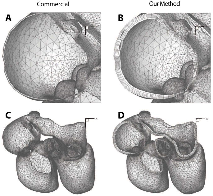
We first attempted to generate prismatic boundary layers from the lung and the heart surface meshes. Even after our best effort (including consultation with the principal developer of this capability in the commercial software), for the lung mesh the commercial software failed to properly reconstruct the surface patches, which is a pre-requisite for the software to generate boundary-layer meshes. For the heart mesh, the software successfully reconstructed the surface patches, but it repeatedly generated prismatic meshes that had self intersections or that were too skewed for that software itself to produce a valid tetrahedral mesh. With our best possible effort, we were able to generate only a very thin layer of prisms to cover approximately 3% of the domain using Algorithm B of the software. Figure 17
Figure 17.
Comparison of prismatic boundary layer generated using a leading commercial CFD mesh generator and our method.
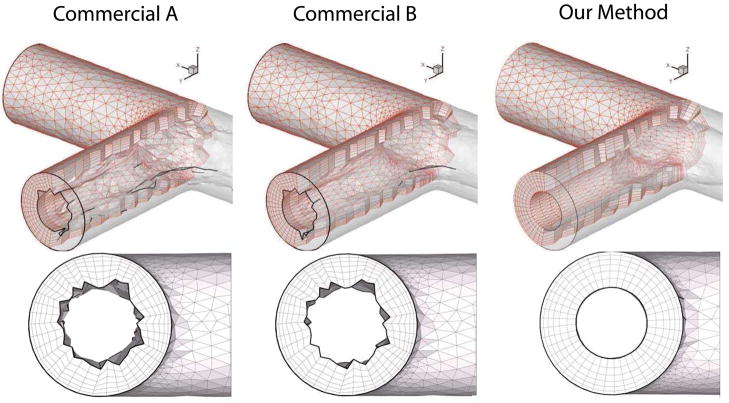
The above tests demonstrated the tremendous difficulties in generating prismatic boundary-layer meshes for complex geometries even for the state-of-the-art commercial software. This is not surprising, because as we noted earlier, most existing methods and software for boundary layers are designed for CAD models, so they are not well suited for complex geometries from medical imaging. The commercial software with which we compared was no exception. In order to compare the quality of the meshes generated by our method against commercial software, we resorted to a simpler geometry. We chose a simple T shaped intersection of tubes. After many unsuccessful trials, the commercial tool reported successful generation of prismatic elements using either of the two algorithms, which apparently marched about 35 to 45% of the GLFS. The left two panels in Figures 18 show the resulting meshes, which were visibly jagged and skewed. Such jagged boundary-layer meshes appear to be common for some other software as well. In this comparison, we set our method to march 50% of the GLFS for this geometry, and the last panel in Figures 18 shows the resulting mesh using our method. In contrast, the mesh from our method was visibly far smoother because of its variational nature.
Figure 18.
Comparison of mesh quality of prismatic boundary layer generated using commercial software and our method. Solid curves indicate ridge curves in the surface mesh with dihedral angles close to 90°.
Figure 19 shows the statistics of the prismatic layers using the commercial software as well as our method in terms of the triangle angles, edge distortion, and scaled aspect ratios. It is worth noting that the commercial software appears to deliver better triangle angles than ours. However, because that software does not optimize the orthogonality of the prisms, it caused severe edge distortion and even inverted elements. Overall, the mesh from our method is superior in terms of the scaled aspect ratio. This result is consistent with our observations in Figure 14 for the lung mesh, where both VPM and FOM with only triangle-shape optimization delivered excellent triangles but highly distorted side edges, and in turn poor robustness and mesh quality. These results demonstrate that our method is more robust and can produce higher quality meshes than this (and likely some other) state-of-the-art, commercial software.
Figure 19.
Comparison of mesh quality statistics of prismatic boundary layer generated using commercial software and our method.
7. Conclusions and Discussions
In this paper, we introduced a new method for generating prismatic boundary-layer meshes for complex biological geometries. Our method uses a gradient-limited feature size (GLFS) to guide the generation of the prismatic mesh at the boundary layers and the tetrahedral mesh in the interior. Unlike previous approaches, which propagate vertices along some vertex normals, our algorithm uses the face-offsetting method (FOM) to advance the surfaces. In addition, we introduced a novel prismatic variational smoothing procedure to improve bases triangle shapes and edge orthogonality. Our experimental study showed that the face-offsetting method is more robust than traditional methods based on vertex propagation, and our variational smoothing further enhances the robustness substantially and enables high-quality prismatic meshes. In addition, our experimentations also demonstrated that it is in general more robust to propagate the surface and then interpolate the intermediate layers than propagating the surface layer by layer. Combined with a robust, high-quality tetrahedral mesh generation, our overall framework produces high-quality hybrid meshes that adapt to the local scales of the geometry. We demonstrated our method for two complex geometries, including a rat lung and an idealized human heart. We have conducted preliminary numerical simulations using our hybrid meshes and demonstrated that our method is effective and promising for biomedical computations. As future research directions, we plan to further explore the optimization procedure for the resulting hybrid mesh and allow mesh adaptivity during the generation of the surface layers to further enhance the robustness of our framework and improve the mesh quality of the resulting hybrid meshes.
Acknowledgments
Research funded by the National Heart and Blood Institute Awards 1RO1HL073598-01A1 and 1R01HL084431-01A1 and by the National Science Foundation under award number DMS-0809285.
APPENDIX I. Surface Adaptation to the Gradient-Limited Feature Size
Edges longer than ct · f[x] are bisected following a sequence (Algorithm I.1) that follows the principle of Rivara [?] that restricts edge bisection to those edges that are the longest edges in their neighborhood. A neighborhood is defined as all of the edges of both of the triangles that share the edge in question. If an edge is not the longest edge in its neighborhood, we consider refining the edge that is the longest edge in the neighborhood as a precondition for refining the desired edge. Continuing recursively in this fashion, a “Rivara” chain is constructed which ends in a terminal edge that is in fact the longest edge in its neighborhood and which can be bisected. Continued attempts to refine an edge will result in the refinement of a certain number of terminal edges until the original edge is eventually refined. The effect of the refinement of the additional edges is a stable refinement that tends not to degrade element quality.
Algorithm I.1.
Edge Bisection(ct, f[x], S)
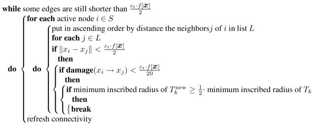
While edge bisection reduces the length of edges in S to be shorter than ct · f[x], node merging tends to lengthen some edges to be at least as long as ct · f[x]. In other words, edge bisection and node merging work in opposition. Because of that opposition, nodes i and j are only merged (Algorithm I.2) if is less than , to avoid “thrashing” where node-merge and edge-bisection operations pointlessly alternate in the same region.
Algorithm I.2.
Node Merge(ct, f[x], S)
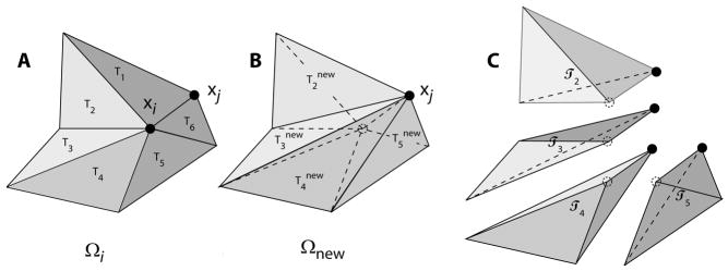
Importantly, edge bisection leaves the geometry exactly unchanged, whereas node merging can cause some surface alteration or “damage” (Figure 20). Since we are focused on a triangulated surface with an imperfect geometry, we accept some damage. Our full definition of damage(xi → xj) is given in [12]. Here we simply state that our metric of damage is the maximum altitude of the swept tetrahedra { } (Figure 20B&C) with respect to new triangles {
}. With damage so defined we forgo any merge that is anticipated to cause a damage exceeding
. For a given node i, there may be one or more neighboring nodes j that produce an acceptable damage estimate, even if some neighboring nodes j would result in unacceptable damage. The new triangulation
(Figure 20) produced by an xi → xj merge depends on which neighbor j is chosen and we only accept a new triangulation if the minimum inscribed radius in
would be at least one-half as big as the minimum inscribed radius of the original triangulation Tk. If the minimum inscribed radius of the original triangulation is especially small, this requirement is tightened further.
Figure 20.
Merging of node i at xi to neighboring node j at xj. A Appearance before merge where neighborhood Ωi of xi consists of N surface triangles Tk. B Appearance after merge where replacement neighborhood Ωnew consists of N–2 new surface triangles
. C Deformation of surface by this merge sweeps out a volume that can be decomposed into N–2 tetrahedra  k
k
Edge swap operations attempt to maximize the minimum vertex angle of a candidate pair of adjacent surface triangles. We repeatedly sweep through candidates in the mesh and perform swaps if the minimum of the six vertex angles is increased by swapping their common edge, provided that the damage to the surface by such a swap is deemed acceptable. (As in the case of node merging, the damage should not exceed and the damage is similarly estimated.)
Refinement and de-refinement of the surface alternates node merging with edge swapping until neither operation changes the mesh, and then ends with edge refinement. This modification of the surface is repeatedly called and alternated with volume-conserving smoothing [?]. After several such cycles, the surface mesh has been suitably processed so that the edge length at a node xi on the surface is roughly ct · f[x].
II. Derivation of Gradient and Hessian of Orthogonality Energy
The following formulas for the gradients of the length and area are useful for our derivations:
| (37) |
and
| (38) |
In addition, the gradient of the volume of tetrahedra in the prism is given in (15). Given these formulas, the gradient of E⊥ in (16) and (17) can be verified in a straightforward manner by applying the chain rule. For the computation of Hessian, we note the following formulas:
| (39) |
| (40) |
and
Most of these formulas are easy to prove except for the gradient and Hessian of ab and at, for which we refer readers to [48]. Using these formulas, we show the derivation for the first three cases of in (19) as follows.
-
Case 1: j = i± (where 1 ≤ j ≤ 3).
(41) where .
-
Case 2: j = i (where 1 ≤ j ≤ 3).
(42) -
Case 3: j = i + 3 (where 4 = j = 6).
(43)
The formulas for in (20) can be proved similarly by symmetry.
References
- 1.Kadirvel R, Ding YH, Dai D, Zakaria H, Robertson AM, Danielson1 MA, Lewis DA, Cloft HJ, Kallmes DF. The influence of hemodynamic forces on biomarkers in the walls of elastase-induced aneurysms in rabbits. Neuroradiology. 2007;49:1041–1053. doi: 10.1007/s00234-007-0295-0. [DOI] [PubMed] [Google Scholar]
- 2.Schirmer CM, Malek AM. Wall shear stress gradient analysis within an idealized stenosis using non-Newtonian flow. Neurosurgery. 2007;61:853–863. doi: 10.1227/01.NEU.0000298915.32248.95. [DOI] [PubMed] [Google Scholar]
- 3.De Backer J, Vos W, Devolder A, Verhulst S, Germonpré P, Wuyts F, Parizel P, De Backer W. Computational fluid dynamics can detect changes in airway resistance in asthmatics after acute bronchodilation. J Biomech. 2007;41:106–113. doi: 10.1016/j.jbiomech.2007.07.009. [DOI] [PubMed] [Google Scholar]
- 4.Kleinstreuer C, Shi H, Zhang Z. Computational analyses of a pressurized metered dose inhaler and a new drug-aerosol targeting methodology. J Aerosol Med. 2007;20(3):294–309. doi: 10.1089/jam.2006.0617. [DOI] [PubMed] [Google Scholar]
- 5.Miao H, Hu YL, et al. Effects of flow patterns on the localization and expression of ve-cadherin at vascular endothelial cell junctions: in vivo and in vitro investigations. J Vasc Res. 2005;42(1):77–89. doi: 10.1159/000083094. [DOI] [PubMed] [Google Scholar]
- 6.Giannoglou GD, Soulis JV, et al. Wall pressure gradient in normal left coronary artery tree. Med Eng Phys. 2005;27(6):455–64. doi: 10.1016/j.medengphy.2004.12.015. [DOI] [PubMed] [Google Scholar]
- 7.Chien S, Li S, et al. Molecular basis of mechanical modulation of endothelial cell migration. Front Biosci. 2005;10:1985–2000. doi: 10.2741/1673. [DOI] [PubMed] [Google Scholar]
- 8.Zarins CK, Taylor CA, Hughes TJR. Finite element modeling of blood flow in arteries. Comput Methods Appl Mech Engrg. 1998;158:155–196. [Google Scholar]
- 9.Longest WP. Comparison of blood particle deposition models for non-parallel flow domains. J Biomech. 2003;36(3):421–430. doi: 10.1016/s0021-9290(02)00434-7. [DOI] [PubMed] [Google Scholar]
- 10.Chiou MC. Particle deposition from natural convection boundary layer flow onto an isothermal vertical cylinder. Acta Mechanica. 1998;129:1619–6937. [Google Scholar]
- 11.Kroger C, Drossinos Y. Particle deposition in a turbulent boundary layer over a large particle size spectrum. J Aerosol Sci. 1997;28:631–632. [Google Scholar]
- 12.Kuprat AP, Einstein DR. An anisotropic scale-invariant unstructured mesh generator suitable for volumetric imaging data. J Comput Phys. 2008 doi: 10.1016/j.jcp.2008.09.030. submitted. [DOI] [PMC free article] [PubMed] [Google Scholar]
- 13.Cignoni P, Ganovelli F, Montani C, Scopigno R. Reconstruction of topologically correct and adaptive trilinear isosurfaces. Computers and Graphics. 2000;24(3):399–418. [Google Scholar]
- 14.Natarajan BK. On generating topologically consistent isosurfaces from uniform samples. Visual Computer. 1994;11(1):52–62. [Google Scholar]
- 15.Nielson GM. On marching cubes. IEEE Transactions on Visualization and Computer Graphics. 2003;9(3):283–97. [Google Scholar]
- 16.Nielson GM. IEEE Visualization. Austin, TX, USA: IEEE Comput. Soc; 2004. Dual marching cubes; pp. 489–96. [Google Scholar]
- 17.Ning P, Bloomenthal J. An evaluation of implicit surface tilers. IEEE Computer Graphics and Applications. 1993;13(6):33–41. [Google Scholar]
- 18.Rocchini C, Cignoni P, Ganovelli F, Montani C, Pingi P, Scopigno R. Marching intersections: an efficient resampling algorithm for surface management. Proceedings International Conference on Shape Modeling and Applications; Genova, Italy. IEEE Computer Society; 2001. pp. 296–305. [Google Scholar]
- 19.Schreiner J, Scheiclegger CE, Silva CT. High-quality extraction of isosurfaces from regular and irregular grids. IEEE Transactions on Visualization and Computer Graphics. 2006;12(5):1205–12. doi: 10.1109/TVCG.2006.149. [DOI] [PubMed] [Google Scholar]
- 20.Treece GM, Prager RW, Gee AH. Regularized marching tetrahedra: Improved iso-surface extraction. Computers and Graphics (Pergamon) 1999;23(4):583–598. [Google Scholar]
- 21.Dietrich CE, Scheidegger CA, Schreiner J, Comba JLD, Nedel LP, Silva CT. Edge transformations for improving mesh quality of marching cubes. IEEE Visualization and Computer Graphics. 2008;14(5):33–41. doi: 10.1109/TVCG.2008.60. [DOI] [PubMed] [Google Scholar]
- 22.Jiao X. Face offsetting: A unified approach for explicit moving interfaces. J Comput Phys. 2007;220:612–625. [Google Scholar]
- 23.Thompson JF, Soni BK. Handbook of Grid Generation. CRC Press; 1999. [Google Scholar]
- 24.Garimella RV, Shephard MS. Boundary layer mesh generation for viscous flow simulations. Int J Numer Meth Engrg. 2000;49:193–218. [Google Scholar]
- 25.Hassan O, Morgan K, Probert EJ, Peraire J. Unstructured tetrahedral mesh generation for three-dimensional viscous flows. Int J Numer Meth Engrg. 1996;39:549–567. [Google Scholar]
- 26.Ito Y, Shih AM, Soni BK, Nakahashi K. Multiple marching direction approach to generate high quality hybrid meshes. AIAA J. 2007;45:162–167. [Google Scholar]
- 27.Kallinderis Y, Ward S. Prismatic grid generation for three-dimensional complex geometries. AIAA J. 1993;31:1850–1856. [Google Scholar]
- 28.Khawaja A, McMorris H, Kallinderis Y. Hybrid grids for viscous flows around complex 3-d geometries including multiple bodies. 1995 AIAA-95-1685. [Google Scholar]
- 29.Pirzadeh S. Unstructured viscous grid generation by advancing-layers method. AIAA J. 1994;32:1735–1737. [Google Scholar]
- 30.Pirzadeh S. Three-dimensional unstructured viscous grids by the advancing-layers methods. AIAA J. 1996;34:43–49. [Google Scholar]
- 31.Wang YL, Murgie S. Proc 15th Int Meshing Roundtable. Springer; 2006. Hybrid mesh generation for viscous flow simulations. [Google Scholar]
- 32.Sharov D, Nakahashi K. Hybrid prismatic/tetrahedral grid generation for viscous flow applications. AIAA J. 1998;36:157–162. [Google Scholar]
- 33.Ito Y, Nakahashi K. Improvements in the reliability and quality of unstructured hybrid mesh generation. Int J Numer Meth Fluids. 2004;45:79–108. [Google Scholar]
- 34.Athanasiadis AN, Deconinck H. A folding/unfolding algorithm for the construction of semi-structured layers in hybrid grid generation. Comput Meth Appl Mech Engrg. 2005;194:5051–5067. [Google Scholar]
- 35.Löhner R, Cebral J. Generation of non-isotropic unstructured grids via directional enrichment. Int J Numer Meth Engrg. 2000;49:219–232. [Google Scholar]
- 36.Aubry Romain, Löhner Rainald. Generation of viscous grids at ridges and corners. Int J Numer Meth Engrg. 2008 to appear. [Google Scholar]
- 37.Sethian JA. Level Set Methods and Fast Marching Methods: Evolving Interfaces in Computational Geometry, Fluid Mechanics, Computer Vision, and Materials Science. Cambridge University Press; 1999. [Google Scholar]
- 38.Sethian JA. Curvature flow and entropy conditions applied to grid generation. J Comput Phys. 1994;115:440–454. [Google Scholar]
- 39.Wang YL, Guibault F, Camarero R. Eikonal equation-based front propagation for arbitrary complex configurations. Int J Numer Meth Engrg. 2008;73:226–247. [Google Scholar]
- 40.Lorensen WE, Cline HE. Marching cubes: A high resolution 3-d surface construction algorithm. Computer Graphics. 1987 July;21(4):163–170. [Google Scholar]
- 41.Newman TS, Yi H. A survey of the marching cubes algorithm. Computers & Graphics. 2006;30:854–879. [Google Scholar]
- 42.Edelsbrunner H. Geometry and Topology for Mesh Generation. Cambridge University Press; 2001. [Google Scholar]
- 43.Cormen TH, Leiserson CE, Rivest RL, Stein C. Introduction to Algorithms. 2. MIT Press; Cambridge, MA: 2001. [Google Scholar]
- 44.Smits B. Efficiency issues for ray tracing. SIGGRAPH ‘05: ACM SIGGRAPH 2005 Courses. 2005:6. http://doi.acm.org/10.1145/1198555.1198745.
- 45.Khamayseh A, Hansen G. Use of the spatial kd-tree in computational physics applications. Commun Comput Phys. 2007;2:545–576. [Google Scholar]
- 46.Jiao X, Zha H. Consistent computation of first- and second-order differential quantities for surface meshes. ACM Solid and Physical Modeling Symposium. 2008 [Google Scholar]
- 47.Baker BB, Copson ET. 3. AMS Chelsea Publishing; 1987. The Mathematical Theory of Huygens’ Principle. [Google Scholar]
- 48.Jiao X, Wang D, Zha H. Simple and effective variational optimization of surface and volume triangulations. 17th International Meshing Roundtable. 2008 to appear. [Google Scholar]
- 49.Heath MT. Scientific Computing: An Introductory Survey. 2. McGraw-Hill; New York: 2002. [Google Scholar]
- 50.Si H. Adaptive tetrahedral mesh generation by constrained Delaunay refinement. Int J Numer Meth Engrg. 2008 http://dx.doi.org/10.1002/nme.2318.
- 51.Shewchuk JR. Tetrahedral mesh generation by Delaunay refinement. 14th Annu Sympos Comput Geom. 1998 [Google Scholar]
- 52.Shewchuk JR. 11th International Meshing Roundtable. Ithaca; New York: 2002. Constrained Delaunay tetrahedralizations and provably good boundary recovery; pp. 193–204. [Google Scholar]
- 53.Shewchuk JR. General-dimensional constrained Delaunay and constrained regular triangulations, i: Combinatorial properties. Discrete & Computational Geometry. 2008;39:580–637. [Google Scholar]
- 54.Amenta N, Bern M. Surface reconstruction by Voronoi filtering. Discr and Comp Geom. 1999;22:481–504. [Google Scholar]
- 55.Amenta N, Bern M, Kamvysselis M. A new voronoi-based surface reconstruction algorithm. Siggraph. 1998:415–421. [Google Scholar]
- 56.Dheeravongkit A, Shimada K. Inverse adaptation of a hex-dominant mesh for large deformation finite element analysis. Comput Aid Des. 2007;39:427–438. [Google Scholar]
- 57.Knupp PM. Achieving finite element mesh quality via optimization of the Jacobian matrix norm and associated quantities. Part II–a framework for volume mesh optimization and the coni. Int J Numer Meth Engrg. 2000;48:1165–1185. [Google Scholar]
- 58.Zhang Y, Bajaj C. Technical report. the University of Texas; Austin: 2004. Finite element meshing for cardiac analysis. Technical Report 04-26. [Google Scholar]
- 59.Zhang Y, Bajaj C, Sohn BS. 3d finite element meshing from imaging data. Computer Methods in Applied Mechanicsand Engineering. 2005;194:5083–5106. doi: 10.1016/j.cma.2004.11.026. [DOI] [PMC free article] [PubMed] [Google Scholar]


