Abstract
Microwave radiometry has been proposed as a viable noninvasive thermometry approach for monitoring subsurface tissue temperatures and potentially controlling power levels of multielement heat applicators during clinical hyperthermia treatments. With the evolution of technology, several analog microwave radiometry devices have been developed for biomedical applications. In this paper, we describe a digital microwave radiometer with built-in electronics for signal processing and automatic self-calibration. Performance of the radiometer with an Archimedean spiral receive antenna is evaluated over a bandwidth of 3.7–4.2GHz in homogeneous and layered water test loads. Controlled laboratory experiments over the range of 30–50°C characterize measurement accuracy, stability, repeatability and penetration depth sensitivity. The ability to sense load temperature through an intervening water coupling bolus of 6mm thickness is also investigated. To assess clinical utility and sensitivity to electromagnetic interference (EMI), experiments are conducted inside standard clinical hyperthermia treatment rooms with no EM shielding. The digital radiometer provided repeatable measurements with 0.075°C resolution and standard deviation of 0.217°C for homogeneous and layered tissue loads at temperatures between 32–45°C. Within the 3.7–4.2GHz band, EM noise rejection was good other than some interference from overhead fluorescent lights in the same room as the radiometer. The system response obtained for ideal water loads suggests that this digital radiometer should be useful for estimating subcutaneous tissue temperatures under a 6mm waterbolus used during clinical hyperthermia treatments. The accuracy and stability data obtained in water test loads of several configurations support our expectation that single band radiometry should be sufficient for sub-surface temperature monitoring and power control of large multielement array superficial hyperthermia applicators.
Keywords: radiometry, microwaves, noninvasive thermometry, hyperthermia
1. Introduction
Microwave radiometry is a spectral based noninvasive temperature sensing technique primarily developed for use in remote sensing applications such as geophysical explorations and radio astronomy (Kenney and McClain, 1964; Schanda, 1976). Over the past three decades, it has also been explored as a complementary technique for detecting cancer (Sterzer, 1987; Carr, 1989; Cheever and Foster, 1992; Mouty et al., 1998; Bardati et al., 1992), monitoring subcutaneous tissue temperature at depths, most notably inside infant brains (Maruyma et al., 2000; Karanasiou et al., 2005; Bardati et al., 2004; Hand et al., 2001), monitoring and control of interstitial microwave antenna (Camart et al., 2000), and superficial microwave sources (Ohba et al., 1995; Stauffer et al., 1999; Jacobsen et al., 2000) during hyperthermia treatments. Like infrared thermography, microwave radiometry relies on black body radiation emitted by lossy objects in the electromagnetic spectrum with the advantage that the penetration depth could be extended to several centimeters by sampling different regions in the microwave frequency spectrum. In medial applications of microwave radiometry, the brightness temperature measured by the radiometer given by (Jacobsen and Stauffer, 2007),
| (1) |
is a function of the electromagnetic thermal noise, T(r⃗) emitted by the lossy body and the weighted near-field radiation pattern W(fc, r⃗) of the receiving antenna at location r⃗a . In (1), r⃗ is the spatial variable inside the 3D volume (V) of the lossy body that confines the near-field radiation pattern of the antenna.
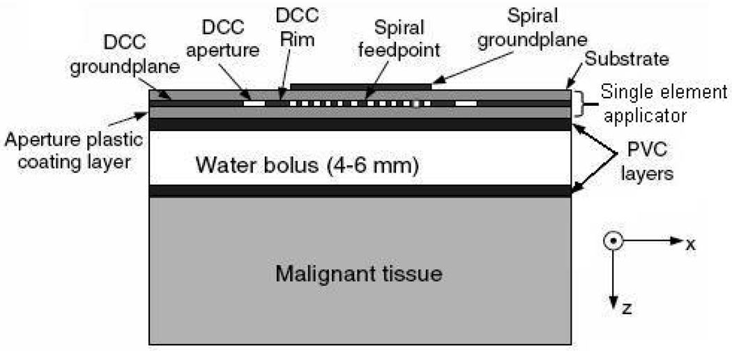
A number of randomized clinical trials of thermoradiotherapy have been reported (Jones et al., 2005; Overgaard et al., 1995; Sneed et al., 1998b; Sneed et al., 1998a; Valdagni and Amichetti, 1994; Vernon, 1994) which demonstrate the efficacy of local hyperthermia as an adjuvant to radiation and chemotherapy of cancer. In a typical hyperthermia treatment, energy radiated by the heating device (microwaves or ultrasound) is coupled to the target tissue via a stable temperature controlled waterbolus. The effectiveness of hyperthermia treatment relies on the ability to deliver relatively uniform heating to maintain the target tissue within a narrow therapeutic window (e.g. 42–44°C) while minimizing heating of adjacent healthy tissue. Thus, satisfactory performance of hyperthermia applicators requires real-time thermometry to closely monitor the tissue temperature distribution for effective feedback power control of large multielement heat applicators. Current thermometry techniques involve either multiple single sensor fiberoptic or high resistance lead thermistor temperature probes taped to the skin surface or pulled back and forth inside hollow thermal mapping catheters placed either on the skin surface or at shallow depth to characterize superficial tissue temperatures (Jacobsen and Stauffer, 2007). Potentially high resolution noninvasive temperature distribution provided by sensing techniques such as magnetic resonance imaging, magnetic resonance spectroscopy, and infrared thermography are either expensive or difficult to incorporate with superficial hyperthermia heating devices. An alternate noninvasive thermometry technique includes microwave radiometry which is both relatively inexpensive and easy to integrate with superficial microwave array applicators (Jacobsen et al., 1998; Stauffer et al., 1999). Due to the inverse relationship between the operating frequency and electromagnetic penetration depth, lower microwave frequencies are used for sensing deeper into tissue and higher frequencies are better suited for superficial temperature monitoring during hyperthermia treatments. Several studies from this group have focused on incorporating noninvasive microwave radiometry with dual concentric conductor (DCC) (Jacobsen and Stauffer) hyperthermia applicator arrays developed to treat large area superficial tissue disease over highly contoured areas of the human body. Several key design issues such as the receive antenna (Jacobsen and Stauffer, 2001; Rolfsnes, 2002; Rolfsnes et al., 2004), development of a dual purpose heating and temperature monitoring flexible microstrip array applicator (Jacobsen et al., 1998; Stauffer et al., 1999; Jacobsen et al., 2000; Maccarini et al., 2005), operating frequency (Jacobsen and Stauffer, 2002a; Jacobsen and Stauffer, 2003; Jacobsen and Stauffer, 2007), and temperature profile estimation (Jacobsen and Stauffer, 2002b; Jacobsen and Stauffer, 2003) were systematically studied using numerical simulations and experimental data acquired using an analog radiometry device. Figure 1 shows a single element of the conformal DCC applicator array with radiometric receive antenna used in the hyperthermia treatment of superficial tissue disease. Radiometric temperature measured through an intervening waterbolus is used to estimate the maximum temperature inside the target tissue (≤2cm) which also includes the skin. Theoretical analyses of a single band microwave radiometry for superficial tissue temperature monitoring showed marginal change in the estimated maximum tissue temperature for realistic deviation in tissue thermal and dielectric properties, and significant change for variations in the thickness and temperature of the coupling waterbolus (Jacobsen and Stauffer, 2007). Automated feedback of the volume average tissue temperature under each heating element would enable to control the power level radiated by the array applicator to deliver a more uniform heating of large-area disease.
Figure 1.
Illustration of a single DCC element with radiometric receive antenna used in the hyperthermia treatment of superficial tissue disease.
Prior theoretical foundation and volume average temperature measurements provided the motivation to build a digital microwave radiometry device with internal calibration fixture and electronics for automated calibration, signal processing, and temperature display. In this paper, we characterize the performance of the prototype digital microwave radiometer over 3.7–4.2 GHz frequency range using a test load with known temperature distribution and demonstrate the ability to sense the load temperature through a 6mm thick waterbolus. A brief description of the digital radiometer is presented in section 2. Experiments conducted to evaluate measurement accuracy, system stability, antenna depth sensing and sensitivity to electromagnetic interference (EMI) over 3.7–4.2 GHz frequency range are explained in section 2. The experimental results are presented in section 3 and the implications of this performance are discussed in section 4.
2. Methods
2.1. Digital Radiometer
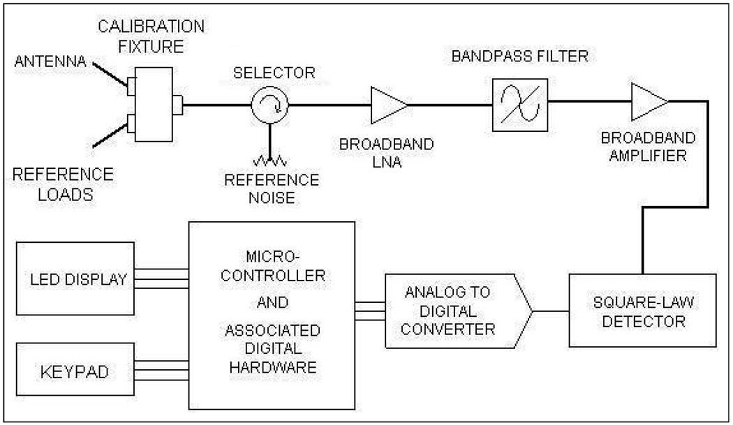
A basic microwave radiometer consists of the following three elements: an antenna to gather the (thermal) radiation emitted by a (tissue) volume at temperature higher than the background, a cable to transmit the extremely low power thermal radiation to the radiometer, and the internal electronics to convert the microwave noise signal to an equivalent volume averaged temperature. Figure 2 shows the schematic block diagram of the digital microwave radiometer developed and fabricated by MMTC Inc. (Princeton, NJ, USA) under SBIR grants from the National Institute of Health. The calibration fixture in figure 2 was designed to calibrate the whole system using internal reference loads (which takes 21s) or perform partial calibration to individually compensate for thermal noise pickup and signal attenuation associated with the cable, and antenna reflection coefficient (which takes 7s). The calibration fixture consists of two reference loads whose temperatures are measured using thermistors calibrated to ±0.1°C. The radiometric energy measured from the reference loads at known temperature is used to calibrate the temperature measured by the receiving antenna. The microwave signal from the receive antenna is selectively sampled using a narrow band pass filter (500 MHz) centered about the frequency of interest (3.7–4.2 GHz) and is finally fed to the microcontroller for further processing. The microcontroller unit converts the received energy radiated by the lossy body into a calibrated temperature using reference thermal noise source and displays the volume averaged effective temperature to the user in real time. A five-digit LED display and press-button keypad provides the user interface to the microcontroller. Once calibrated, the digital radiometer reads the load temperatures faster than conventional analog radiometers as it employs no feedback loops. The 3.7–4.2 GHz frequency band reserved by the Federal Communications Commission for downlink satellite service was intentionally used for the digital microwave radiometer to avoid interference from terrestrial radio services.
Figure 2.
Basic block diagram of MMTC microwave radiometer with microcontroller and inbuilt digital electronics.
2.2. Radiometer Characterization
Initial efforts that studied the impedance characteristics and usable bandwidths of numerous receive antenna structures for microwave radiometry indicated Archimedean spiral antennas with 3–5 cm diameter to possess the largest bandwidth with usable impedance match to tissue over 800 MHz to 4.5 GHz (Jacobsen and Stauffer, 2001; Jacobsen and Stauffer, 2002a; Jacobsen and Stauffer, 2007). The PCB spiral antennas also produced quite remarkable accuracy of 0.2°C for homogenous load at known temperature (Jacobsen and Stauffer, 2001). Earlier investigations on microwave radiometry antenna design were used to choose a PCB Archimedean spiral antenna with 4.5 cm diameter for radiometer brightness temperature measurement over 3.7–4.2 GHZ frequency band. Performance of the digital radiometer using a 4.5 cm diameter Archimedean Spiral antenna was studied using homogeneous test loads at a prior known temperature. The test load used in this study is deionized water (18Mega Ohms resistivity) inside stabilized temperature regulated waterbaths at known temperatures. The load temperature inside the waterbaths was measured using type T thermocouples (Sensortek Inc., Clifton, New Jersey) connected to probe selector (Bailey Instrument Co., Saddle Brook, N.J) linked to a BAT-10 thermometer (Physitemp Inc., Clifton, New Jersey) with 0.1°C resolution over −100 to +100°C. Homogeneous temperature was maintained inside the test load by circulating deionized water through heat exchange coils.
The test load maintained at known temperature with stable thermal and dielectric properties facilitates a controlled and repeatable experimental setup to characterize the response of the digital microwave radiometry system over 3.7–4.2 GHz frequency band. The brightness temperature measurements obtained for the standard load could be used to characterize and potentially calibrate the system for use with unknown heterogeneous load such as the tissue. Thus, radiometric temperature measurements obtained for simple test loads in several configurations were used to study i) system response to step change in thermal load, ii) system linearity, iii) temperature measurement at depth, iv) temperature measurement through an intervening waterbolus at different temperature, and v) calibration stability of the system over 3.7–4.2 GHz frequency band. The very low power levels of EM thermal noise (~10−12 Watts) gathered for brightness temperature measurement renders the microwave radiometer vulnerable to EMI from surrounding electrical equipment, especially computers and overhead fluorescent lights which are particularly noisy from an electromagnetic radiation standpoint. Experiments were conducted using the test load to evaluate the sensitivity of the radiometric temperature measurements to EMI both inside an electromagnetic shield room, and subsequently in a regular unshielded clinical hyperthermia treatment room. The radiometric brightness temperature measurements of the test load at steady state were used to quantify the accuracy of the 3.7–4.2 GHz digital microwave radiometer system.
2.2.1. System Response to Step Input
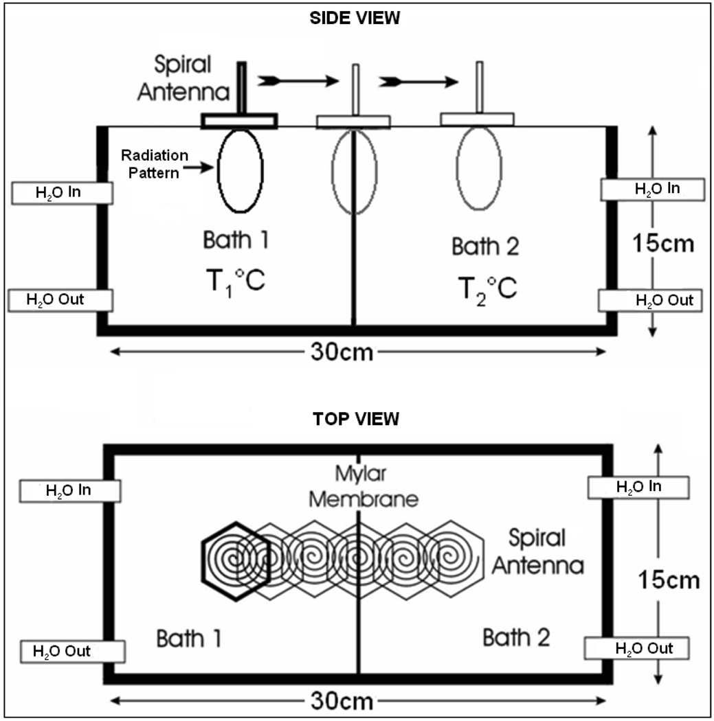
The volume average temperature measured by the radiometer given by (1) depends on the near field radiation pattern of the radiometer receive antenna about the center frequency, fc. The field of view of the radiometer receive antenna on the spatial volume average temperature measurements was studied using the experimental setup in figure 3. In figure 3, a steep thermal gradient was maintained across a 15×15×30 cm3 plexiglass dual chamber waterbath using a 75µm thick Mylar film with low thermal conductivity (0.002 W/cm/K) in combination with vigorously circulated temperature regulated water in each of the two chambers. Homogeneous temperatures were measured 2–3 mm away from the Mylar separation within the individual water baths. The radiometer brightness temperatures measured for a predetermined step change in thermal load across the dual chamber waterbath were used to study the system response and the sensing volume of the 4.5 cm diameter Archimedean spiral antenna. The dimension of the water baths was chosen large enough to confine the 3D sensing volume of the receive antenna inside the test load (deionized water) at the center frequency. The temperature inside the waterbaths was controlled by vigorously circulating the deionized water load through external temperature controlled heat exchange coils using Tygon tubing (Cole-Parmer Instrument Company, Vernon Hills, IL). The air trapped inside the waterbath was continuously removed by circulating the temperature controlled water through inverted water traps (Balston, Parker Hannifin Corporation, Harverhill, MA). Prior to measurement, temperature distribution measured using thermocouples were used to ensure thermal homogeneity of the test load. The spiral antenna was wrapped in 10µm thick low density polyethylene film to keep cable connections dry when in contact with deionized water and mounted on a computer controlled two axis positioning device. The radiometer was calibrated with the film encased antenna in contact with the waterbath surface. After calibration, the receive antenna in contact the waterbath surface was mechanically scanned using Labview 8.2.1 (National Instruments Corporation, Austin, TX) and radiometer temperature measurements were recorded at 5mm intervals.
Figure 3.
Experimental setup of the receive antenna mounted above the dual chamber waterbath with the test load maintained at stable uniform temperature inside the individual chambers.
2.2.2. System Linearity
The dual chamber water bath setup in figure 3 was used to measure load temperature over a wide range that includes the typical hyperthermia therapy temperatures. The temperature of the test load was increased from starting at 30°C to about 50°C and radiometer measurements over 3.7–4.2 GHz frequency band were recorded for each temperature setting after uniform temperature distribution was achieved inside the bath. Thermal homogeneity of the temperature controlled test loads was verified by recording thermocouple temperatures at multiple locations inside the chamber. Radiometer measurements obtained by directly sensing the steady state temperature of homogeneous test load were compared with the corresponding thermocouple readings to characterize the linearity of the radiometer over 30–50°C.
2.2.3. Temperature Measurement at Depth
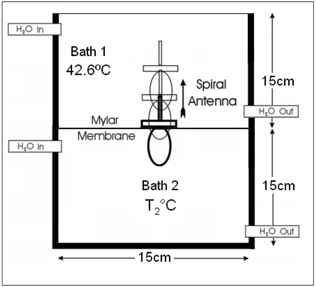
Experiments were conducted to quantify the penetration depth of the receive antenna over 3.7–4.2 GHz inside the test load at known uniform temperature. Figure 4 illustrates the experimental setup that consists of a vertically stacked plexiglass waterbath separated by an insulating layer of 75 µm thick Mylar film. The dimension of the individual chamber in figure 4 is 15×15×15 cm3, which is bigger than the 3D sensing volume of the receive antenna inside the test load. The chambers were filled with deionized water that was circulated through external heat exchange coils to maintain uniform temperature inside the water baths. Steady state temperatures inside the water chambers were measured using thermocouples as described in Section 2.2.1. Needle thermocouples inserted through the water outlet tubing were used to measure load temperature inside the closed water chamber at the bottom. The temperature inside the upper water bath was maintained at 42.6°C, while the bottom chamber was maintained at 37°C and later at 44.5°C during the experiment. The Archimedean spiral antenna wrapped inside a 10 µm thick low density polyethylene film was held inside the top water chamber in contact with the Mylar film. Radiometer temperature measurements were recorded as the antenna was gradually moved away from the Mylar film at 5mm interval using the motion control system. Calibration was performed for each temperature measurement to compensate for the change in cable reflection coefficient arising due to the difference in the coaxial cable length inside the top water chamber at each measurement position.
Figure 4.
Radiometer receive antenna inside the vertically stacked dual chamber waterbath with the load maintained at known uniform temperature.
2.2.4. Temperature measurement through waterbolus
During hyperthermia treatment, heat delivered to the tissue is coupled through a waterbolus that is usually maintained at 42–43°C. The thickness and temperature inside the waterbolus were previously observed to have significant influence on the radiometer temperature measurements (Jacobsen and Stauffer, 2007). Thus, experiment was conducted to study the feasibility to measure the test load temperature through an intervening waterbolus with typical dimension and bolus water temperature as in superficial hyperthermia treatments (Neuman et al., 2002). The waterbolus used in this study is a 200µm thick polyurethane (Deerfield Urethane, South Deerfield MA) bag with a 20 pores per inch polyurethane filter foam (Hibco Plastics, Yadkinville NC) that helps to maintain a uniform layer of deionized water when stretched across the tissue surface. The average thickness of the bolus bag stretched across the waterbath surface was maintained at 6mm. The water temperature inside the bolus bag was maintained at 43°C and the air trapped inside the bolus was removed using an inverted water trap filter as explained in section 2.2.1. The temperature of the test load was gradually increased and radiometer temperature measurements were recorded for varying steady state load temperatures through the 6mm thick waterbolus with the spiral receive antenna flush mounted on the bolus bag. For each temperature setting, the test load inside the bottom chamber was circulated for 30 minutes to attain uniform thermocouple temperature measurements at multiple points inside the chamber.
2.2.5. Calibration Stability
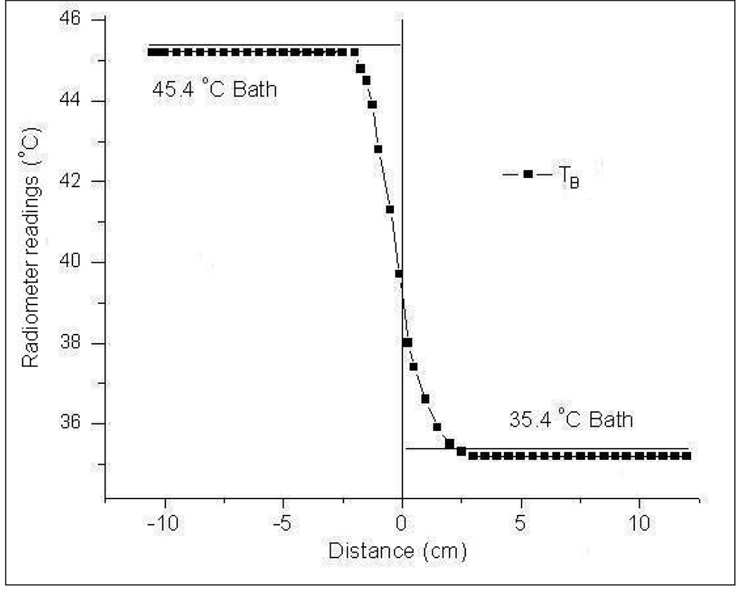
In the dual mode conformal microstrip array (CMA) applicator, the DCC slot antenna is intermittently switched off to gather thermal radiation emitted by the subcutaneous tissue using the passive Archimedean spiral receive antenna. It is important to maintain a short down time for the radiating DCC elements to avoid heat loss inside the target tissue during hyperthermia treatment. This necessitates a radiometry system with short integration time and minimal calibration drift that can be compensated at few predetermined intervals during a typical 60 minute hyperthermia treatment. The calibration stability of the digital radiometer was investigated by measuring drift in brightness temperature measurements with time. The dual chamber waterbath with steep thermal gradient of 10°C across the Mylar film was used in this experiment. The deionized water inside the dual chamber waterbath was maintained at 45.4 and 35.4°C steady state temperatures. Radiometer measurements of the test load were acquired starting with a one time full system calibration above the 45.4°C waterbath and scanning across the test load. To assess the temporal drift in calibration, measurements were acquired over a wider spatial extent from +12 to −12cm across the Mylar film at 5mm intervals.
2.2.6. Susceptibility to EMI
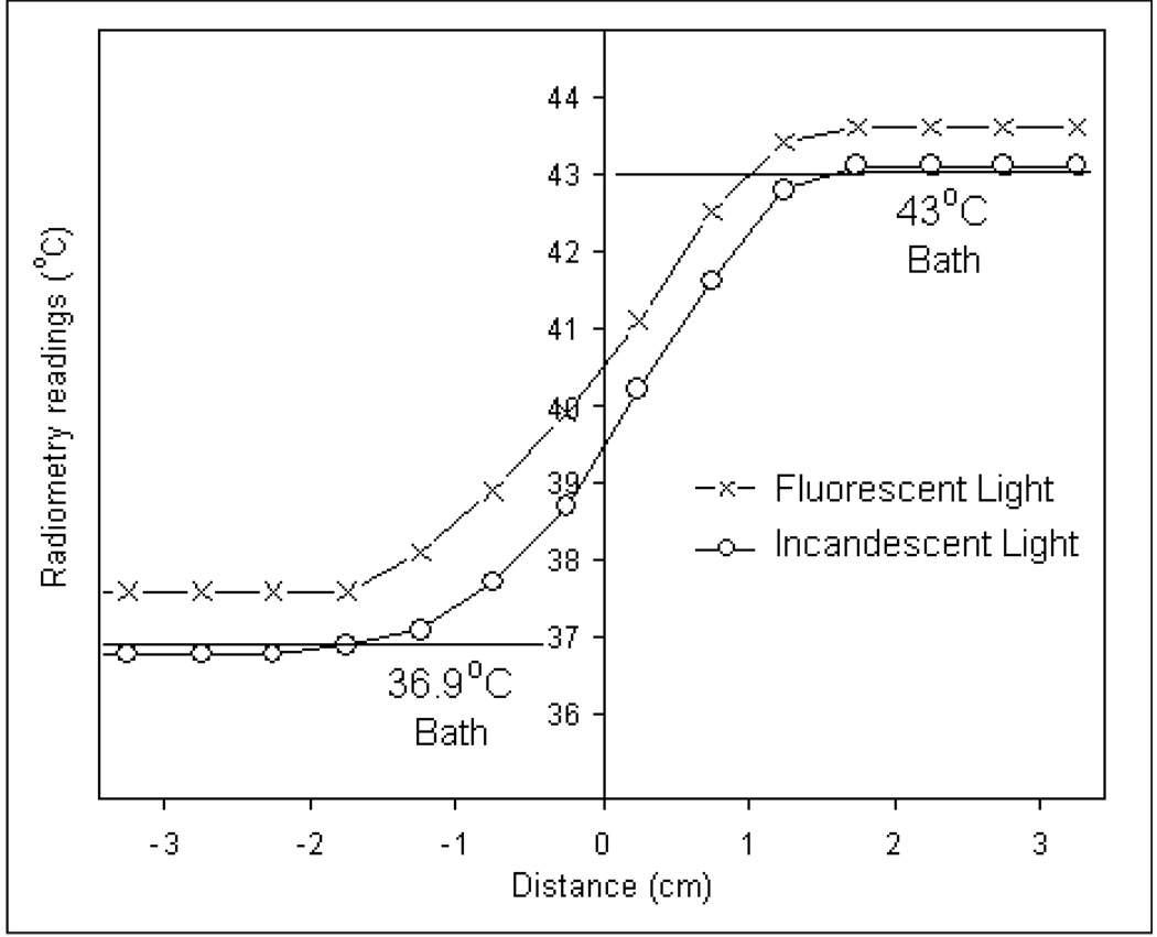
The above experiments were performed in a controlled environment with EM shielding and incandescent light to prevent interference from external EM noise sources. Subsequently, experiments were repeated to study the susceptibility of our 3.7–4.2 GHz digital radiometer to EMI by recording radiometer brightness temperature of the test load in the presence of fluorescent light inside an EM shield room as well as in a standard hyperthermia treatment room without EM shielding. The test loads inside the dual chamber water bath were maintained at steady state temperatures of 36.9 and 43°C respectively ― approximately a 6°C temperature gradient across the insulating Mylar film. The spiral antenna was scanned above the waterbaths and radiometer measurements were recorded after full system calibration at each measurement location. Radiometer temperatures taken inside the EM shield room were compared with thermocouple readings inside the waterbaths to study the influence of the noise radiated by the fluorescent lights.
Since a requirement to have EM shielding could potentially restrict the clinical utility of microwave radiometers for tissue temperature monitoring, we assessed performance of the digital radiometer inside standard unshielded clinical hyperthermia treatment rooms at Duke University Medical Center. Steady state temperature of the test load was measured over 30–45°C using the 4.5cm diameter Archimedean spiral receive antenna. Measurements taken inside hyperthermia treatment rooms were used to characterize the effect of background EMI in the radiometer operating frequency band of 3.7–4.2 GHz. Additional measurements were also taken inside one of the treatment rooms with the experimental setup beneath the MA100 (BSD Medical, Salt Lake City, UT, USA) waveguide applicator connected to the BSD superficial hyperthermia treatment system. Radiometer measurements of the test load at steady state temperature were recorded with the applicator radiating 25 Watts into the test load.
2.2.7. Measurement Accuracy
Radiometer temperature measurements acquired for several configurations of the test load at steady state were used to quantify the measurement accuracy of our 3.7–4.2 GHz digital radiometer over the clinical hyperthermia temperature range. A least squares data fit of the form,
| (2) |
obtained for the radiometer brightness measurements (TB) of the homogeneous test load over 32–45°C was used to quantify the radiometer measurement error,
| (3) |
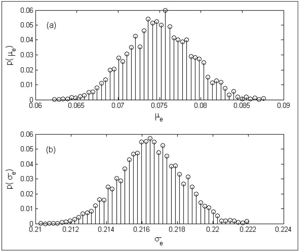
In (2), the slope, m and the temperature deviation, ΔT yields a linear fit between the radiometer brightness temperature measurement (TB) and the steady state load temperature (Tload). Several realizations of the radiometer measurements obtained using (2) for load temperatures recorded over 32–45°C were used to characterize the mean (μe) and standard deviation (σe) of the measurement error, e . The probability distributions, p(μe) and p(σe) for the homogeneous test load were used to quantify the measurement accuracy of the digital radiometry system.
3. Results
3.1. System Response to Step Input
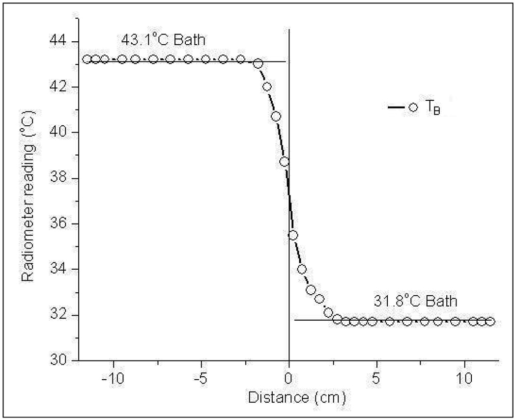
Figure 5 shows the radiometer temperature measurements of the dual chamber waterbath maintained at 43.1°C and 31.8°C steady state temperatures. The S-shaped response for a step change in load temperature across the Mylar separation is due to the finite sensing volume of the Archimedean spiral antenna (Jacobsen et al., 2000; Jacobsen and Stauffer, 2001). Near the Mylar separation, the near field radiation zone of the Archimedean spiral antenna spans both water baths. Thus the radiometer brightness temperature yields a volume weighted average of the steady state temperatures of the test load inside both chambers. Away from the gradient, the antenna gathers thermal noise emitted by the homogeneous test load and measures temperature close to the true load temperature; 43.2°C or 31.7°C respectively for the 43.1°C and 31.8°C waterbaths.
Figure 5.
Radiometer measurements of the homogeneous dual chamber test load with steep temperature gradient across the Mylar film separation.
3.2. System Linearity
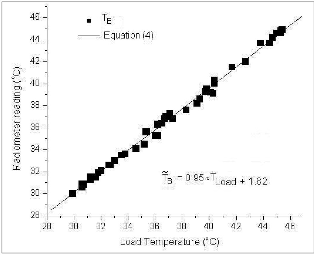
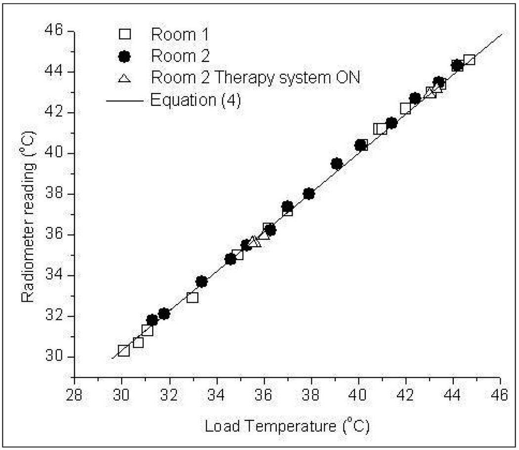
Figure 6 presents the radiometer temperature measurements (TB) over 3.7–4.2 GHz frequency band for varying steady state load temperatures (Tload). The load temperature in figure 6 corresponds to the thermocouple measurement of the test load at steady state. The maximum and minimum deviations of TB from Tload in figure 6 were observed to be +0.6°C and −0.3°C respectively. A least squares first order polynomial fit of the measurements yielded the expression,
| (4) |
Figure 6.
Radiometer measurements as a function of homogeneous water load temperature over 3.7–4.2 GHz frequency band.
Figure 6 and the superimposed Eqn (4) demonstrate the linear response of the 3.7–4.2GHz digital radiometer over 30–50°C for the homogeneous test load at known temperature.
3.3. Temperature Measurement at Depth
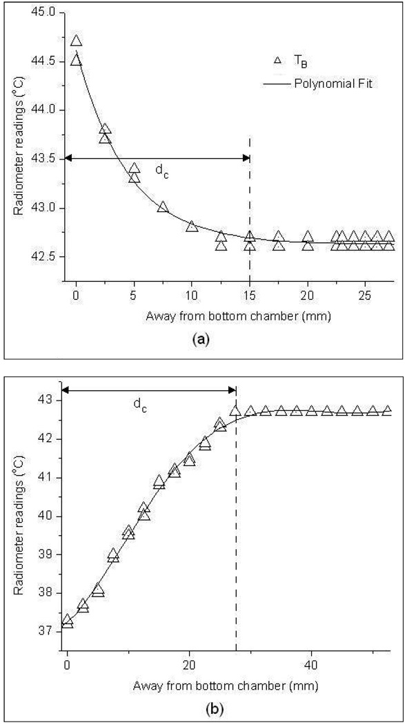
Figure 7 shows the radiometer temperature measurements obtained for the vertically stacked waterbath setup in figure 4 as the receive antenna immersed inside the 42.6°C upper waterbath was moved away from the Mylar separation. Measurements in figure 7(a)–(b) were taken with the load inside the bottom chamber at 44.5 °C and 37°C steady state temperatures respectively. At 0mm distance from the Mylar surface, the antenna listens directly into the lower bath and accurately measures the temperature of the bottom waterbath. Moving away from the Mylar film, the antenna gathers increasing thermal radiation from the upper bath as well as decreasing information from the lower bath, yielding a volume weighted average of both load temperatures. After a critical distance, dc away from the bottom chamber, the sensing volume (near field radiation pattern) of the receive antenna is almost entirely confined to the top chamber and the radiometer reads the upper load temperature. This phenomenon is clearly demonstrated in figure 7(a)–(b). The variation in radiometer temperature measurements, TB in figure 7a–b is due to the variability in the data collected at different instances. The distance, dc was measured to be 1.5 cm and 2.8 cm respectively for the graph in figures 7a and 7b. The distance dc is larger for the 37°C bottom chamber due to the large difference in temperature, |ΔT|=5.6°C between the two water baths.
Figure 7.
Radiometer brightness temperature measurements taken inside the 42.6°C upper waterbath as a function of distance from the bottom test load at a) 45°C and b) 37°C steady state temperatures.
3.4. Temperature Measurement through waterbolus
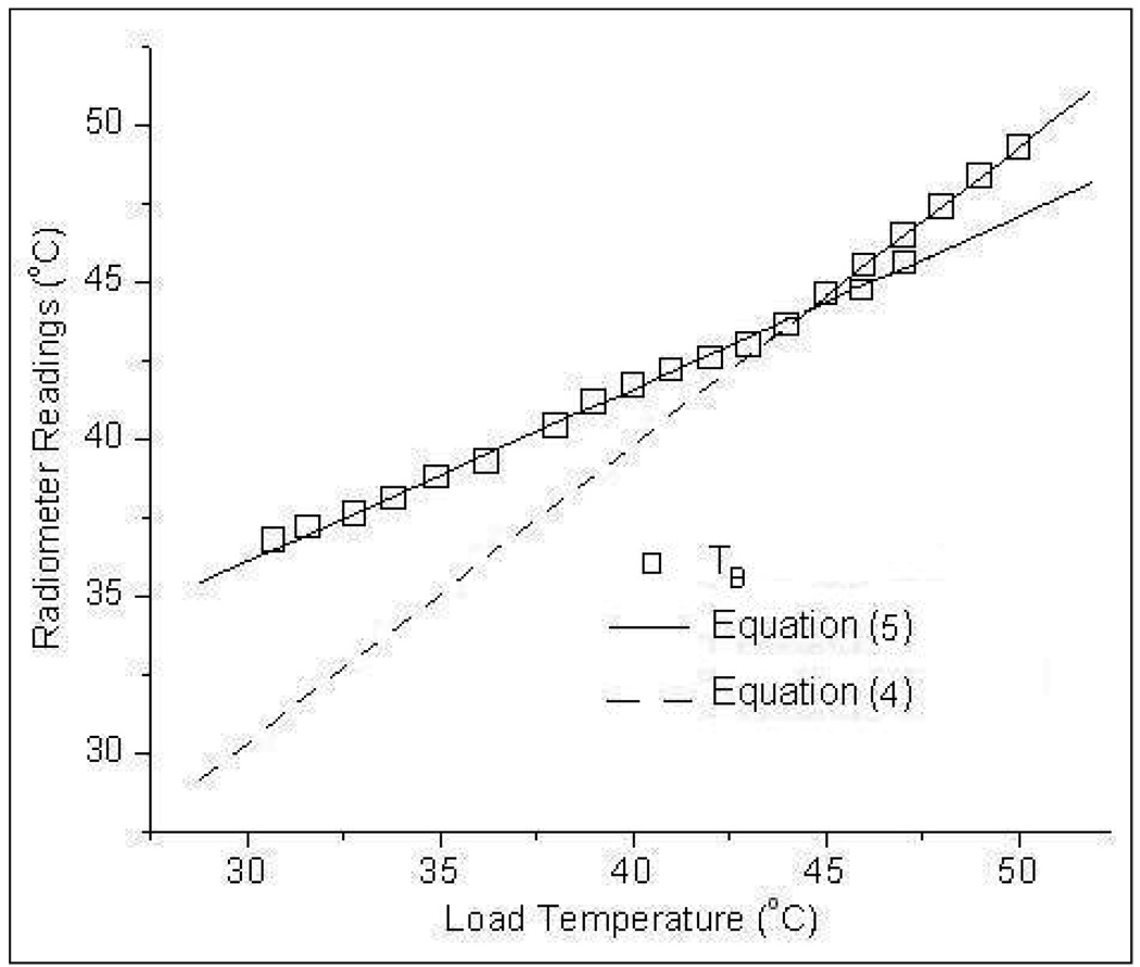
Figure 8 shows the radiometer temperature measurements obtained with the receive antenna sensing through a 6mm thick waterbolus layer maintained at 43°C. From figure 8, it is evident that the radiometer measurement error decreases as the load approaches the bolus temperature. A least squares data fit of the temperature measurements, TB in figure 8 yielded,
| (5) |
Figure 8.
Radiometer brightness temperature measurements of the homogeneous test load with the spiral receive antenna sensing through a 6mm thick water bolus layer maintained at 43°C.
Equation (4) obtained using the direct measurement of the homogeneous water load is superimposed on figure 8 for comparison. Comparison of the trend lines in figure 8 shows the influence of the water bolus on the radiometer temperature measurements. It should be noted that the radiometer measurements of the homogeneous test load in figure 8 depend on the bolus thickness and a different slope and offset would be obtained for other thickness and temperature of the waterbolus.
3.5. Calibration Stability
Figure 9 shows the radiometer temperature measurements obtained over 20 minute time duration as the antenna was scanned above the test load from −12cm to +12cm across the Mylar film. The radiometer temperature measurements for a step change in thermal load shown in figure 9 were obtained with the digital radiometer calibrated once at the beginning above the 45.4°C test load. Even with a single system calibration performed at the beginning of the scan, stable readings were obtained with an accuracy of 0.2°C; reading 45.2°C and 35.2°C respectively above the water baths at 45.4°C and 35.4°C. Stable radiometer temperature measurements over a 20 minute time period in figure 9 indicate stable system calibration which can be used in dual mode for subcutaneous tissue temperature monitoring during hyperthermia treatment (Jacobsen et al., 2000).
Figure 9.
Radiometer brightness temperature measurements across the dual chamber waterbath load following a single system calibration at the beginning of the measurement series.
3.6. Susceptibility to EMI
Unlike incandescent bulbs, fluorescent light emits thermal radiation over a wider electromagnetic spectrum which also includes the 3.7–4.2 GHz operating frequency of the digital radiometer. Figure 10 shows the 3.7–4.2 GHz radiometer temperature measurements of the homogeneous test load inside temperature regulated waterbath taken in an EM shield room with fluorescent lights on. Radiometer measurements taken inside the EM shield room with incandescent lighting is superimposed on figure 10 for analysis. Comparison of the radiometer temperature measurements in figure 10 with true bath temperatures reveals the influence of in-band EM noise from the fluorescent lights over 3.7–4.2 GHz frequency band. Despite a full system calibration at each antenna position, the radiometer overestimated the load temperature by 0.7°C for the 36.9°C load and 0.6°C for 43°C load.
Figure 10.
Radiometer sensitivity to EMI over 3.7–4.2 GHz frequency band for a step change in temperature across the test load taken inside an EM shield room illuminated by fluorescent (-x-) and incandescent (-o-) lights
Figure 11 shows the 3.7–4.2 GHz radiometer temperature measurements of the homogeneous water load for varying steady temperatures taken inside unshielded clinical hyperthermia treatment rooms illuminated with incandescent light. The response shown in figure 11 is in good agreement with data obtained from measurements taken inside a controlled environment with EM shielding as quantified by Eqn (4). The close agreement between radiometer measurements in shielded (Eqn 4) and normal unshielded rooms lit with incandescent light implies that the high frequency band digital radiometer should be useful in normal unshielded rooms such as those used for superficial hyperthermia treatments at the Duke University Medical Center.
Figure 11.
Radiometer measurements of the test load inside unshielded clinical hyperthermia treatment rooms with fluorescent lights off.
3.7. Measurement Accuracy
Several realizations of the radiometer measurement obtained using Eqn (4) were used to quantify the accuracy of the digital radiometer over 3.7–4.2 GHz frequency band. Figure 12 shows the probability distribution functions, p(μe) and p(σe)of the measurement error, e over 32–45°C. The graphs in figure 12 indicate the measurement error to be centered about 0.075°C with a standard deviation of 0.217°C. Measurement resolution of 0.075°C with an error defined by a standard deviation of 0.22°C is in agreement with the earlier investigations.
Figure 12.
Probability denisty functions of the radiometer measurement error (e) for homogeneous test load obtained using Eqn (4); a) p(μe); b) p(σe).
4. Discussion
This paper presents the performance of a 3.7–4.2 GHz digital microwave radiometer system intended for noninvasive measurements of volume averaged temperature of a biological tissue load with or without an intervening water coupling bolus. Performance of the radiometer in a 500 MHz measurement band from 3.7–4.2 GHz was evaluated using stable temperature controlled deionized water as the test load. The S-shaped response in figure 5 across the Mylar separation clearly demonstrates the domain of influence of the 4.5 cm diameter Archimedean spiral antenna on the spatial resolution of the radiometric temperature measurements. Away from the Mylar separation, the radiation pattern of the spiral antenna is confined to the test load and the radiometer measured 43.2°C or 31.7°C respectively for the 43.1°C and 31.8°C water baths. The radiometer temperature measurements in figure 6 for a homogeneous test load indicate the linearity of the system response over 30–50°C that includes the therapeutic temperature range of typical clinical hyperthermia treatments.
Radiometer temperature measurements at depth over 3.7–4.2 GHz frequency band in figure 7a–b clearly indicate our ability to sense an object at different temperature at depth. However, the sensitivity of the radiometer with depth clearly depends on ΔT - the magnitude of the difference between the object’s and intervening media temperatures. The weighted volume averaging process employed by the receiving antenna masks contributions from volumes that are farther from the receiving antenna with smaller temperature gradient. Thus in figure 7b, the lower bath at 37°C with |ΔT|=5.6°C was detectable at a farther distance from the Mylar film than the 45°C lower chamber with a |ΔT|=1.9°C. The graph in figure 7b implies that the digital radiometer operating over the 3.7–4.2 GHz band can detect a 37°C (cold) thermal zone as deep as dc=2.8cm, and a hot spot (45°C) as deep as 1.5cm in a 42.6°C background. In superficial hyperthermia, specific absorption rate (SAR) patterns delivered by the multielement array applicators fall off rapidly with depth and penetrate only few centimeters beneath the tissue surface (Jacobsen and Stauffer, 2001; Jacobsen and Stauffer, 2003). The radiometer sensitivity to a maximum depth of 2.8 cm for this practical temperature gradient is more than adequate to cover the extent of superficial tissue disease typically 5–15mm beneath the tissue surface including the skin that are most often treated with superficial microwave hyperthermia treatments (Rossetto et al., 2000). Again with a goal to mimic actual clinical treatment configurations, experiments were conducted to sense the load temperature beneath a 6mm thick water coupling bolus maintained at a constant 43°C. The temperature measurements in figure 8 demonstrate our ability to sense temperature on the far side of a waterbolus using the 3.7–4.2 GHz digital microwave radiometer. As a practical measure, it should be noted that our ability to measure temperature through an intervening waterbolus depends on bolus thickness and water temperature (Jacobsen and Stauffer, 2007). If the bolus thickness were to increase substantially, the slope of the measurements plotted in figure 8 would approach zero and the radiometer would measure only bolus temperature. Thus, for a receive antenna operating over a given frequency range, the depth of penetration inside the tissue could be significantly altered by the thickness of the 43°C waterbolus. The bolus thickness used in the experiment was selected based on (Gelvich and Mazokhin, 2000; Neuman et al., 2002) and the preferred bolus thickness for 915 MHz multi-antenna array applicators (Rossetto et al., 2000).
The radiometer temperature measurements of the homogeneous test load in figure 9 taken over a 20 minute period demonstrated excellent calibration stability with an accuracy of 0.2°C; reading 45.2°C and 35.2°C respectively above the water baths at 45.4°C and 35.4°C. The accuracy of the radiometer temperature measurements obtained over 20 min after single system calibration is similar to the measurements in figure 4 obtained following repeated system calibrations. The average time durations for full system calibration and partial calibration (only cable loss and antenna reflection coefficient) were measured to be 21 and 7s respectively. Comparison of the radiometer measurements in figure 5 and figure 9 indicate that partial system calibration at predetermined intervals could be used to obtain fast and stable temperature measurements over long time periods with short down time for the radiating DCC elements during a typical 60 minute hyperthermia treatment.
Experiments conducted in the presence of EMI sources such as fluorescent lights revealed the susceptibility of the digital radiometer to in-band thermal noise over 3.2–4.7 GHz frequency band. Figure 10 illustrates the influence of the wide band thermal noise emitted by the fluorescent light on the radiometric temperature measurements. The measurement error in the presence of fluorescent lights was observed to increase with increase in load temperature. However, measurements in figure 11 obtained inside a standard hyperthermia treatment room without EM shielding and in the presence of incandescent light only indicated a high correlation with those obtained inside an EM shield room. The good agreement between measurements in figure 11 with Eqn (4) indicates low EMI over the 3.7–4.2 GHz frequency range when operated inside unshielded clinical treatment rooms, even with 915 MHz waveguide applicator radiating at 25 Watts. This implies potential utility of the digital microwave radiometer for noninvasive superficial tissue thermometry in a standard hyperthermia treatment facility.
Statistical analysis of the 3.7–4.2 GHz digital radiometer temperature measurements of the homogeneous test load over 32–45°C indicates the measurement accuracy of the radiometry system to be μ±σ=0.075°0.217°C. The resolution of the digital radiometer is in agreement with the earlier investigations. It should be noted that the maximum time duration between successive calibrations is less than 20 minutes for the radiometer measurements used in deriving Eqn (4). Thus the above statistics might vary for measurements obtained with longer duration between successive calibrations. The 20 min duration between successive calibrations is a realistic time interval for a typical 60 minute hyperthermia treatment using the dual mode CMA applicator (Jacobsen et al., 2000).
The clinical application that motivated the development of this digital radiometer is the need to monitor superficial tissue temperatures for feedback power control of multielement array microwave applicators that are used for hyperthermia treatments of chest wall recurrence of breast cancer (Jacobsen and Stauffer, 2007; Johnson et al., 2006; Rolfsnes et al., 2004; Stauffer, 2000). The experimental results of this effort completely characterize the spatial and temporal responses, susceptibility to EMI, and measurement accuracy of a digital microwave radiometry system measured in homogeneous and layered water test loads at known temperature over 3.7–4.2 GHz frequency band. Combined with the measured antenna radiation patterns, aprior information about the tissue and expected tissue temperature distribution, we believe the radiometric system response can be used to estimate the volume average temperature of underlying heterogeneous tissue with sufficient accuracy for up-down power control of the multielement array applicators (Jacobsen and Stauffer, 2002b, a; Jacobsen and Stauffer, 2003; Jacobsen and Stauffer, 2007). The ability to produce more uniform temperature distributions under large multielement array applicators based on estimation of one volume averaged tissue temperature under each individual heating element will be investigated in future work using realistic heterogeneous tissue models.
5. Conclusions
Performance of a digital microwave radiometer was characterized over the frequency range of 3.7–4.2 GHz. Using an Archimedean spiral receive antenna, the digital radiometer provided repeatable measurements with 0.075°C resolution and an error defined by a standard deviation of 0.217°C for homogeneous and layered tissue loads at temperatures between 32–45°C. Moreover, temperature measurements remained stable throughout each 20 minute experiment without need for recalibration. Acceptable in-band EMI rejection was observed over the 3.7–4.2 GHz band except for fluorescent lights operating in the same room as the radiometer. The accuracy and stability data demonstrated by the digital radiometer in homogeneous water test loads of several configurations support our expectation that a single band radiometry system will be sufficient for sub-surface temperature monitoring and power control of large multielement array superficial hyperthermia applicators.
Acknowledgements
This effort was supported by NIH Grants R43-RR014940 and R44-RR014940 as well as the associated RO1-CA70761 and R44-CA104061 grants on conformal array heat applicators with noninvasive thermometry. The authors would like to express their appreciation of efforts from the collaborators at UCSF Medical Center (Daniel G. Neuman Jr and Hans Olav Rolfsnes) for their assistance in early investigations with the radiometer, and this work would not have been possible without the development team at MMTC Corp. (Daniel D. Mawhinney and James R. Lawson).
References
- Bardati F, Brown VJ, Ross MP, Tognolatti P. Microwave radiometry for medical thermal imaging: theory andexperiment; Microwave Symposium Digest, IEEE MTT-S International; 1992. pp. 1287–1290. [Google Scholar]
- Bardati F, Marrocco G, Tognolatti P. Time-dependent microwave radiometry for the measurement of temperature in medical applications. IEEE Transactions on Microwave Theory and Techniques. 2004;52:1917–1924. [Google Scholar]
- Camart JC, Despretz D, Prevost B, Sozanski JP, Chive M, Pribetich J. New 434 MHz interstitial hyperthermia system monitored by microwave radiometry: theoretical and experimental results. International Journal of Hyperthermia. 2000;16:95–111. doi: 10.1080/026567300285312. [DOI] [PubMed] [Google Scholar]
- Carr K. Microwave radiometry: Its importance to the detection of cancer. IEEE Transactions on Microwave Theory and Techniques. 1989;37:1862–1869. [Google Scholar]
- Cheever EA, Foster KR. Microwave radiometry in living tissue: what does it measure? IEEE Transactions on Biomedical Engineering. 1992;39:563–568. doi: 10.1109/10.141194. [DOI] [PubMed] [Google Scholar]
- Gelvich EA, Mazokhin VN. Resonance effects in applicator water boluses and their influence on SAR distribution patterns. International Journal of Hyperthermia. 2000;16:113–128. doi: 10.1080/026567300285321. [DOI] [PubMed] [Google Scholar]
- Hand JW, Leeuwen GMJV, Mizushina S, Kamer JBVd, Maruyama K, Sugiura T, Azzopardi DV, Edwards AD. Monitoring of deep brain temperature in infants using multi-frequency microwave radiometry and thermal modelling. Physics in Medicine and Biology. 2001;46:1885–1903. doi: 10.1088/0031-9155/46/7/311. [DOI] [PubMed] [Google Scholar]
- Jacobsen S, Murberg A, Stauffer PR. Characterization of a transceiving antenna concept for microwave heating and thermometry of superficial tumors. Journal of Electromagnetic Waves and Applications. 1998;12:351–352. [Google Scholar]
- Jacobsen S, Stauffer P. Multi-frequency radiometric determination of temperature profiles in a lossy homogenous phantom using a dual-mode antenna with integral water bolus. IEEE Transactions on Microwave Theory and Techniques. 2002a;50:1737–1746. [Google Scholar]
- Jacobsen S, Stauffer P. Non-invasive temperature profile estimation in a lossy medium based on multi-band radiometric signals sensed by a microwave dual-purpose body-contacting antenna. International Journal of Hyperthermia. 2002b;18:86–103. doi: 10.1080/02656730110092341. [DOI] [PubMed] [Google Scholar]
- Jacobsen S, Stauffer PR. Performance evaluation of various antenna configurations for microwave thermography during superficial hyperthermia. Journal of Electromagnetic Waves and Applications. 2001;15:111–134. [Google Scholar]
- Jacobsen S, Stauffer PR. Non-Parametric 1-D Temperature Restoration in Lossy Media Using Tikhonov Regularization on Sparse Radiometry Data. IEEE Transactions on Biomedical Engineering. 2003;50:178–188. doi: 10.1109/TBME.2002.807655. [DOI] [PubMed] [Google Scholar]
- Jacobsen S, Stauffer PR. Can we settle with single-band radiometric temperature monitoring during hyperthermia treatment of chestwall recurrence of breast cancer using a dual-mode transceiving applicator? Physics in Medicine and Biology. 2007;52:911–928. doi: 10.1088/0031-9155/52/4/004. [DOI] [PubMed] [Google Scholar]
- Jacobsen S, Stauffer PR, Neuman DG. Dual-mode antenna design for microwave heating and noninvasive thermometry of superficial tissue disease. IEEE Transactions on Biomedical Engineering. 2000;47:1500–1509. doi: 10.1109/10.880102. [DOI] [PubMed] [Google Scholar]
- Johnson JE, Maccarini PF, Neuman D, Stauffer PR. Automatic Temperature Controller for Multielement Array Hyperthermia Systems. IEEE Transactions on Biomedical Engineering. 2006;53:1006–1015. doi: 10.1109/TBME.2006.873559. [DOI] [PubMed] [Google Scholar]
- Jones EL, Oleson JR, Prosnitz LR, Samulski TV, Vujaskovic Z, Yu D, Sanders LL, M WD. A Randomized Trial of Hyperthermia and Radiation for Superficial Tumors. J. Clin. Onc. 2005 doi: 10.1200/JCO.2005.05.520. [DOI] [PubMed] [Google Scholar]
- Karanasiou IS, Papageorgiou C, Uzunoglu NK. Is it possible to measure non-invasively brain conductivity fluctuations during reactions to external stimuli with the use of microwaves? International Journal of Bioelectromagnetism. 2005;7:356–359. [Google Scholar]
- Kenney JE, McClain EF. Microwave Radio Astronomy Radiometer Design. Review of Scientific Instruments. 1964;35:1227–1229. [Google Scholar]
- Maccarini PF, Rolfsnes HO, Johnson J, Neuman DG, Jacobsen S, Stauffer PR. Proceedings of SPIE. San Jose: SPIE Press; 2005. Electromagnetic Optimization of Dual Mode Antennas for Radiometry Controlled Heating of Superficial Tissue. [Google Scholar]
- Maruyma K, Mizushina S, Sugiura T, Leeuwen GMJV, J. W Hand, Marrocco G, Bardati F, Edwards AD, Azzopardi D, Land D. Feasibility of Noninvasive Measurement of Deep Brain Temperature in Newborn Infants by Multifrequency Microwave Radiometry. IEEE TRANSACTIONS ON MICROWAVE THEORY AND TECHNIQUES. 2000;48:2141–2147. [Google Scholar]
- Mouty S, Rocourt N, Bocquet B, VandeVelde JC, Leroy Y. A clinical evaluation of microwave radiometric imaging about characterization of non-palpable breast tumours; 28th European Microwave Conference; Amsterdam: 1998. pp. 467–472. [Google Scholar]
- Neuman DG, Stauffer PR, Jacobsen S, Rossetto F. SAR pattern perturbations from resonance effects in water bolus layers used with superficial microwave hyperthermia applicators. International Journal of Hyperthermia. 2002;18:180–193. doi: 10.1080/02656730110119198. [DOI] [PubMed] [Google Scholar]
- Ohba H, Kinomura M, Ito M, Sugiura T, Mizushina S. Multifrequency microwave radiometry for non-invasive thermometry using a new temperature profile model function. IEICE Transactions on Electronics. 1995;E78-C:1071–1081. [Google Scholar]
- Overgaard J, Gonzalez Gonzalez D, Hulshof MCCM, Arcangeli G, Dahl O, Mella O, Bentzen SM. Randomised trial of hyperthermia as adjuvant to radiotherapy for recurrent or metastatic malignant melanoma. Lancet. 1995;345:540–543. doi: 10.1016/s0140-6736(95)90463-8. [DOI] [PubMed] [Google Scholar]
- Rolfsnes HO. Physics. Tromso: University of Tromso; 2002. Radiation properties of microstrip Archimedian spiral antennas: A numerical study based on the finite-difference time-domain method. [Google Scholar]
- Rolfsnes HO, Maccarini PF, Jacobsen S, Stauffer PR. Design of spiral antennas for radiometric temperature measurement. In: Liang ZP, editor. International Conference of the IEEE Engineering in Medicine and Biology Society. San Francisco: IEEE Press; 2004. [DOI] [PubMed] [Google Scholar]
- Rossetto F, Diederich CJ, Stauffer PR. Thermal and SAR characterization of multielement dual concentric conductor microwave applicators for hyperthermia, a theoretical investigation. Med. Phys. (USA) 2000;27:745–753. doi: 10.1118/1.598937. [DOI] [PubMed] [Google Scholar]
- Schanda E. Passive Microwave Sensing in Remote Sensing for Environmental Sciences. Springer-Verlag: 1976. [Google Scholar]
- Sneed PK, Stauffer PR, Li GC, Stege GJJ. In: Textbook of Radiation Oncology. Leibel SA, Phillips TL, editors. Philadelphia: W B Saunders Co; 1998a. pp. 1241–1262. [Google Scholar]
- Sneed PK, Stauffer PR, McDermott MW, Diederich CJ, Lamborn KR, Prados MD, Chang S, Weaver KA, Spry L, Malec MK, Lamb SA, Voss B, Davis RL, Wara WM, Larson DA, Phillips TL, Gutin PH. Survival benefit of hyperthermia in a prospective randomized trial of brachytherapy boost +/− hyperthermia for glioblastoma multiforme. Int. J. Radiat. Oncol. Biol. Phys. 1998b;40:287–295. doi: 10.1016/s0360-3016(97)00731-1. [DOI] [PubMed] [Google Scholar]
- Stauffer P, Jacobsen S, Rossetto F, Diederich C, Neuman D. Dual mode antenna array for microwave heating and non-invasive thermometry of superficial tissue disease. In: Ryan TP, Wong TZ, editors. Thermal Treatment of Tissue with Image Guidance. Bellingham WA: SPIE Optical Engineering Press; 1999. pp. 139–147. [Google Scholar]
- Stauffer PR. In: A critical review, matching the energy source to the clinical need. Ryan TP, editor. Bellingham WA: SPIE Optical Engineering Press; 2000. pp. 327–367. [Google Scholar]
- Sterzer F. Microwave radiometers for non-invasive measurements of subsurface tissue temperatures. Automedica. 1987;8:203–211. [Google Scholar]
- Valdagni R, Amichetti M. Report of long-term follow-up in a randomized trial comparing radiation therapy and radiation therapy plus hyperthermia to metastatic lymph nodes in stage IV head and neck patients. International Journal of Radiation Oncology Biology Physics. 1994;28:163–169. doi: 10.1016/0360-3016(94)90154-6. [DOI] [PubMed] [Google Scholar]
- Vernon CC. Results of recent randomized clinical hyperthermia trials in Europe--success story. International Journal of Radiation Oncology Biology Physics. 1994;30 Suppl. 1:115. [Google Scholar]


