Abstract
We present design and experimental implementation of electrostatic comb-drive actuators in solutions of high conductivity relevant for biological cells. The actuators are operated in the frequency range 1–10 MHz in ionic and biological cell culture media, with ionic strengths up to 150 mMoles/L. Typical displacement is 3.5 μm at an applied peak-to-peak signal of 5V. Two different actuation schemes are presented and tested for performance at high frequency. A differential drive design is demonstrated to overcome the attenuation due to losses in parasitic impedances. The frequency dependence of the electrostatic force has been characterized in media of different ionic strengths. Circuit models for the electric double layer phenomena are used to understand and predict the actuator behavior. The actuator is integrated into a planar force sensing system to measure the stiffness of cells cultured on suspended structures.
Index Terms: electrostatic actuator, ionic media, electric double layer, planar force sensing, cell mechanics
I. Introduction
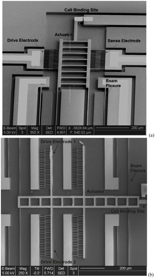
In this paper, we present a novel differential electrode design for electrostatic comb-drive actuators (Figure 1) in ionic media along with circuit models to explain the device behavior. The new actuation scheme mitigates the observed limitations in earlier designs. The new design not only enables actuation of the devices in media suitable for sustaining cells and biological samples but also improves our understanding of the actuators. This advance has led to the development of an actuator system used in biological media for the measurement of cell mechanics.
Figure 1.
Scanning Electron Micrograph of devices indicating drive/sense electrodes, suspension and cell-binding site in (a) Design A (b) Design B
Electrostatics is a commonly used means of actuation in Microelectromechanical Systems (MEMS)[1–3]. Fast actuation, large travel distances and low power consumption are some of the advantages of this technique. Electrostatics is typically used in dielectric media like air or vacuum which can sustain electric fields across the electrodes. The presence of ions in solutions creates problems of shielding and electrochemical reactions. Until recently, this has prevented the use of such devices in aqueous environments. However techniques such as dielectrophoresis and ac-electroosmosis use high frequency voltage signals in ionic liquids. Similarly AC voltage signals can be used at a sufficiently high frequency to enable electrostatic actuation in ionic media [4, 5]. This prevents both the problems of shielding and electrolysis at the electrodes. Since the frequency is typically higher than the natural frequency of the mechanical system, the actuator responds to the Root Mean Square (RMS) value of the actuation signal. This principle is also used to operate parallel plate actuators in liquid media [6, 7] and micro-resonators in aqueous solutions [8, 9]. Electrostatic actuation in aqueous media also finds application in microfluidics as a low power pumping mechanism [10].
The operation of electrostatic devices in aqueous media has been proposed for microfluidic and biological applications[4]. While most the earlier work focused on operation in polar solvents, we presented the experimental characterization of electrostatic actuation in media of varying ionic concentrations[11]. Attenuation observed at high frequencies limited the use of these actuators to media of low ionic strength. Biological cells require solutions of about 0.1–0.15 moles per liter of water (100–150 mM) to be sustained. Actuation in the earlier designs was limited to about 1mM solute concentration.
One of the applications for such an actuator would be to study the mechanical properties of cellular and sub-cellular components [12, 13]. Some of the biophysical techniques developed so far include optical tweezers, atomic force microscopy (AFM), micropipette aspiration and shear flow. Optical tweezers provide high force resolution but are limited to forces that are below the range required for cell biomechanics. AFM techniques are typically used to apply point loads on cell samples and the topography restricts their approach to cells from the top, while cells are known to transduce forces through focal adhesion complexes at the surface [14]. Micropipette aspiration is a technique that has been successfully applied to study the properties of cell membranes and non-adherent cells. MEMS form an important subset of techniques that have been used for manipulation and mechanical stimulation of cells [15]. Sun et al used an external system of electrostatic actuation for manipulation [16]. Similarly, Lin et al measured the forces in cardiac myocyte contraction with microfabricated polysilicon cantilevers [17]. Saif et al [18] and Yang et al [19] employed a functionalized micro-cantilever with an external piezoelectric actuator to measure the mechanical properties of fibroblasts. One of the only examples of on chip actuation was an electro-thermally actuated SU-8 microgripper for cell manipulation developed by Chronis and Lee, however there was no control of the loading profile [20]. Serrell et al developed a MEMS device for uniaxial tensile testing of adherent cells with external piezoelectric actuation [21, 22]. Our actuator is designed towards developing a controllable actuator system for quantifying elastic properties and adhesion forces by directly applying forces to live adherent cells. Immersed actuators would allow integration into microfluidic devices to study the combined effects of mechanical and biochemical stimuli. Further, direct measurement of cellular forces leads to higher resolution, avoiding problems like friction and surface tension which invariably arise in force transmission across membranes and liquid surfaces.
II. Design
The force required for the cell mechanics application is on the order of 1nN–10μN [17, 18]. Since the devices are to be operated in saline media, it is advantageous to maintain operating voltages within 10V since corrosion and electrochemical reactions are significantly lower. The actuation force is proportional to the dielectric constant of the medium and the square of the voltage. This implies that voltages for devices operated in water (relative permittivity 78) are lowered by a factor of √78, compared to those in air or vacuum. The designs include finger spacing of 2 and 5 μm with electrode pair numbers of 25 and 50. The force range of the demonstrated devices is 1.3–6.5 μN at an operating voltage of 5V.
The suspension stiffness is matched closely with expected stiffness of biological samples. While stiffer suspensions would cause higher operating voltages and lower displacement sensitivity, compliant structures would cause handling problems during fabrication and testing. Thus the suspension beams are designed to cover a range of operating stiffness values within these constraints. The width of the flexure is either 3μm or 5μm and the length is between 550–1100 μm, yielding stiffness values in the range 0.02–1.5 N/m. The location of the cell binding site is far away from the comb-drive electrodes such that the effect of the fringing fields is negligible. Moreover the substrate and the moving actuator components are grounded to shield the biological sample from any electric fields.
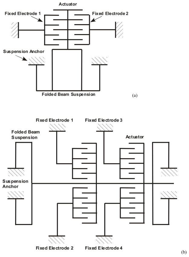
Performances of two different electrode geometries with schematics depicted in Figure 2 are compared. The first design, denoted as Design A, comprises an actuation electrode and shuttle that is grounded by the suspension beam. The second design, indicated as Design B, employs two electrodes connected to the same shuttle that is also grounded by the beam. Design B allows independent voltage signals at each comb electrode. The design variations are discussed in detail in the following sections.
Figure 2.
Schematic of designs A and B. (a) Fixed electrodes 1 and 2 in design A can be used for actuation and sensing. (b) Fixed electrodes 1 and 2 in design B are both used for actuation. Another pair of electrodes 3 and 4 is included to allow for sensing.
III. FABRICATION
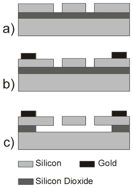
The devices are fabricated on Silicon-On-Insulator (SOI) wafers as shown in Figure 3. The wafers are P-type <100> silicon with resistivity between 0.001–0.02 Ω-cm. The silicon electrodes and suspension beams are etched into the 15 μm device layer by a Deep Reactive Ion Etching (DRIE) process. Metal lines comprising 250 Å chromium as adhesion layer, 500 Å platinum as diffusion barrier and 3000 Å gold electrodes are deposited by e-beam evaporation and patterned by a lift-off process. A wafer saw is used to dice devices before the sacrificial layer release etch. The devices are released by a timed wet-etch of the underlying oxide. The devices are then dried in a liquid CO2 critical point dryer (CPD) to avoid stiction. Figure 1 shows Scanning Electron Micrographs (SEM) of released devices.
Figure 3.
Schematic of fabrication steps. (a) DRIE to pattern silicon comb-drive features (b) Evaporation of metal layers and lift-off (c) Timed wet etch of buried oxide layer followed by release in liquid CO2 CPD.
IV. Theory and Modeling
A comb-drive actuator comprises interdigitated pairs of electrodes, with one suspended by a flexible beam and free to move. For a voltage V applied across the electrodes, the force (F) and displacement (x) relationship is a balance between the suspension stiffness (k) and the electrostatic force [1],
| Eq. 1 |
where k is the suspension stiffness, ε is the permittivity of the medium. N is the number of fingers, d is the gap length and b is the thickness of the device. However, this relation holds only for a dielectric medium in the gaps. The presence of charged species in the media would cause the field distribution to alter significantly. Since ions are mobile, they are also redistributed by the effect of the electric field. Ions of opposite polarity are concentrated at each electrode, resulting in shielding the electric field at the electrode-media interface thus reducing the actuation force. In order to sustain actuation the shielding has to be reduced.
Electrostatic actuation in polar media was first shown by Sounart et al [4]. They demonstrated that the ionic screening of the electrodes can be avoided by using a high frequency signal that modulates the required actuation signal. The frequency is such that the polarity of the electric field changes at a rate faster than that of ionic response and thus avoids electrostatic shielding. Since the electrostatic force is proportional to V2, a static displacement corresponding to the root mean square (RMS) voltage is observed, provided the natural frequency of the suspension is much lower than the signal frequency.
Bazant et al [23] argued that the charging dynamics of an electrode-electrolyte system is governed by the RC time constant of the system. When a solid surface is immersed in an electrolyte, there is spontaneous accumulation of ions near the electrodes due to an interface potential. This layer of ions is comprised of an adsorbed layer at the solid surface called Stern layer and a diffuse layer of ions outside. The characteristic length of the diffuse layer is called the Debye length (λD). Its dependence on the electrolyte properties in terms of the ionic charge valence z, average solute concentration C (atoms/m3), Boltzmann constant kb and temperature T (K) is given by [23]
| Eq. 2 |
For an electrode pair of spacing d immersed in a symmetric electrolyte of charge z, the effective time constant is as
| Eq. 3 |
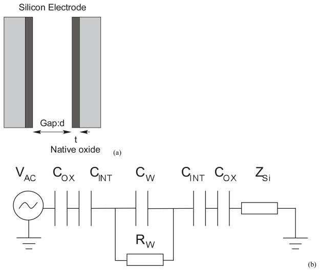
The electrode pair (Figure 4(a)) is silicon with native oxide of thickness t~2 nm [24]. The gap of length d is filled with the electrolyte medium. The circuit model for this is shown in Figure 4(b) where, Cox, CINT and CW are the capacitances of the oxide, double layer interface and the actuator respectively. RW is the resistance of the medium between the electrodes, which is derived from the electrolyte conductivity relation above. The term Zi is not part of the electrode system, but arises due to the resistivity of the substrate through which the signal propagates. Specifically in this case, it is the resistance of the beam suspensions through which the shuttle is grounded. Additionally, the electrodes have parasitic capacitance to ground and other electrodes which are not considered here for the estimation of frequency response. From this circuit, the dominant resistance-capacitance (RC) time constant of this circuit is estimated as
Figure 4.
(a) The electrodes are modeled as capacitors with gap d filled with media and the dielectric native oxide of thickness t. (b) Lumped parameter circuit of the system indicating the electrical double layer capacitance of the interface CINT, native oxide capacitance COX and components of media impedance CW and RW. ZSi is not part of the electrode but arises due to parasitic impedance in the substrate.
| Eq. 4 |
where, εox, εS and εw refer to the relative permittivity of the oxide, stern layer and water respectively. This is identical to Eq. 3 if the interface capacitance were purely formed by the diffuse layer of ions. But in any real system there would be an interface capacitance comprised of the native oxide (in the case of silicon electrodes) and the Stern layer (of thickness λs) in series. Thus the charging dynamics is governed by the effective series capacitance and not by the diffuse layer alone. Hence in practice the series interface capacitance dominates the charging time of the double layer.
V. EXPERIMENTAL DETAILS
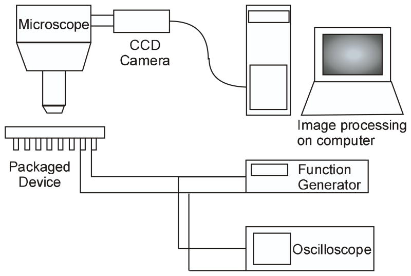
The device was packaged on a ceramic Dual Inline Package (DIP). The actuation voltage was applied between the electrodes, with the substrate grounded. DC voltages were used to actuate the device in air, while AC voltages were used in solutions. The frequencies of AC signals were predicted using the modeling approach described above. The DC signal was supplied through a Kepco power amplifier. The AC signal was applied from an Agilent 33120A or a Tektronix AFG 3102 function generator. The actuator displacement was measured optically by a CCD camera attached to an upright microscope (Figure 5). The displacement was measured by an image processing code written in MATLAB. Pixel resolution of the camera enables a measurement with an accuracy of 20 nm in displacement (for a 50x objective lens).
Figure 5.
Experimental setup with a Leica DMRXA2 upright microscope, and Leica DFC 350fx CCD camera.
The package cavity was filled and rinsed thrice with the test fluid before each measurement. All solutions were made in lab DI water within one hour of acquiring. Ionic solutions of Potassium Chloride (KCl) were made by diluting 1 M standard solution obtained from Fluka. The devices were then stored in DI water to avoid stiction during dry out and collapse of suspended structures. The devices were re-tested by cleaning in acetone and DI water, taking care to keep them wet during all processes.
VI. RESULTS AND DISCUSSION
We present the results for the first Design A and based on the analysis of results, present the revised Design B and comment on the improved performance.
A. Characterization of Design A
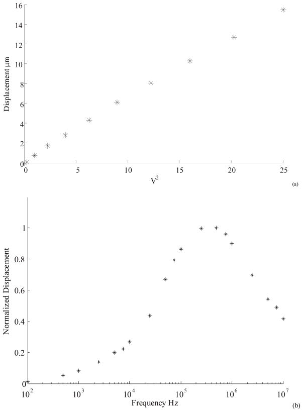
Displacement as a function of frequency and amplitude of applied voltage were evaluated in air, DI water, and ionic media. The devices are characterized by measuring the displacement as a function of voltage and the frequency of the actuating signal in separate experiments. The displacement was found to be linear with the square of voltage at a given frequency (Figure 6(a)). In Figure 6(b), the displacement starts rising around 10 KHz, the characteristic frequency for DI water. However, the displacement response reaches a maximum around 1 MHz and rolls off at higher frequencies due to impedance losses that were larger than anticipated. At these frequencies, the path resistance due to the long suspended beams and the parasitic impedance between electrodes causes the observed roll-off effect. The nature of roll-off indicates the presence of distributed resistor-capacitor (RC) network leading to a “low-pass filter” effect.
Figure 6.
(a) Actuator displacement was found to vary linearly with the square of applied voltage. The actuator was operated in DI water with a square signal at 1MHz frequency. The voltage axis denotes the RMS value. (b) Actuator displacement at constant RMS of 3.5 V plotted as a function of frequency. The plots are normalized to the maximum displacement of 8 μm.
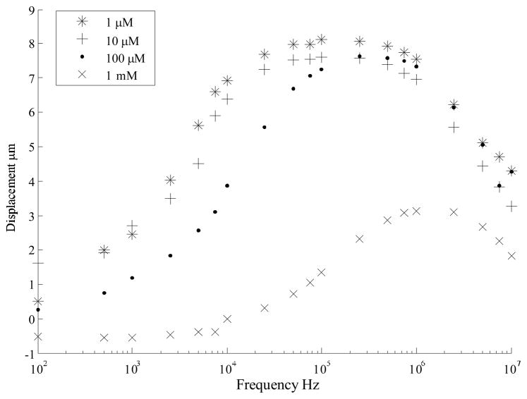
To understand the behavior in ionic solutions, the device displacement was characterized in increasing concentrations of Potassium Chloride (KCl) solution. The results of the tests are plotted in Figure 7. The response shows an increase in transition frequency with media concentration. There is little difference between the curves for 1 μM KCl and 10 μM KCl, which is suspected to be due to the presence of impurities in the solution and at the die surface. The effective conductivity of the medium is increased by these impurities. The effect of dissolved impurities would be lower in the case of higher concentrations of KCl. No measurable displacement was observed for concentrations higher than 10 mM KCl concentration. At these concentrations applying signals below 10 KHz also caused electrolysis accompanied by the release of gas bubbles or corrosion at the electrodes. This was concomitant with the de-lamination of the gold electrodes from the silicon. We believe this resulted from the electrochemical corrosion of the underlying chromium adhesion layer.
Figure 7.
Actuator frequency response is tested in KCl solutions of increasing concentrations. As expected, higher frequency is required to operate at higher ionic strength. However large attenuation is seen at frequency greater than 1 MHz. No displacement was measured for solutions of concentration greater than 1 mM.
B. Characterization of Design B
To address the problems with Design A, we altered the geometry and the method of actuation. Based on the impedance analysis of the device the two-fold problem of parasitic impedance is addressed in Design B. The physics of double layer phenomena dictates the use of high frequency for media of higher concentration, however at higher frequencies, the impedance losses are more significant and this results in severe attenuation.
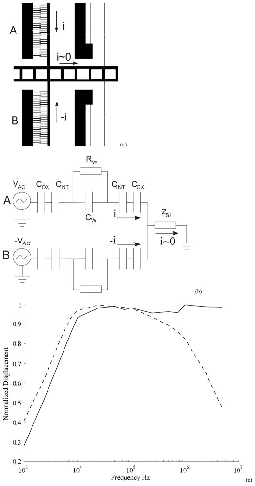
A high conductivity device substrate is chosen to reduce the resistivity of the grounding suspension lines. Due to the parasitic impedance of the structure the reduced resistance alone does not affect the roll-off at higher frequencies. A better solution to the problem is to eliminate or minimize the current flow in the substrate. This is achieved by the differential actuation scheme shown in Figure 8(a) and the schematic in Figure 8(b). The suspended electrode is the common ground that is actuated by two different comb electrodes that carry voltage signals that are out of phase with each other. This ensures that the zero current is injected into the substrate, assuming that the electrode geometries are symmetrically designed. Since the electrostatic force is independent of polarity, the actuator responds to the RMS voltage of the actuation signal for frequencies much higher than the natural frequency of the mechanical suspension. Thus we are able to achieve a non-zero average displacement for a net current of zero in the substrate.
Figure 8.
(a) Electrode geometry layout to achieve the proposed design to minimize substrate current flow by injecting opposing current flows from each electrode (b) Schematic of circuit model indicating the zero current flow through the device and substrate. (c) A comparison of normalized displacement frequency response of a device operated in DI water with signals that are in-phase (dashed) and out-of-phase (continuous) indicates that the displacement in the latter case show reduced attenuation.
The performance of the new design is tested as described before. Figure 8(c) shows the comparison between the old and new actuation schemes on the same device. The data indicated by dashed lines were obtained by driving the electrodes with signals of the same phase, while the data in continuous line were obtained by driving the electrodes with opposing phase. We see that differential electrode actuation eliminates the attenuation at high frequency and that minimizing the current flow through the substrate reduces the attenuation problem.
C. Differential actuation in KCl solutions
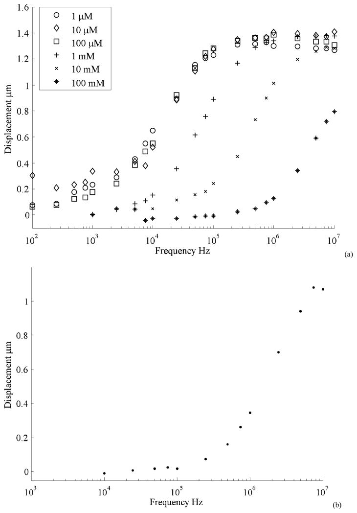
The differential actuation scheme was tested in solutions of increasing ionic strengths made from KCl solutions. The data shown in Figure 9(a) indicate significant improvement in performance for media of higher conductivity. In this case we see that maximum displacement is maintained for KCl solutions of up to 10 mM in concentration. The displacement in 100mM KCl is reduced to about 60% of the maximum value. Since the critical frequency for this solution is calculated to be around 1 MHz it requires an operating frequency above 10 MHz to achieve full displacement, while the driving circuitry is limited to 10 MHz. Distortions in the function generator limits the actuating frequency to 10 MHz. Nevertheless the design changes enable actuation in media of high ionic strengths while in earlier designs the displacements were below measurement resolution even at 10mM concentrations. Unbalanced impedances are also a source of attenuation.
Figure 9.
(a) Performance of the differential actuation scheme for solution of increasing ionic strengths operated at a peak-to-peak signal of 5V. The actuator shows a flat response till 10 MHz. The displacement in 100 mM solution does not reach the maximum at 10 MHz. (b) Displacement of actuator min DMEM solution for differential phase signal. No measurable displacement was observed in the case of actuation by same phase signals in Design B or in Design A.
To test their applicability to biological samples, the devices are characterized in Dulbecco’s Modified Eagle Media (DMEM) with 10% Fetal Bovine Serum (FBS), which is a standard formula for culturing cells lines like fibroblasts. The media has an ionic strength of about 150 mM (isotonic with cells) and a conductivity of about 10 mS/cm. We compared the actuation performance of designs A and B. While no measurable displacement was observed in Design A, the differential signal in Design B indicated about 60% displacement at maximum frequency as shown in Figure 9(b). Full scale displacement should be achieved by employing higher frequency signals. The maximum displacement is currently limited by the driving electronics and future work will expand the frequency and voltage of our signals.
D. Estimation of transition frequency
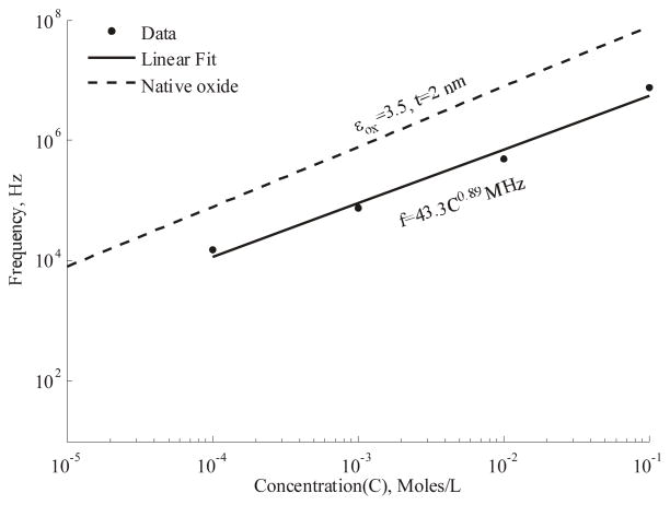
The flat response curves of the differential electrode enable better measurement of the frequency response. We use the data from Figure 9(a) to obtain the transition frequency corresponding to 50% of maximum displacement and these values are plotted against concentration in Figure 10. A linear fit to the data indicates the frequency is proportional to the concentration as expected from Eq. 4.
Figure 10.
(a) A linear fit to the measured transition frequency indicates a trend close to that governed by the native oxide.
Normally the series capacitance is dominated by the lowest value, namely that of the native oxide. The atmosphere equilibrated oxide thickness has been reported to be between 2–4 nm [24]. At these values, the native oxide is the lowest in the series of capacitances at the interface and hence governs the transition frequency. A higher interface capacitance would enable operation at a lower frequency. It is notable that the earlier works had employed either a liquid self-assembled monolayer process [4] or wet chemical oxidation step [5] after device release, thus altering the interface properties. Further analysis and experiments with simplified geometries are required to understand the charging dynamics at the interface in greater detail.
VII. Cell mechanics application
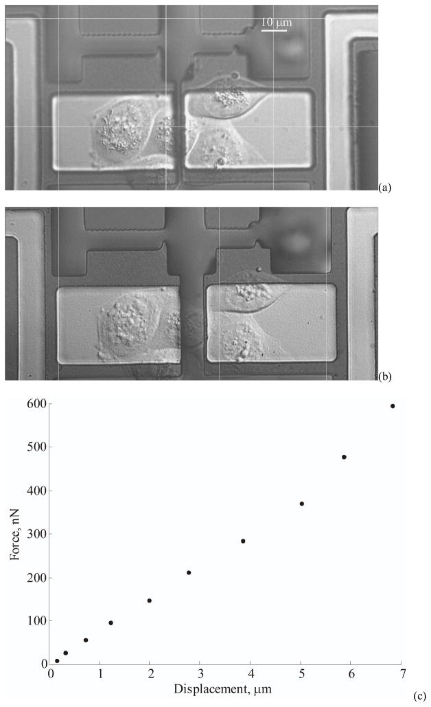
We demonstrate the functioning of the actuator device in an application to measure the mechanical properties of adherent biological cells by stretching the cell sample uniaxially between two suspended binding sites (Figure 12). The binding pad on the right is driven by the actuator and the other acts as the stiff fixed end. The differential actuation mechanism described in Section VI is utilized to operate the system with cells living in culture media. The planar force actuator system enables direct application of forces to the cells through the binding sites. This technique differs from others in that the forces experienced by the cells are directly measured from the device without inferring from deformable substrates.
Figure 12.
(a) Cells spreading and adhering on collagen treated gold pads attached to the actuator. The actuator is shown in its initial unstretched state. (b) Actuator in its final state indicating a stretched cell between the substrates. (c) Measured forces and displacements acting on the cell.
Madine-Darby Canine Kidney (MDCK) cells are grown in a low glucose Dulbecco’s Modified Eagle Media (DMEM) supplemented with 10% Fetal Bovine Serum and 1% Penicillin-Streptomycin solution. A 25 mM HEPES buffer is also added to maintain the pH at 7.4. As seen in Figure 1, the binding cell binding sites are patterned with gold to facilitate cell adhesion. Though the cells preferentially adhere to the hydrophilic gold pads over the silicon surfaces, this alone does not provide sufficient selectivity to block cells. Techniques for cell blocking used in micro-contact printing [25, 26] are not suitable for this application since they do not completely block cells from binding. Moreover the unattached cells and debris in the media affect the electrodes and beam suspension leading to unreliable measurements. Techniques that selectively render the silicon surfaces hydrophobic [27] are also not favorable since the narrow gaps between highly hydrophobic surfaces tend to exclude water and the high surface tension forces causes the combs to stick. Thus we have chosen to place cells on the required regions using a micropipette and micromanipulator. This technique not only allows us to pattern cells in the required regions but also prevents any unattached cells from floating in the media.
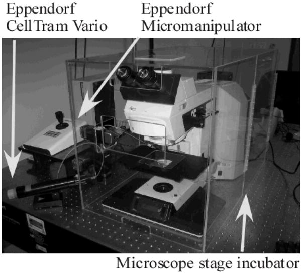
The devices are incubated overnight at room temperature with collagen solution (0.1% in acetic acid) to facilitate cell adhesion. The cells are captured from suspension into a micropipette by generating suction with a piston pump (Eppendorf CellTram-Vario) and released over the pads using an Eppendorf 3-axis piezoelectric micromanipulator and incubated at 37°C for 2–3 hours until they adhere and spread. Since it is important at this step not to disturb the cells until they are adhered, the entire manipulator and microscope setup are placed on a vibration isolation table. A custom built microscope stage incubator (Figure 11) with an AirTherm heater/controller (World Precision Instruments) is used to keep the cells at 37°C. This cell placement technique enables us to successfully grow cells on the selected regions without fouling the electrodes and suspension mechanism with dead cells and debris.
Figure 11.
An image of the cell placement set-up including the custom built acrylic incubator with an AirTherm heater/controller, an Eppendorf micromanipulator and an Eppendorf CellTram Vario piston pump.
The device stiffness is calibrated by electrostatic actuation in air using Eq. 1 to calculate the spring constant ‘k’. For this specific experiment, the calibrated stiffness of the force sensor is 19±3 nN/μm. The displacement of the gold pad is measured using an optical image tracking algorithm. The sensitivity of this measurement yields a resolution of 16.6 nm (pixel/10) in displacement, which corresponds to a force resolution of 322 pN at a frame averaging time of 100 ms under a 63x water immersion objective. Figure 12(a) displays an island of MDCK cells grown on the device with one cell straddling the fixed and suspended substrate. The force is applied by incrementally displacing the actuator while recording the images to measure the displacements. The experiments are conducted at an average strain rate of 100 nm/s to ensure slow quasi-static stiffness measurements. The image in Figure 12(b) shows the cells in the final stretched position. The force-displacement curve of the cells in Figure 12(c) shows an average stiffness of 85±13 nN/μm. The final displacement of the cell is 6.8 μm, starting from an initial gap of 2 μm. The cells show a near linear response at low strains and show considerable stiffening by more than 50% at larger displacements. The stiffness at large strains is about 120±18 nN/μm. The cell did not show any signs of rupturing even at such high strain conditions. The stiffness value shows agreement with earlier reported measurement on adherent hamster fibroblast cells [21], although the cell line is different. However both of these measurements differ significantly from yet another measurement on adherent rat fibroblasts [18]. Apart from using a different cell line, Saif et al [18] also measure passive stiffness at a localized focal adhesion as opposed to entire cell measurement. Further measurements with these devices can be performed to characterize the mechanics of cells and their adhesion mechanisms.
VIII. Conclusion
We have extended the operation range of electrostatic actuators in solutions of high ionic strengths by using a differential actuation design. This design reduces the losses due to impedances which become prominent at high frequency. The transition frequency of actuation varies linearly with the solution concentration. Thus higher frequency is required for higher conducting media. Moreover, the interface capacitance is dominated by the native oxide. A higher interface capacitance by eliminating the native oxide or a metallized electrode can prove beneficial to reduce the operating frequency. We have also implemented an integrated in-plane uniaxial cell stretcher using such an actuator. The system allows us to measure the mechanics of live cells in media by directly applying forces to cells and observing their response. This device can be further developed to mechanically stimulate cells with controlled forces and speeds to study the effects of loading.
Acknowledgments
This work was supported by NSF CAREER Award ECS-0449400. Fabrication work was performed in part at the Stanford Nanofabrication Facility (a member of the National Nanotechnology Infrastructure Network) which is supported by the National Science Foundation under grant ECS-9731293, its lab members, and the industrial members of the Stanford Center for Integrated Systems. V. Mukundan was supported by the Stanford Graduate Fellowship (2003–06).
The authors would like to acknowledge the staff of the Stanford Nanofabrication Facility for the help with the fabrication. We would also grateful for assistance and advice from Prof. James Nelson and Dr. Nicolas Borghi of the Biology Department at Stanford.
Contributor Information
Vikram Mukundan, Mechanical Engineering Department, Stanford University, Stanford, CA 94305 USA.
Beth L. Pruitt, Mechanical Engineering Department, Stanford University, Stanford, CA 94305 USA (phone: 650-723-4559; fax: 650-725-1587; e-mail: pruitt@stanford.edu).
References
- 1.Tang WC, Nguyen TCH, Judy MW, Howe RT. Electrostatic-comb drive of lateral polysilicon resonators. Sensors and Actuators A: Physical. 1990;21:328–331. [Google Scholar]
- 2.Tang WC, Lin MG, Howe RT. Electrostatic Comb Drive Levitation and Control Method. Journal of Microelectromechanical Sytems. 1992;1 [Google Scholar]
- 3.Legtenberg R, Groeneveld AW, Elwenspoek M. Comb-drive actuators for large displacements. Journal of Micromechanics and microengineering. 1996;6:320–329. [Google Scholar]
- 4.Sounart TL, Michalske TA, Zavadil KR. Frequency-Dependent Electrostatic Actuation in Microfluidic MEMS. Journal of Microelectromechanical Sytems. 2005;14:125–133. [Google Scholar]
- 5.Panchawagh HV, Serrell D, Finch DS, Oreskovic T, Mahajan RL. Design and Characterization of a BioMEMS device for invitro mechanical simulation of single adherent cells. presented at ASME International Mechanical Engineering Congress and Expedition; Orlando. 2005. [Google Scholar]
- 6.Rollier AS, Legrand B, Collard D, Buchaillot L. The Stability and pull-in voltage of electrostatic parallel-plate actuators in liquid solutions. Journal of Micromechanics and microengineering. 2006;16:794–801. [Google Scholar]
- 7.Legrand B, Rollier AS, Collard D, Buchaillot L. Suppression of the pull-in instability for parallel-plate electrostatic actuators operated in dielectric liquids. Applied Physics Letters. 2006;88 [Google Scholar]
- 8.Adrega T, Chu V, Conde JP. Electrostatically actuated resonance of amorphous silicon microresonators in water. Applied Physics Letters. 2006;89 [Google Scholar]
- 9.Adrega T, Chu V, Conde JP. Resonance of electrostatically actuated thin-film amorphous silicon microelectromechanical systems microresonators in aqueous solutions: Effect of solution conductivity and viscosity. Journal of Applied Physics. 2007;101 [Google Scholar]
- 10.Bansal T, Chang MP, Maharbiz MM. A class of low voltage, elastomer-metal ‘wet’ actuators for use in high-density microfluidics. Lab on a Chip. 2007;7:164–166. doi: 10.1039/b614419e. [DOI] [PubMed] [Google Scholar]
- 11.Mukundan V, Pruitt BL. Experimental Characterization of Frequency Dependent Electrostatic Actuator for Aqueous Media. presented at Solid State Sensors and Actuators; Hilton Head Island. 2006. [Google Scholar]
- 12.Vliet KJV, Bao G, Suresh S. The biomechanics toolbox: experimental approaches for living cells and biomolecules. Acta Materalia. 2003;51:5881–5905. [Google Scholar]
- 13.Bao G, Suresh S. Cell and molecular mechanics of biological materials. Nature Materials. 2003;2:715–725. doi: 10.1038/nmat1001. [DOI] [PubMed] [Google Scholar]
- 14.Bershadsky AD, Balaban NQ, Geiger B. Adhesion Dependent cell Mechanosensitivity. Annual Review of Cell Development. 2003;19:677–695. doi: 10.1146/annurev.cellbio.19.111301.153011. [DOI] [PubMed] [Google Scholar]
- 15.Sun Y, Nelson B. MEMS for cellular force measurements and molecular detection. International Journal of Information Acquisition. 2003;1:23–32. [Google Scholar]
- 16.Sun Y, Wan KT, Roberts KP, Bischof JC, Nelson BJ. Mechanical property characterization of mouse zona pellucida. Nanobioscience, IEEE Transactions on. 2003;2:279–286. doi: 10.1109/tnb.2003.820273. [DOI] [PubMed] [Google Scholar]
- 17.Lin G, Pister KSJ, Roos KP. Micromachined Polysilicon Heart Cell force Transducer. Journal of Microelectromechanical Sytems. 2000;9:9–17. [Google Scholar]
- 18.Saif MTA, Sager CR, Coyer S. Functionalized BioMicroelectromechanical Systems Sensors for Force Response study at Local Adhesion sites of Single livling cells on substrates. Annals of Biomedical Engineering. 2003;31:950–961. doi: 10.1114/1.1591189. [DOI] [PubMed] [Google Scholar]
- 19.Yang S, Saif T. Reversible and repeatable linear local cell force response under large stretches. Experimental Cell Research. 2004;305:42–50. doi: 10.1016/j.yexcr.2004.12.026. [DOI] [PubMed] [Google Scholar]
- 20.Chronis N, Lee LP. Electrothermally activated SU-8 Microgripper for Single Cell Manipulation in Solution. Journal of Microelectromechanical Sytems. 2005;14:857–863. [Google Scholar]
- 21.Serrell DB, Oreskovic TL, Slifka AJ, Mahajan RL, Finch DS. A uniaxial bioMEMS device for quantitative force-displacement measurements. Biomedical Microdevices. 2007;9:267–275. doi: 10.1007/s10544-006-9032-4. [DOI] [PubMed] [Google Scholar]
- 22.Serrell DB, Law J, Slifka AJ, Mahajan RL, Finch DS. A uniaxial bioMEMS device for imaging single cell response during quantitative force-displacement measurements. Biomedical Microdevices. 2008;10:883–889. doi: 10.1007/s10544-008-9202-7. [DOI] [PubMed] [Google Scholar]
- 23.Bazant MZ, Thornton K, Ajdari A. Diffuse-charge Dynamics in Electrochemical Systems. Physical Review E. 2004;70:021506-1-23. doi: 10.1103/PhysRevE.70.021506. [DOI] [PubMed] [Google Scholar]
- 24.Lukes F. Oxidation of Si and GaAs in air at room temperature. Surface Science. 1972;30:91–100. [Google Scholar]
- 25.Papra A, Gadegaard N, Larsen NB. Characterization of Ultrathin Poly(ethylene glycol) Monolayers on Silicon Substrates. Langmuir. 2001;17:1457–1460. [Google Scholar]
- 26.Tan JL, Liu W, Nelson CM, Raghavan S, Chen CS. Simple Approach to Micropattern Cells on Common Culture Substrates by Tuning Substrate Wettability. Tissue Engineering. 2004;10:865–872. doi: 10.1089/1076327041348365. [DOI] [PubMed] [Google Scholar]
- 27.Maboudian R, Ashurst WR, Carraro C. Self-assembled monolayers as anti-stiction coatings for MEMS: characteristics and recent developments. Sensors and Actuators A: Physical. 2000;82:219–223. [Google Scholar]


