Abstract
Many researchers have proposed the use of biomechanical models for high accuracy soft organ non-rigid image registration, but one main problem in using comprehensive models is the long computation time required to obtain the solution. In this paper we propose to use the Total Lagrangian formulation of the Finite Element method together with Dynamic Relaxation for computing intra-operative organ deformations. We study the best ways of estimating the parameters involved and we propose a termination criteria that can be used in order to obtain fast results with prescribed accuracy. The simulation results prove the accuracy and computational efficiency of the method, even in cases involving large deformations, nonlinear materials and contacts.
Keywords: non-rigid image registration, biomechanical models, dynamic relaxation, eigenvalue estimation
1. Introduction
Many techniques used in neurosurgery have an extremely localized area of therapeutic effect. A surgeon must apply these techniques precisely in relation to current (i.e. intra-operative) patient’s anatomy, directly over specific location of anatomic or functional abnormality. Image-guided intervention systems can help the surgeon in achieving this goal, improving the clinical outcome of surgery [1]. Nakaji and Speltzer list the “accurate localization of the target” as the first principle in modern neurosurgical approaches [2].
As only the pre-operative anatomy of the patient is known precisely from medical images (usually MRI), it is now recognized that the ability to predict soft organ deformation during the operation is the main problem in performing reliable surgery on soft organs.
We are particularly interested in problems arising in image-guided neurosurgery. In this context it is very important to be able to predict the effect of certain procedures on the position of pathologies and critical healthy areas in the brain. The most typical example is the prediction of a displacement field within the brain after opening the skull (so called “brain shift” estimation). A neurosurgeon is interested only in the final, deformed position of the brain. The time-accurate path along which this final state has been reached is of no interest. Therefore, there is a need for an algorithm that would allow a very fast convergence to the deformed state at a cost of loss of accuracy along the path.
Most researchers in the surgical simulation community use mathematical models based on linear elasticity because of their computational efficiency [3–10]. These models are not capable of providing realistic predictions of finite deformations of the tissue because only very small deformations are considered and the material is assumed to have a linear response [11–13]. An efficient finite element algorithm that accounts for both geometric and material nonlinearities is needed.
For close-to-real-time intra-operative applications very high computational efficiencies are required. Highly nonlinear 3D finite element models with about 50000 degrees of freedom need to be solved in less than one minute [14–16].
In the next Section we propose the use of Dynamic Relaxation for finding the deformed state for a finite element problem and examine how the parameters involved can be evaluated. We also present a new way of estimating the accuracy of the results. In Section 3 we present computational examples and Section 4 contains discussion and conclusions.
2. Methods
2.1. Finite element equations
The general equation of motion for a nonlinear system, obtained after the finite element discretisation of the momentum conservation equation, can be written as [17]:
| (1) |
where M is the mass matrix, q is the displacement vector, P is the vector of internal nodal forces and f is the vector of externally applied forces (volumetric forces, surface forces, nodal forces as well as forces derived from contacts). The superimposed dot represents time derivative.
The deformed state solution is obtained when the acceleration is zero, and therefore it is defined by the equation:
| (2) |
In general the relation between nodal forces and displacements in strongly nonlinear because of a combination of different factors: large deformations, material law and contacts.
2.2. Dynamic Relaxation solution algorithm
The basic Dynamic Relaxation (DR) algorithm is presented in [18]. The main ideas are the inclusion of a mass proportional damping in Equation (1) that will increase the convergence speed towards the deformed state and the solving of the obtained damped equation using the central difference method (explicit integration).
After the inclusion of a mass proportional damping, Equation (1) becomes
| (3) |
where c is the damping coefficient.
The following central difference expressions are used for the temporal derivatives
| (4) |
| (5) |
where h is a fixed time increment, n indicates the nth time increment and the superimposed dot represents time derivative. By applying these relations to the damped equation of motion (3), the equation that describes the iterations in terms of displacements becomes:
| (6) |
| (7) |
The iterative method defined by Equation (6) is explicit as long as the mass matrix is diagonal. As the mass matrix does not influence the deformed state solution, given by Equation (2), a lumped mass matrix can be used that maximizes the convergence of the method.
In [18] the convergence of the DR algorithm is studied for linear structural mechanics equations, when the nodal forces can be written as
| (8) |
with K being the stiffness matrix.
We extend this study to the nonlinear case. We propose to use the linearization of the nodal forces obtained by expanding them in a Taylor series and keeping the first 2 terms:
| (9) |
where qk is a point close to qn and Kk is the tangent stiffness matrix evaluated at point qk.
By replacing (9) in (6), we obtain the equation that advances to a new iteration for a nonlinear problem as:
| (10) |
with
| (11) |
It is worth noting that, even if equation (10) has the same form as in the linear case, the point qk is not fixed during the iteration process (as it must be close to qn in order for the Taylor series expansion to be accurate) and therefore the tangent stiffness matrix (and matrix A) changes.
The error after the nth iteration is defined as:
| (12) |
where q* is the solution. Substituting (12) in (10) gives the error equation (valid only close to the solution):
| (13) |
and by assuming that
| (14) |
the following relation is obtained for computing the eigenvalues κ of matrix k:
| (15) |
where A denotes any eigenvalue of matrix A.
The fastest convergence is obtained for the smallest possible spectral radius ρ=|k|. The optimum convergence condition is obtained when:
| (16) |
| (17) |
| (18) |
where A0 and Am are the minimum and maximum eigenvalues of matrix A and therefore ω0 and ωmax are the lowest and highest circular frequencies of the un-damped equation of motion [18].
Because matrix A changes in the nonlinear case, the optimum DR parameters for the beginning of the deformation are usually different from the optimum parameters needed close to the steady state solution. Anyhow, none of these parameters are easy to calculate, as we will show in the following sections. Therefore we propose to estimate the optimum DR parameters corresponding to the steady state solution in the initialization step and then use the estimated values for performing the iterations.
The algorithm we propose for computing the deformed state for a nonlinear problem using DR can be summarized as follows:
-
Initialization:
-
For every iteration step:
Compute the nodal forces corresponding to the current displacements, P(qn) (by assembling the elements’ nodal forces) (see Section 2.6)
Compute next displacement vector using (6)
Check convergence criteria and finish analysis if they are met (see Section 2.7)
Check the maximum eigenvalue of each element and change the mass matrix if needed (see Section 2.4).
The initialization step can be done pre-operatively and therefore we are interested in pre-computing as many parameters as possible in this step. Because the iterative solution is obtained intra-operatively, the computation process must be very efficient.
The computation of the optimum convergence parameters and the other parts of the algorithm are presented in the following sub-sections.
2.3. The effect of eigenvalue estimation on convergence
For the computation of the optimum convergence parameters the maximum and minimum eigenvalues of matrix A must be known. Unfortunately these eigenvalues are not easy to compute and can only be approximated. In this section we present a new study of the way eigenvalue estimation influences the convergence speed. We use the following procedure:
we consider the real range of eigenvalues for matrix A to be known
we make an estimation of the minimum and maximum eigenvalues
the parameters h and c are computed based on the estimated eigenvalues
the modulus of the eigenvalues of k is computed using (15) and represented against the real range of eigenvalues for matrix A
For the figures presented in this section we assumed a small range of eigenvalues (condition number) for matrix A in order to obtain more clear graphs. In reality the range of eigenvalues is orders of magnitude higher.
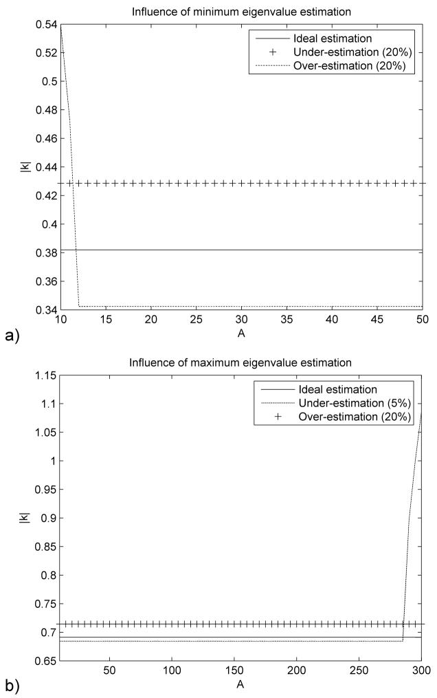
Figure 1(a) shows that under-estimating the minimum eigenvalue A0 leads to an increase of the spectral radius ρ and therefore a decrease in convergence speed. The over-estimation of A0 leads to a decrease of the modulus of all eigenvalues |κ| except for a very narrow range of small eigenvalues. It is important to note that |κ| will never have absolute values higher than 1 because of the minimum eigenvalue estimation and therefore this estimation can not lead to the divergence of (6).
Figure 1.
Influence of the minimum (a) and maximum (b) eigenvalue estimation on the convergence (only one eigenvalue is estimated, the other is assumed to be known). The modulus of the eigenvalues for matrix κ is represented against the real range of eigenvalues for matrix A.
Figure 1(b) shows that over-estimating the maximum eigenvalue Am has the same effect as the under-estimating of A0. It also demonstrates that even a small under-estimation of Am can lead to some of the eigenvalues of matrix k having modulus higher than 1 and therefore to the divergence of (6).
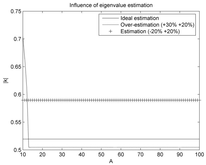
To ensure convergence, it is critical that the maximum eigenvalue Am is overestimated, even if this will lead to a decreased convergence speed. If, at the same time, the minimum eigenvalue A0 is under-estimated, uniform convergence will be obtained for all eigenvalues, with a further decrease in convergence speed. If A0 is over-estimated then it is possible to increase the convergence speed for all eigenvalues except a very narrow range of small eigenvalues (Figure 2).
Figure 2.
Influence of eigenvalue estimations on the convergence (the estimation error for the minimum and maximum eigenvalues is shown in the legend). The modulus of the eigenvalues for matrix κ is represented against the real range of eigenvalues for matrix A.
2.4. Maximum eigenvalue Am. The mass matrix
Using the Rayleigh quotient, it has been demonstrated that the maximum eigenvalue of an assembled finite element mesh is bounded by the maximum eigenvalue of any of the elements in the mesh [17]:
| (19) |
Therefore an estimation of the maximum eigenvalue can be obtained by estimating the maximum eigenvalue of each element in the mesh. Such estimations for different element types are presented in [19].
In the case of a nonlinear problem the maximum eigenvalue changes during the simulation as the geometry of the elements changes and therefore it must be estimated after every iteration step.
Because the mass matrix has no influence on the deformed state (see Equation 2), a fictitious mass matrix that improves the convergence rate can be used. The mass matrix can be chosen such that it reduces the condition number of matrix A, leading to a decrease in the spectral radius ρ (see Equation 16).
In order to reduce the condition number we propose to align the maximum eigenvalue of all elements in the mesh to the same value by changing the density of each element. By doing this we can still use (19) for estimating the maximum eigenvalue and the condition number is at least preserved and generally decreased, as shown in [18].
The process we propose for selecting the maximum eigenvalue and the mass matrix is as follows:
-
At the beginning of the simulation we select a value for the maximum eigenvalue Am and modify the density of each element so that all elements have the same maximum eigenvalue:
(20) where c1 < 1 is a safety factor;
-
During the simulation the maximum eigenvalue of all elements is monitored at each time step. If
(21) then the density of the corresponding element is changed so that relation (20) holds. The factor c2 is chosen so that c1 < c2 < 1.
This process guarantees that the selected maximum eigenvalue Am is an overestimation of the actual maximum eigenvalue during the simulation, therefore ensuring the convergence.
2.5. Estimation of the minimum eigenvalue A0
Estimating the minimum eigenvalue is a difficult problem, especially in the case of nonlinear problems, where an adaptive procedure should be used in order to obtain the optimum convergence parameters. An overview of the procedures proposed by different authors in the context of DR (including an adaptive one) is presented in [18].
The adaptive method proposed in [18] is based on Rayleigh’s quotient and the use of a local diagonal stiffness matrix. The elements of this matrix are computed using finite differences which can be difficult to do for degrees of freedom which have very small displacement variation.
To eliminate these problems we propose to estimate the minimum eigenvalue in the pre-processing stage using an estimation of the actual loading that will be applied intra-operatively. Although the optimum convergence parameters may not be obtained, this reduces the computational effort for each iteration step. By performing more iterations in the same time interval the overall efficiency of the algorithm may be increased.
The minimum eigenvalue computation is done using the procedure presented in [20] by selecting an initial estimation and then calculating a series of approximations of the dominant eigenvalue:
| (22) |
When κDR converges to an almost constant value then the minimum eigenvalue is computed from (15):
| (23) |
This eigenvalue corresponds to the steady state solution obtained using the estimated loading.
2.6. Computation of nodal forces
One of the key ideas in the finite element algorithms development was to use the Total Lagrangian (TL) formulation of the finite element method in which all variables are referred to the original configuration of the system [21]. Second-Piola Kirchoff stress and Green strain are used. The decisive advantage of this formulation is that all derivatives with respect to spatial coordinates are calculated with respect to original configuration and therefore can be pre-computed. The proposed stress and strain measures are appropriate for handling geometric nonlinearities (finite deformations) [17].
The fact that many quantities involved in the computation of nodal forces can be pre-computed leads to a significant decrease in the computational effort. As DR is an explicit method most of the computation time is spent on computing the nodal forces. Therefore it is important to perform these computations as fast as possible.
The basic TL formulation is presented in [21, 22]. We use single-point integration for all the elements in the mesh (improved linear tetrahedrons [23] and under-integrated linear hexahedrons) for computational efficiency. Therefore the nodal forces for each element are computed as:
| (24) |
where according to the notations used in [17], the left superscript represents the current time, the left subscript represents the time of the reference configuration, Pint is the matrix of nodal forces, B0 is the matrix of shape function derivatives, S is the second Piola Kirchoff stress matrix, X is the deformation gradient and V0 is the initial volume. In (24), the matrix of shape function derivatives B0 and the initial volume V0 are constant and therefore can be pre-computed.
The under-integrated linear hexahedron exhibits zero energy deformation modes (hourglass) because of the one point integration. The hourglass modes can be controlled by calculating hourglass forces that oppose the hourglass deformation modes. We have shown in [24] that the hourglass control forces for each element can be computed (in matrix form) as:
| (25) |
where k is a constant that depends on the element geometry and material properties, 0Y is the matrix of hourglass shape vectors and q is the matrix of current displacements. In (25) all quantities except q are constant and can be pre-computed which makes the hourglass control mechanism very efficient.
Because biological tissue behavior can be described in general using hyper-elastic or hyper-visco-elastic models [25] the usage of the TL formulation also leads to a simplification of material law implementation as these material models can be easily described using a relation between the second Piola Kirchoff stress and the deformation gradient [17].
2.7. Termination criteria
One very important aspect of any FEM algorithm is the termination criterion used. If the criterion is too coarse, then the solution might be too inaccurate and if the criterion is too tight, then time is lost in unnecessary computations.
The usual criteria used by FEM software are based on residual forces, displacements or energy. None of these criteria gives any information about the absolute error in the solution and selecting any of these termination criteria is very difficult.
We propose a new termination criterion that gives information about the absolute error in the solution, particularly suited for our solution method. Because DR iterations lead to a strong reduction of the high frequencies, the displacement vector will oscillate around the solution vector with a frequency that converges towards the smallest oscillation frequency. That implies that the error vector e will converge toward the eigenvector corresponding to the lowest eigenvalue. Therefore we can make the following approximation:
| (26) |
By substituting (26) in (13), and considering relations (14) and (15) we obtain:
| (27) |
Therefore after each iteration step the error is reduced by a ratio equal with ρ. We can now obtain an approximation of the absolute error in the solution by applying the infinity norm to relation (27):
| (28) |
| (29) |
This convergence criterion gives an approximation of the absolute error based on the displacement variation norm from the current iteration.
3. Simulation results
The purpose of this section is to assess the accuracy, speed and convergence properties of the proposed algorithms for complex biomechanical models. We are not interested here in validating the models used. Partial validation of the model we use for the brain shift simulation was performed in previous papers with very promising results [16, 26, 27].
Due to its strong resemblance to an explicit procedure the proposed solution method was implemented in C by modifying the Total Lagrangian Explicit Dynamics algorithm we presented in [21]. All simulations were done on a standard 3 GHz Intel® Core™ Duo CPU system using Windows XP operating system.
3.1. Deformation of an ellipsoid
We use this example to demonstrate the accuracy of our method. For an ellipsoid having approximately the size of the brain, we fixed some of the nodes and displaced a few other nodes in order to simulate deformation similar to what happens in the case of a brain shift. The mesh was created using hexahedral elements and has 2200 elements and 2535 nodes. We used an almost incompressible, nonlinear (Neo-Hookean) material model and a large displacement value (2 cm). In our implementation the displacement was applied using a smooth loading curve over 500 iteration steps and a large number of steps (10000) were executed afterwards in order to obtain the deformed state.
3.1.1 Parameter initialization
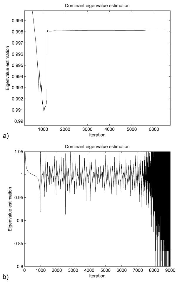
In the initialization stage we chose h = 0.001 (corresponding to Am = 4000000) and made an estimation of the lower eigenvalue A0 = 1000. We then performed a simulation using an estimation of the displacements (which we chose to be half of the real displacements) applied over 1000 iteration steps. The variation of the dominant eigenvalue given by (22) is presented in Figure 3(a). We can therefore estimate the dominant eigenvalue κDR = 0.9982 which leads to the real value of the lower eigenvalue A0 ≈ 110.
Figure 3.
Dominant eigenvalue estimation starting from an over-estimated (a) and an under-estimated (b) initial lower eigenvalue.
In Figure 3(b) we present the dominant eigenvalue estimation obtained if we make an initial estimation of the lower eigenvalue A0 = 10 (under-estimation). We can see that in this case the dominant eigenvalue estimation does not converge to a constant value, as the displacement vector tends to oscillate around the deformed state (because of insufficient damping). In such a case we can increase the initial estimation of A0 and repeat the simulation. This will lead to a faster damping of the high frequencies, as discussed in section 2.3, and a convergence of (22) towards the dominant eigenvalue. Performing multiple simulations in order to find good estimations of the parameters is not a problem, as this step can be entirely done pre-operatively.
3.1.2 Deformed state computation
We performed the displacement computation first by using our algorithm and second by using a well known commercial finite element package – Abaqus [28]. For computational efficiency we use under-integrated hexahedral elements with the hourglass control implemented based on the relations presented in [24]. In Abaqus we used hybrid hexahedral elements, which are the “gold standard” elements for almost incompressible materials. We used the static solver with the default configuration and assumed that the Abaqus simulation provides the accurate results.
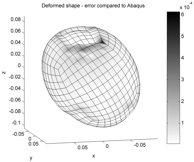
The distribution of the error (absolute difference in nodal position between the two simulations) is presented in Figure 4. The maximum error magnitude of 0.6 mm is obtained at the edge of the displaced area and it is mainly an artifact of using under-integrated elements. Nevertheless the average error is 0.025 mm which demonstrates that our simulation results are more than acceptable. Our algorithm performed 1000 steps in 1.2 seconds, with the resulting accuracy better than 0.1 mm. The Abaqus static solver performed 4 iterations in 8 seconds.
Figure 4.
Absolute difference in nodal positions between our algorithm and Abaqus are colour coded. Dimensions are in meters.
The error estimation based on (29) is presented in Figure 5. As the iteration number increases the estimation is getting closer to the real error value. The estimated error is higher than the real one therefore ensuring the desired accuracy.
Figure 5.
Error estimation (in meters) for the ellipsoid deformation immediately after the loading was applied (a) and after 2000 steps (b).
3.2. Simulation of a brain shift
A more complex simulation is presented here to demonstrate the computational efficiency of the proposed algorithm. A human brain consisting of healthy brain tissue, a tumor and ventricles is enclosed inside the skull. The different parts of the brain are modeled using almost incompressible nonlinear materials (Neo-Hookean) with different properties (for the ventricle the Poisson’s ratio was assumed to be low in order to account for any fluid leakage). The material model is consistent with our previous work on brain material properties [29–31].
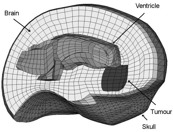
The brain is meshed using mainly hexahedral elements but also includes some improved tetrahedral elements [23]. The mesh has 12182 elements and 13209 nodes (Figure 6). The skull is meshed using 3960 triangular elements. We assume that the initial geometry is known from high quality pre-operative MRI images and we simulate the brain shift by applying displacements on the area of the brain visible during craniotomy, where the displacements can be measured intra-operatively (using a laser range scanner [32] or a stereo vision system [33]). We extracted the required displacements from available intra-operative MRI images. A very similar model has been used in previous papers for brain shift estimation [16, 26, 27].
Figure 6.
The mesh used for the brain shift simulation (only the left half of the brain and skull meshes is shown).
We assume the skull to be rigid and the interaction between the brain and the skull as a frictionless finite sliding contact. Because our algorithm has the property of attenuating the high frequency vibrations in the solution, we can implement this contact as a computationally very efficient kinematic constraint for the brain nodes (any brain node that penetrates the skull surface is brought back on the surface). All external brain nodes except the displaced ones are included in the contact definition. A detailed description of the contact algorithm used is presented in [34].
3.2.1 Parameter initialization
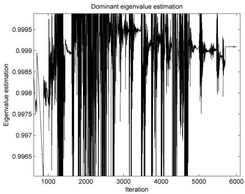
The initialization procedure was performed in the same manner as in the previous experiment. The variation of the dominant eigenvalue is presented in Figure 7. The highly nonlinear behavior of this problem (especially the inclusion of contacts) leads to a lot of oscillations in the graph, but it finally converges towards a constant value. We estimated a dominant eigenvalue of κDR = 0.9991 which leads to the real value of the lower eigenvalue A0 ≈ 56.
Figure 7.
Dominant eigenvalue estimation for the brain shift simulation.
3.2.2 Deformed state computation
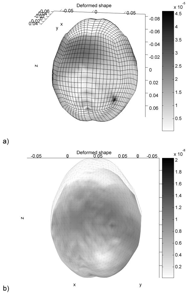
Similar to the ellipsoid deformation simulation the displacements were imposed using a smooth loading curve and the deformed state was obtained by executing a large number of steps (10000). The error in nodal position is presented in Figure 8.
Figure 8.
Absolute nodal position error distribution after 1000 iterations (a) and after 2000 iterations (includes the image of the kull) (b). Dimensions are in meters.
The accuracy of neurosurgery is not better than 1 mm [1]. Voxel size in high quality pre-operative MR images is usually of similar magnitude. Even after 1000 iterations (from which 500 were used for the displacements application) the accuracy of the results is sufficient for image registration, being one order of magnitude higher than the accuracy of any features extracted from the image. By performing 1000 iterations more the accuracy is increased by almost 3 orders of magnitude. The computation time needed for 1000 iterations (on a simple desktop computer) is less than 17 seconds.
In the previous papers where this model has been used the steady state solution was found with the commercial finite element solver LS-DYNA [35]. The displacements obtained were very similar, but each iteration step took more than two times longer in LS-DYNA compared with our algorithms. In the same time, LS-DYNA required more iteration steps to reach the steady state solution, a complete simulation taking about 5 minutes.
The last step of the algorithm (maximum eigenvalue control) can be done in parallel with the rest of the computations by using double buffering of the displacements and mass vectors. This also means that the checking of the maximum eigenvalue will fall one iteration behind the main algorithm, but this can easily be handled by decreasing the value of the safety factor c2 (see section 2.4). This was implemented by using multi-threading and therefore taking advantage of the fact that the processor we used had two cores. The computation time for the brain deformation simulation was reduced to less than 9 seconds for 1000 iterations.
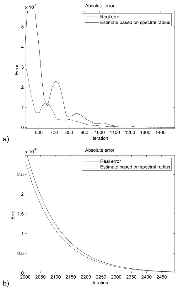
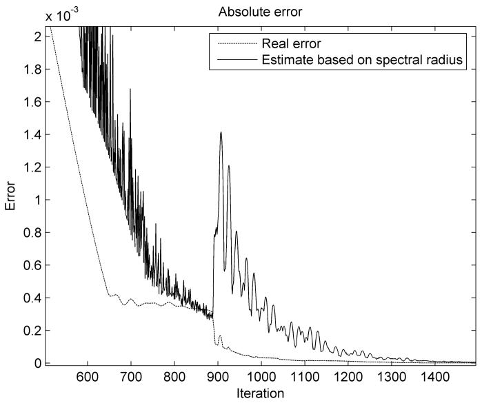
The error estimation is shown in Figure 9. We notice that in the first stages of the simulation the error estimation is not very accurate. This happens because of the strongly nonlinear character of the problem and the assumptions that we made during the derivation of relation (29), mainly the fact that the structure oscillates in the lowest vibration mode. The error estimation becomes more accurate as the number of iterations increases and it converges toward the real error value. It is also higher than the real error and therefore guarantees the imposed accuracy when used as a termination criterion.
Figure 9.
Error estimation (in meters) for the brain shift simulation.
4. Discussion and conclusions
In this paper we propose to use Dynamic Relaxation in the context of the Total Lagrangian formulation for finding the deformed state of a nonlinear finite element problem. The main characteristics of the proposed method are: fast convergence, computational efficiency and the possibility to control the accuracy of the results. These characteristics make it an ideal method for solving image registration problems using bio-mechanical models.
The efficiency of the method derives from the fact that many quantities involved in the computation of the nodal forces are constant and can be pre-computed. We propose that one of the main parameters of the DR algorithm, the lower eigenvalue A0, can be precomputed during the pre-operative stage. We also propose a termination criterion based on the convergence properties of this method which can offer an indication about the absolute accuracy of the results.
We present simulation results that confirm the accuracy and computational efficiency of our solution method. The accuracy is proven by comparing for a given problem the results obtained using our method with the results obtained using the static solver of the commercial finite element code Abaqus and “gold standard” elements that can handle almost incompressible materials. The efficiency of the method is shown by measuring the computation time for a relatively complex simulation of a brain shift where we use different material types and properties for the component parts of the brain (brain tissue, tumour, ventricles), different element types (hexahedrons, tetrahedrons) and contacts between brain and skull. Even for such a complex model (more than 36000 degrees of freedom) the brain shift simulation can be run in tens of seconds on a normal PC. Because of the explicit character of the algorithm, the computation time increases linearly with the number of elements in the mesh.
Although this study is done in the context of the Finite Element Method, most results can also be applied in other cases when the deformed state of a large system of differential equations must be obtained (e.g. mesh-less methods). The computational efficiency of this method will allow researchers to use more comprehensive bio-mechanical models for image registration, leading to an increase in registration accuracy.
Acknowledgments
The first author was an IPRS scholar in Australia during the completion of this research. The financial support of the Australian Research Council (Grant No. DP0343112, DP0664534 and LX0560460) and NIH (Grant No. 1-RO3-CA126466-01A1) is gratefully acknowledged.
Footnotes
Publisher's Disclaimer: This is a PDF file of an unedited manuscript that has been accepted for publication. As a service to our customers we are providing this early version of the manuscript. The manuscript will undergo copyediting, typesetting, and review of the resulting proof before it is published in its final citable form. Please note that during the production process errors may be discovered which could affect the content, and all legal disclaimers that apply to the journal pertain.
Bibliography
- 1.Bucholz R, MacNeil W, McDurmont L. The operating room of the future. Clinical Neurosurgery. 2004;51:228–237. [PubMed] [Google Scholar]
- 2.Nakaji P, Speltzer RF. The Marriage of Technique, Technology, and Judgement. Innovations in Surgical Approach. 2004;51:177–185. [PubMed] [Google Scholar]
- 3.Christensen GE, Johnson HJ. Consistent Image Registration. IEEE Transactions on Medical Imaging. 2001;20(7):568–582. doi: 10.1109/42.932742. [DOI] [PubMed] [Google Scholar]
- 4.Warfield SK, et al. Real-time biomechanical simulation of volumetric brain deformation for image guided neurosurgery. SC 2000: High Performance Networking and Computing Conference; USA: Dallas; 2000. [Google Scholar]
- 5.Clatz O, et al. Patient Specific Biomechanical Model of the Brain: Application to Parkinson’s disease procedure. International Symposium on Surgery Simulation and Soft Tissue Modeling (IS4TM’03); Juan-les-Pins, France: Springer-Verlag; 2003. [Google Scholar]
- 6.Hagemann A, Rohr K, Stiehl HS. Coupling of fluid and elastic models for biomechanical simulations of brain deformations using FEM. Medical Image Analysis. 2002;6(4):375–388. doi: 10.1016/s1361-8415(02)00059-2. [DOI] [PubMed] [Google Scholar]
- 7.Ferrant M, et al. Deformable Modeling for Characterizing Biomedical Shape Changes. Discrete Geometry for Computer Imagery: 9th International Conference; Uppsala, Sweden: Springer-Verlag GmbH; 2000. [Google Scholar]
- 8.Hagemann A, Rohr K, Stiehl HS. Medical Imaging 2000 - Image Processing (MI’00) San Diego, USA: 2000. Biomechanically based simulation of brain deformations for intraoperative image correction: coupling of elastic and fluid models. [Google Scholar]
- 9.Hagemann A, et al. Biomechanical Modeling of the Human Head for Physically Based, Nonrigid Image Registration. IEEE Transactions on Medical Imaging - Special Issue on Model-Based Analysis of Medical Images. 1999;18(10):875–884. doi: 10.1109/42.811267. [DOI] [PubMed] [Google Scholar]
- 10.Hagemann A, et al. Bildverarbeitung fuer die Medizin 1999 (BVM’99) Springer Verlag; 1999. A Biomechanical Model of the Human Head for Elastic Registration of MR-Images. [Google Scholar]
- 11.Carey GF. A Unified Approach to Three Finite Element Theories for Geometric Nonlinearity. Journal of Computer Methods in Applied Mechanics and Engineering. 1974;4(1):69–79. [Google Scholar]
- 12.Martin HC, Carey GF. Introduction to Finite Element Analysis: Theory and Application. New York: McGraw-Hill Book Co; 1973. [Google Scholar]
- 13.Oden JT, Carey GF. Finite Elements: Special Problems in Solid Mechanics. Prentice-Hall; 1983. [Google Scholar]
- 14.Warfield SK, et al. Real-time registration of volumetric brain MRI by biomechanical simulation of deformation during image guided surgery. Computing and Visualization in Science. 2002;5:3–11. [Google Scholar]
- 15.Warfield SK, et al. Capturing intraoperative deformations: research experience at Brigham and Womens’s hospital. Medical Image Analysis. 2005;9(2):145–162. doi: 10.1016/j.media.2004.11.005. [DOI] [PubMed] [Google Scholar]
- 16.Wittek A, et al. Patient-Specific Model of Brain Deformation: Application to Medical Image Registration. Journal of Biomechanics. 2007;40:919–929. doi: 10.1016/j.jbiomech.2006.02.021. [DOI] [PubMed] [Google Scholar]
- 17.Bathe K-J. Finite Element Procedures. New Jersey: Prentice-Hall; 1996. [Google Scholar]
- 18.Underwood P. Dynamic Relaxation. In: Belytschko T, Hughes TJR, editors. Computational Methods for Transient Analysis. New-Holland: Amsterdam; 1983. pp. 245–265. [Google Scholar]
- 19.Hughes TJR. Analysis of transient algorithms with particular reference to stability behavior. In: Belytschko T, Hughes TJR, editors. Computational Methods for Transient Analysis. New-Holland: Amsterdam: 1983. pp. 67–155. [Google Scholar]
- 20.Papadrakakis M. A Method for the Automated Evaluation of the Dynamic Relaxation Parameters. Computer Methods in Applied Mechanics and Engineering. 1981;25:35–48. [Google Scholar]
- 21.Miller K, et al. Total Lagrangian Explicit Dynamics Finite Element Algorithm for Computing Soft Tissue Deformation. Communications in Numerical Methods in Engineering. 2007;23:121–134. [Google Scholar]
- 22.Belytschko T, Liu KW, Moran B. Nonlinear Finite Elements for Continua and Structures. John Wiley & Sons, Ltd.; 2006. [Google Scholar]
- 23.Joldes GR, Wittek A, Miller K. Non-locking Tetrahedral Finite Element for Surgical Simulation. Communications in Numerical Methods in Engineering. 2008 doi: 10.1002/cnm.1185. [DOI] [PMC free article] [PubMed] [Google Scholar]
- 24.Joldes GR, Wittek A, Miller K. An Efficient Hourglass Control Implementation for the Uniform Strain Hexahedron Using the Total Lagrangian Formulation. Communications in Numerical Methods in Engineering. 2007 doi: 10.1002/cnm.1034. [DOI] [Google Scholar]
- 25.Fung YC. Biomechanics Mechanical Properties of Living Tissues. 2. New York: Springer-Verlag; 1993. [Google Scholar]
- 26.Wittek A, et al. Brain shift computation using a fully nonlinear biomechanical model. 8th International Conference on Medical Image Computing and Computer Assisted Surgery MICCAI 2005; Palm Springs, California, USA.. 2005. [DOI] [PubMed] [Google Scholar]
- 27.Wittek A, Hawkins T, Miller K. On the unimportance of constitutive models in computing brain deformation for image-guided surgery. Biomechanics and modeling in mechanobiology. 2009;8(1):77–84. doi: 10.1007/s10237-008-0118-1. [DOI] [PMC free article] [PubMed] [Google Scholar]
- 28.ABAQUS. ABAQUS Theory Manual, Version 5.8. Hibbitt: Karlsson & Sorensen, Inc; 1998. [Google Scholar]
- 29.Miller K, Chinzei K. Constitutive modelling of brain tissue; Experiment and Theory. Journal of Biomechanics. 1997;30(1112):1115–1121. doi: 10.1016/s0021-9290(97)00092-4. [DOI] [PubMed] [Google Scholar]
- 30.Miller K, et al. Mechanical properties of brain tissue in-vivo: experiment and computer simulation. Journal of Biomechanics. 2000;33:1369–1376. doi: 10.1016/s0021-9290(00)00120-2. [DOI] [PubMed] [Google Scholar]
- 31.Miller K, Chinzei K. Mechanical properties of brain tissue in tension. Journal of Biomechanics. 2002;35:483–490. doi: 10.1016/s0021-9290(01)00234-2. [DOI] [PubMed] [Google Scholar]
- 32.Miga MI, et al. Cortical surface registration for image-guided neurosurgery using laser-range scanning. IEEE Transactions on Medical Imaging. 2003;22(8):973–985. doi: 10.1109/TMI.2003.815868. [DOI] [PMC free article] [PubMed] [Google Scholar]
- 33.Sun H, et al. Medical Image Computing and Computer-Assisted Intervention - MICCAI 2003. Springer; Berlin: Heidelberg: 2003. Estimating Cortical Surface Motion Using Stereopsis for Brain Deformation Models; pp. 794–801. [Google Scholar]
- 34.Joldes GR, et al. Realistic And Efficient Brain-Skull Interaction Model For Brain Shift Computation. Computational Biomechanics for Medicine III Workshop, MICCAI; New-York. 2008. [Google Scholar]
- 35.Hallquist JO. LS-DYNA Theory Manual. Livermore, California 94551: Livermore Software Technology Corporation; 2005. [Google Scholar]


