Abstract
A microfabricated flow cytometer was used to demonstrate multiplexed detection of bacteria and toxins using fluorescent coded microspheres. Antibody-coated microspheres bound biothreat targets in a sandwich immunoassay format. The microfluidic cytometer focused the microspheres in three dimensions within the laser interrogation region using passive groove structures to surround the sample stream with sheath fluid. Optical analysis at four different wavelengths identified the coded microspheres and quantified target bound by the presence of phycoerythrin tracer. The multiplexed assays in the microflow cytometer had performance approaching that of a commercial benchtop flow cytometer. The respective limits of detection for bacteria (Escherichia coli, Listeria, and Salmonella) were found to be 103, 105, and 104 cfu/mL for the microflow cytometer and 103, 106, and 105 cfu/mL for the commercial system. Limits of detection for the toxins (cholera toxin, staphylococcal enterotoxin B, and ricin) were 1.6, 0.064, and 1.6 ng/mL for the microflow cytometer and 1.6, 0.064, and 8.0 ng/mL for the commercial system.
Fluorescence-based flow cytometry dates back to the 1960s.1 Essentially, cells or particles are aligned in a flow stream and optically interrogated. Size, density, and fluorescence at multiple wavelengths can be quantified. In many cases, tags such as nucleic acid dyes or fluorescently labeled antibodies are mixed with the samples prior to analysis so that specific targets or cell functions can be identified. Currently, large and complex laboratory-based flow cytometers are used to perform medical diagnostics, such as immunoassays to detect cellular biomarkers, or for environmental monitoring applications, such as classification of marine algae.2 Automated instruments that are smaller and less expensive will be required for point-of-care and on-site analysis.
In the traditional design, the sample containing the particles or cells is pushed through a nozzle into a significantly larger, concentric pipe carrying filtered water. Hydrodynamic focusing aligns the particles into the center of the wider “sheath” stream that tapers to a smaller diameter and focuses particles to pass single-file through the laser beams for analysis. Over the past decade, flow cytometers have become smaller in size and less expensive, but further gains have been limited by the fact that the sheath flow design is not amenable to current microfabrication techniques that can incorporate all elements of the cytometer into a single monolithic chip. A number of researchers have exploited laminar flow, inherently present in microfluidic devices, as a method for focusing particles or cells into a thin stream or layer for interrogation.3–5 Other focusing approaches,6–8 including dielectrophoresis, have been reviewed by Ateya et al.9 Previously studied particle focusing methods suffer from either complicated fabrication procedures or produce data with relatively large variance compared to commercially available laboratory systems.
We have developed a microfluidic sheath flow system that is robust, simple to fabricate, and very compact.10 Chevron-shaped grooves in the channel wall are used to divert sheath fluid from the sides of the channel to the top and bottom, completely surrounding the core stream. The high flow rate of the sheath fluid compared to the sample stream focuses the sample into a very narrow-diameter core that is exposed to the wider laser beams in the interrogation region of the cytometer. Optical fibers deliver light at two wavelengths and collect signals from individual particles at four wavelengths.11
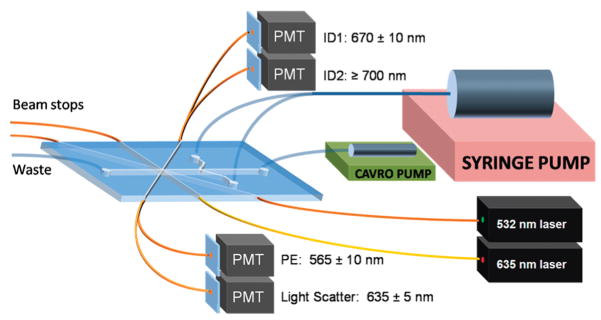
The design (Figure 1) and fabrication of the microflow cytometer and a proof-of-principle demonstration of its ability to distinguish four sets of coded microspheres have been previously described.11 The use of a phycoerthryin tracer associated with antigen–antibody complexes on one microsphere set in the presence of other microsphere sets demonstrated the potential use of a third color for detection and quantification of antigen. In this paper, we use six microsphere sets, each coated with a different antibody, to perform multiplexed immunoassays for bacteria and toxins. We also demonstrate data for microsphere discrimination and immunoassay sensitivity that approach that obtained using a commercial flow cytometer.
Figure 1.
A schematic system layout for the microfabricated flow cytometer for multiplexed detection of bacteria and toxins. A syringe pump was used to provide sheath flow, while a CAVRO pump was used to inject samples into the microfabricated channel. The cables inserted into the PDMS chip guided 635 and 532 nm laser light into the interrogation region and guided excess light out of the beam stops.11 More fiber optics directed emission light to four separate PMTs to collect microsphere ID fluorescences (670 ± 10 nm and ≥700 nm), light scatter (635 ± 5 nm), and phycoerythrin fluorescence (565 ± 10 nm). Sizes are not to scale.
EXPERIMENTAL SECTION
Materials
Polydimethylsiloxane (PDMS, Sylgard 184) was purchased from Dow-Corning (Corning, NY) and used according to manufacturer’s instructions of 10:1 (v/v) base-to-curing agent ratio. Chlorotrimethylsilane was purchased from Sigma-Aldrich (St. Louis, MO). SU-8 photoresist was purchased from Microchem (Newton, MA). Streptavidin-conjugated phycoerythrin was supplied by Prozyme (San Leandro, CA). Carboxy-functionalized polystyrene microsphere sets 98, 81, 77, 56, 50, and 32 (5.6 μm diameter) were purchased from Luminex Corporation (Austin, TX). Llama anti-ricin IgG was purchased from Triple J Farms (Bellingham, WA). Heat-deactivated bacteria Escherichia coli, Salmonella, and Listeria as well as goat anti-E. coli, goat anti-Listeria, and goat anti-Salmonella IgG were obtained from Kirkegaard & Perry Laboratories, Inc. (Gaithersburg, MD). Staphylococcal enterotoxin B (SEB) was purchased from Toxin Technology. Rabbit anti-Staphylococcal enterotoxin B (SEB) was kindly provided by the Naval Medical Research Center (Silver Spring, MD). Cholera toxin was from Calbiochem (San Diego, CA), and rabbit anti-cholera toxin was from Biogenesis (Kinston, NH). Biotinylated goat anti-streptavidin (Bt-G-anti-SA) was purchased from Vector Laboratories (Burlingame, CA).
Device Fabrication
The cytometer channels were microfabricated in PDMS using standard soft lithography procedures. Briefly, a master was created on a silicon wafer by sequential spinning of layers of SU-8 photoresist and exposure with a photomask containing the desired channel geometries and features. Channels were 130 μm high and 390 μm wide. The chevron-shaped grooves extended 65 μm into the top and bottom of the channels. The master was treated with chlorotrimethylsilane vapor to prevent polymer adhesion after development. PDMS was poured onto the master to make layers with a thickness of approximately 1 mm (bottom) or 10 mm (top). The PDMS was removed from the master after curing at 80 °C for 2 h. Fluidic inlets and outlets were cored into the top layer of PDMS, and sections of polyetheretherketone (PEEK) tubing (Upchurch Scientific, Oak Harbor, WA; 400 μm internal diameter) were inserted. The two PDMS pieces (top and bottom) were then bonded together by oxygen plasma treatment. Optical fibers were inserted into the inlets. The device was finally sealed with PDMS cured at 50 °C for 2 h.
Confocal Fluorescence Imaging
The fluid flow in the microfabricated channels was imaged using a Nikon Eclipse TE-2000e inverted confocal microscope with a 10× objective (NA 0.45, WD 4.00 Dry). The image resolution was 512 × 512 pixels with a Z-step size spacing of 5 μm and a pixel dwell time of 7.06 μs. The chip was immobilized on the microscope platform while connected to syringe pumps providing a total sheath flow of 400 μL/min and sample flow of 10 μL/min. Rhodamine dye (0.089 M) was used as the sample fluid. A 40 mW argon laser was used at the 514.5 excitation line, and the spectral detector was set for the 583–593 nm detection range. Images were processed with NIS-Elements AR confocal image processing software (Nikon, Japan).
System Layout
The device has been described in detail elsewhere.11 Briefly, diode lasers at 532 nm (GM32-10H, 10 mW, Intelite, Inc. Minden, NV) and 635 nm (LAS-200-635-15, 15 mW, Lasermax Inc., Rochester, NY) provided excitation light via a single-mode fiber at 90° and a multimode fiber at 45°, respectively. Multimode fibers were positioned opposite the excitation fibers to guide excess light away from the channel and thus minimize scatter off the PDMS. Two multimode fibers equipped with fiber splitters (Fiber Instrument Sales, Inc., Oriskany, NY) collected the light signals from microspheres passing through the interrogation region. Large-angle scatter (45°) from the microspheres was collected at 635 ± 5 nm. Fluorescence was collected using 665 ± 10 nm bandpass (665DF20, Omega Optical, Inc., Brattleboro VT) and ≥700 nm long-pass (LL700, Corion Corp., Franklin MA) filters for microsphere identification and a 565 ± 10 nm bandpass filter for detection of phycoerythrin fluorescence (565WB20, Omega Optical, Inc., Brattleboro, VT). The output of the photo-multiplier tubes (PMTs) was recorded using an analog-to-digital converter (NI USB-6251 M, National Instruments, Austin, TX). Data acquisition and data analysis software was written in LabWindows/CVI (National Instruments, Austin, TX).
Assay Development
Multiplexed assays were performed using microspheres and analyzed using both the microflow cytometer and the commercial Luminex system. Earlier work showed that that multiple microsphere sets could be distinguished in the microflow cytometer using the intensity of two fluorescent dyes at 665 nm and >700 nm, normalized by the 635 nm light scatter signal.11 For this study, antibodies were attached to the carboxy-functionalized microspheres (six Luminex microsphere sets: 50, 56, 71, 77, 81, 98) using the standard two-step carbodi-imide coupling chemistry protocol provided by the manufacturer. After removal of unbound antibody, the microspheres were resuspended in phosphate buffered saline with 0.05% Tween-20 and 1% bovine serum albumin and then stored in the dark at 4 °C until further use.
The microsphere sets were coated with antibodies exhibiting the following specificities: 50-anti-Salmonella, 56-anti-Listeria, 71-anti-cholera toxin, 77-anti-ricin, 81-anti-E. coli, and 98-anti-SEB. The mixture of microsphere sets (~2500 microspheres/well) was incubated with 101–107 cfu/mL bacteria or 0.064–1000 ng/mL toxin at 4 °C. After 30 min, the microspheres were washed on a filter plate and incubated for 30 min at 4 °C with a mixture of biotinylated tracer antibodies (5 μg/mL each) comprised of goat anti-E. coli, goat anti-Salmonella, goat anti-Listeria, rabbit anti-cholera toxin, rabbit anti-SEB, and llama anti-ricin. Streptavidin-phycoerythrin tracer (5 μg/mL) was added for 30 min at 4 °C, and excess tracer was removed by washing the micro-spheres over a filter plate. Aliquots of the microspheres were then analyzed using both flow cytometry systems or exposed to the signal amplification process (described below) and then analyzed.
To achieve signal amplification, biotinylated goat anti-streptavidin antibody (1 μg/mL) was added to the microspheres and allowed to incubate for 30 min. The microspheres were washed using a filter plate, then streptavidin-phycoerythrin (5 μg/mL) was added. After 30 min of incubation, the excess tracer was removed. Note that the incubation times are standard for the laboratory cytometer assays; the purpose of this study was to compare signal levels and device capabilities rather than to minimize assay time. Shorter incubation times are possible.
Data Collection and Processing
The microspheres were analyzed using the microflow cytometer device described and the Luminex flow cytometer. In the microflow system, the micro-spheres were flowed at a concentration of ~5 × 10³ microspheres/mL using a sample flow rate of 10 μL/min and a sheath flow rate of 400 μL/min. A light scatter threshold was set in the data acquisition software to reduce collection of background data. Data from four channels (light scatter at 635 ± 5 nm, identification dye at 670 ± 10 nm, identification dye at ≥700 nm, and phycoerythryin at 565 ± 10 nm) was collected and compiled using the acquisition software. Data processing software correlated the signals detected for each microsphere and created a scatter plot of identification dye at 670 nm vs identification dye at 700 nm. In this scattergram, populations of microspheres could be identified and correlated with the phycoerythrin fluorescence. The mean phycoerythrin fluorescence levels were determined for each microsphere population and compared. These mean fluorescence intensity levels were plotted in a dose–response curve to determine the limits of detection (LODs). Microspheres analyzed in the commercial system were evaluated using mean fluorescence intensity according to the manufacturer’s protocol. Limits of detection were designated as the lowest concentration tested that generated a mean fluorescence signal greater than 3 times the standard error above the mean background of the other five microsphere sets in the same assay.
RESULTS AND DISCUSSION
Particle Focusing
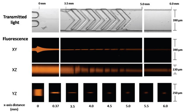
The microflow cytometer uses the process of sheathing, prevalent within flow cytometry, to achieve particle focusing. Rhodamine dye within the microflow cytometer channel was imaged using confocal microscopy to demonstrate the generation of sheath flow using the microfabricated structures (Figure 2). First, the sample fluid was sandwiched vertically between two sheath streams in parallel laminar flow. Chevron-shaped grooves directed fluid from the sides of the channel toward the center in the top and the bottom of the channel, creating three-dimensional sheathing. This design has been described theoretically using COMSOL modeling and experimentally using microscopy.10
Figure 2.
Confocal microscopy images of the sheathing process of the microflow cytometer. The core, with fluorescent dye, is initially sandwiched and focused between two sheath streams (0–3.5 mm) at the sample inlet. Upon entry into the chevron structures (3.5–5.0 mm), the core height is dramatically reduced as the sheath fluid fully surrounds the core. Finally, a tight core stream enters the interrogation region (6.0 mm). The core is introduced at a flow rate of 10 μL/min, and the sheath flow rate is 400 μL/min.
In Figure 2, the transmitted light images show relevant microfabricated structures: the sample inlet, chevron grooves, and the channel directly before the interrogation region. Confocal fluorescence taken in the XY-plane shows the initial sandwiching of the sample stream between the two sheath streams. The XZ-plane shows that the chevron-shaped structures divert the sheath fluids in order to compact the two-dimensionally focused sample stream into a tight, three-dimensionally focused core. Images in the YZ-plane show the focused sample stream with a diameter sufficient to force the microspheres through the center of the interrogation region. The dimensions shown here are consistent with the predicted core dimensions of 24 μm wide by 34 μm high (see COMSOL simulations, Figure S1 in the Supporting Information).
Identification of Coded Microspheres
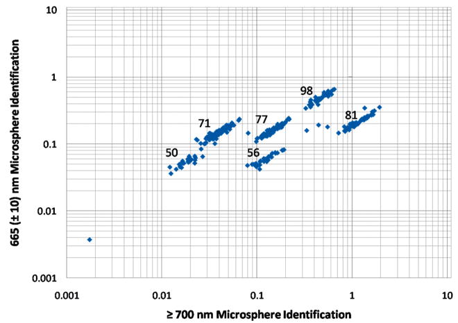
The microspheres are monodisperse (5.6 μm diameter) but have variable amounts of two fluorescent dyes that can be excited with the 635 nm laser and emit within the spectral ranges collected using the 670 nm ± 10 nm bandpass and 700 nm long-pass filters. The amounts of the two fluorescent dyes are used as a code to identify specific microsphere populations. Each coded microsphere population was labeled with antibodies specific for a different target. Figure 3 shows the plot of relative fluorescence intensities of the two emission wavelengths of the mixture of six distinct microsphere populations (50, 56, 71, 77, 81, and 98). While the microflow cytometer does not identify the microsphere sets with the precision of the commercial system, the discrimination capability was sufficient to perform the multiplexing required to achieve a six-plex analysis. Even more microsphere sets can be identified, and the number will continue to increase as all aspects of the system are further optimized.
Figure 3.
A log–log plot of relative fluorescence emission intensities at 670 ± 10 nm and ≥700 nm, normalized to light scatter intensities at 635 ± 5 nm, to identify coded microspheres containing variable amounts of two fluorescent dyes. The emission is a result of excitation by a 635 nm wavelength laser. The numbers associated with each population represent the microsphere code (as designated by the manufacturer).
After collection of the data from microspheres passing through the interrogation region, a data processing program based in LabWindows was used to select specific populations and process four channels of collected optical information: light scatter at 635 ± 5 nm, identification dye at 670 ± 10 nm, identification dye at ≥700 nm, and phycoerythryin at 565 ± 10 nm.
Multiplexed Detection Assays
Antibodies specific for selected bacteria and toxins were conjugated to the coded microspheres to achieve sensitive and selective binding and detection. All six of the microsphere sets were mixed for multiplexed detection of all six bacteria and toxin targets within one assay. The multiplexed measurements also provided sets labeled with antibodies that did not bind the antigen. These sets provided negative controls for nonspecific binding of antigen or tracer antibody to microspheres coated with five other antibodies. For real-world assays, positive controls are commercially available for addition to any assay (e.g., AssayCheX from Radix BioSolutions, Georgetown, TX) and a microsphere set coated with antibodies to an irrelevant target can be used as a negative control.
To compare the performance of the microflow cytometer with the commercial system for multiplexed assays, we incubated a mixture of six microsphere sets each conjugated with specific antibodies with known concentrations of target antigens to establish LODs in our system. Aliquots of the mixed microspheres were exposed to a wide range of concentrations of Salmonella, Listeria, and E. coli (0–107 cfu/mL) as well as cholera toxin, ricin, and SEB (0–1000 ng/mL). The phycoerythrin fluorescence emission level for each microsphere relates to the amount of antigen bound by microsphere. The scales of relative fluorescence units (RFU) are different for the microflow cytometer and commercial system, which is of no significance, but differences in numerical values are relevant when comparing measurements in the same device. In general higher concentrations of antigen resulted in higher RFUs.
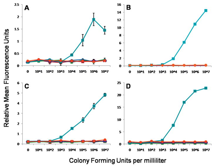
As an example of a dose–response curve obtained using the multiplexed microspheres, Figure 4 shows the detection of E. coli in the microflow cytometer and the commercial cytometer. In both cytometers, the mixture of six microsphere sets were incubated with 0, 101, 102, 103, 104, 105, 106, and 107 cfu/mL of E. coli to determine the dose response. For E. coli detection, microsphere set 81 which had goat anti-E. coli antibody conjugated was used to capture the toxin. After filtering away the unbound sample, the captured bacteria were then evaluated by the addition of a mixture of biotinylated antibodies, including biotinylated goat anti-E. coli. This antigen–antibody complex was then made fluorescent by the addition of streptavidin-phycoerythrin. The phycoerythrin fluorescence of the other microsphere sets, not specific for E. coli, remained at background levels. At high antigen concentrations, even with a wash step, the biotinylated tracer antibody may fail to form a “sandwich” on the target bacteria, lowering the fluorescence signal, in the well-known high-dose hook effect. It may be that at high antigen concentrations, the valency of binding by capture antibodies on the microsphere surface decreases, and the antigen is more easily washed off. In the case of the E. coli assay, the high-dose hook effect can be seen at 107 cfu/mL; this effect was also observed for the Salmonella, cholera toxin, and SEB assays (Supporting Information, Figures S4–S6). The hook effect is frequently reported in Luminex assays. The fact that the microflow cytometer detects the hook effect documents that it provides results comparable to a commercial cytometer.
Figure 4.
E. coli detection assays. Dose response of E. coli colony forming units per milliliter plotted against the relative mean fluorescence units per microsphere measured by (A) microflow cytometer, (B) commercial system, (C) microflow cytometer with signal amplification, and (D) commercial system with signal amplification. Microsphere sets are associated to antigen (◆ = Salmonella, × = Listeria, ▲ cholera toxin, – = ricin, ■ = E. coli, ● = SEB). Standard errors were calculated for all points, but error bars derived from standard errors less than 0.15 RFUs are obscured by the graph markers and do not appear.
Limits of detection were designated as the tested concentration of the antigen that produced a mean signal greater than the average of the mean signals from the five microsphere sets that did not specifically bind the tested antigen (negative controls) plus 3 times the standard error. Previously, Dunbar et al. reported similar data on bacterial pathogen detection in the Luminex system12 with estimated LODs based on extrapolation. The method for calculating the LODs used here is much more conservative. Table 1 shows that, in the standard assay without any signal amplification, the microflow cytometer can detect E. coli, Listeria, and Salmonella at the LODs of 104, 105, and 105 cfu/mL, respectively, compared to 103, 106, and 105 for the commercial cytometer. For toxins, cholera toxin, SEB, and ricin, the microflow cytometer LODs were 3.2, 1.6, and 1.6 ng/mL compared to 1.6, 0.064, and 8.0 ng/mL for the commercial cytometer. The performance of the microflow cytometer was comparable to the commercial system, matching or differing by a single order of magnitude. In some instances, the microflow cytometer outperformed the commercial system (Listeria, cholera toxin, and ricin).
Table 1.
LODs for the Three Bacteria Species and Three Toxins and Their Associated Coefficients of Variation (CV) Were Determined Using the Conventional Benchtop Cytometer (Luminex) and the Microflow Cytometer before and after Signal Amplificationa
| bacteria (cfu/mL) |
toxins (ng/mL) |
|||||
|---|---|---|---|---|---|---|
| cytometer | E. coli | Listeria | Salmonella | cholera | SEB | ricin |
| Luminex (% CV) | 103 (1.0) | 106 (0.7) | 105 (2.7) | 1.6 (1.0) | 0.064 (2.5) | 8.0 (5.6) |
| Luminex (amplified) (% CV) | 103 (3.2) | 106 (0.5) | 105 (1.4) | 1.6 (2.6) | 0.064 (6.6) | 8.0 (2.3) |
| Microflow (% CV) | 104 (11) | 105 (14) | 105 (28) | 0.32 (22) | 1.6 (7.7) | 1.6 (6.7) |
| Microflow (amplified) (% CV) | 103 (21) | 105 (28) | 104 (34) | 1.6 (15) | 0.064 (23) | 1.6 (19) |
Limits of detection were designated as the tested concentration of the antigen that produced a mean signal greater than the average of the mean signals from the five microsphere sets that did not specifically bind the tested antigen (negative controls) plus 3 times the standard error. The coefficients of variation (CVs) were determined for the analyses at the LODs.
Signal Amplification
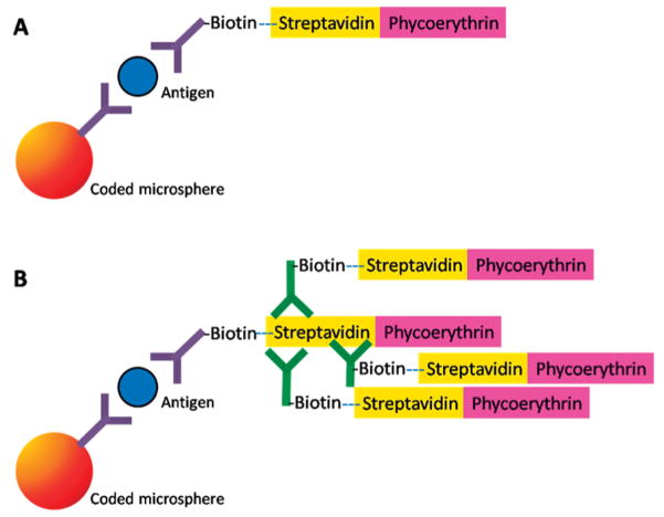
To improve the LODs on the microflow cytometer, a two-step signal amplification method was tested. This method was previously reported for use in commercial benchtop cytometers.13 In this protocol, biotinylated goat anti-streptavidin is added to bind to the first layer of streptavidin-phycoerythrin. This incubation is then followed by the addition of streptavidin-phycoerythrin. This simple amplification protocol13 is reported to provide an increase in fluorescent intensity by a factor of 5–10 (Figure 5). The microspheres with multilayered fluorescent complexes provided the best results when immediately analyzed. Over a few days, signal enhancement was observed to be dramatically reduced; presumably due to dissociation of biotinylated anti-streptavidin antibody from the initial streptavidin-phycoerthrin layer as a result of competition from the second layer of streptavidin-phycoerythrin.13
Figure 5.
Schematic representations of (A) the typical microsphere “sandwich” immunoassays and (B) the signal modification for the immunoassay by the addition of biotinylated anti-streptavidin for additional streptavidin-phycoerythrin labeling.
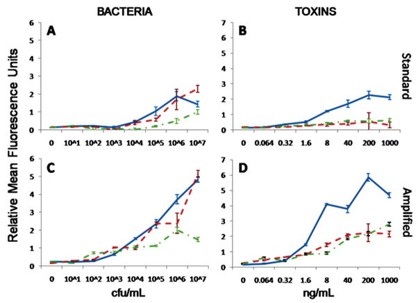
Figure 6 shows the amplified signal compared to the standard microsphere immunoassay in the microfabricated flow cytometer (a similar relative increase in fluorescence signal was found in the commercial system, Figure S8 in the Supporting Information). In all cases, the signal was higher for amplified assays in both the commercial and microfluidic systems. Yet, because background fluorescence also increases, LODs did not automatically improve with the signal enhancement. The microflow cytometer experienced lower background fluorescence increases after signal amplification compared to the commercial system (Figure S9 in the Supporting Information). Thus, the signal-to-background ratio was greater for amplified assays in the microflow cytometer, yielding improved detection limits in three of the six assays. As observed previously, the commercial system’s background fluorescence increased by the same factor as the signal fluorescence, effectively canceling out any advantage of the amplified signal.13 In the original manuscript describing the amplification method, the potential for the amplification method to benefit detection systems with lower sensitivities was foreseen.
Figure 6.
The dose response of the multiplexed microsphere immunoassays in the microflow cytometer for (A) bacteria and (B) toxins (in separate graphs for clarity of presentation) using the standard sandwich immunoassay protocol. The dose response curves for (C) bacteria and (D) toxins with the amplified protocol in the microflow cytometer. Bacteria legend: solid line = E. coli, dotted line = Salmonella, dashed line = Listeria. Toxin legend: solid line = cholera toxin, dotted line = ricin, dashed line = SEB).
Signal amplification did not improve the LODs in the commercial system. Yet in the microflow cytometer, the detection limits improved for E. coli, Salmonella, and SEB. Table 1 shows the LODs in the six assays for both cytometers. In the microflow cytometer E. coli, Listeria, and Salmonella could be detected at 103, 105, and 104 cfu/mL, respectively, compared to 103, 106, and 105 for the cytometer designed specifically to measure the coded microspheres. For the toxins, cholera toxin, SEB, and ricin, in the microflow cytometer, the LODs were 1.6, 0.064, and 1.6 ng/mL, after signal amplification, compared to 1.6, 0.064, and 8.0 ng/mL for the commercial cytometer. While the detection limits for the microflow cytometer were equal to or better than those for the commercial cytometer, the CVs of the signals from the microspheres exposed to these LOD concentrations of target were higher for the microflow cytometer than for the commercial system. The CVs of the LOD values obtained using the microflow cytometer were also generally higher using the amplified protocol than using the standard protocol. The dose–response curves for the five targets, in addition to those in Figure 4, can be found in the Supporting Information (Figures S2–S7).
Assay Variability
At the LODs found in the microflow cytometer, the standard protocol showed a 15% coefficient of variation on average for the six assays tested, while the amplified protocol produced a 23% coefficient of variation on average. Toxin LODs were found to have lower coefficients of variation compared to bacteria in both the standard and amplified protocols. At higher concentrations, the coefficients of variation did not necessarily improve. The coefficients of variation (Table 1) in the commercial system are lower due to the high degree of precision and optimization in the larger, commericial system, but the level of variability is comparable to prototype systems found in the literature.14–18 The greater assay variability in the microflow cytometer is attributed to the 45° illumination of the microspheres by the 532 nm laser to excite the phycoerythrin; the commercial cytometer illuminates at a 90° angle to the sample flow. In support of this point, the range of coefficients of variation for the microsphere fluorescence (both wavelengths), which was illuminated by the 635 nm laser at a 90° angle, was only 3–4%. Future designs will incorporate both lasers at 90° to the sample stream to limit the variability of the system.
CONCLUSIONS
This work presents a flow cytometer which employs an easy-to-fabricate groove-based technology to ensheathe the core stream and minimize the potential for clogging. Optical fibers were integrated into the chip for two-laser excitation and four-wavelength detection, providing the footprint for a very robust system with no requirement for optical alignment by the operator. The microflow cytometer focuses particles in the laser beams delivered by the fibers with a much tighter variance than other hydrodynamically focused microfluidic cytometers reported in the literature.8
Note that the purpose of this research was not to replicate the capabilities of the Luminex flow cytometer nor achieve the ultimate in detection sensitivity. Our purpose was to demonstrate the capability of a microflow cytometer for multiplexed analyses. Multiplexed microsphere immunoassays were conducted simultaneously for six different bacteria and toxins. The LODs were comparable to the commercially available benchtop system specifically optimized for discrimination of the coded microspheres, especially with the use of a simple signal amplification procedure.
Flow cytometers are getting smaller and smaller, with a view toward use at the point of care. However, the devices on the market are very limited in capabilities and targeted primarily to cell counting;19 the capability for multiplexed fluorescence analysis in a small, robust, microfluidic system is critical for development of a more versatile point of care diagnostic device.
Supplementary Material
Acknowledgments
We would like to thank KPL for supplying the antibodies and antigens. J.S.K. is a postdoctoral fellow of the American Society for Engineering Education. The work presented here was performed under NIH Grant UO1 A1075489 and ONR/NRL 6.2 work unit 6336. The views presented here are those of the authors and do not represent the opinion or policy of the National Institutes of Health, Department of Health and Human Services, the U.S. Navy, or the Department of Defense.
Footnotes
SUPPORTING INFORMATION AVAILABLE
Additional information as noted in text. This material is available free of charge via the Internet at http://pubs.acs.org.
References
- 1.Shapiro HM. Cytometry, Part A. 2004;58A(1):13–20. doi: 10.1002/cyto.a.10111. [DOI] [PubMed] [Google Scholar]
- 2.Dubelaar GBJ, Gerritzen PL, Beeker AER, Jonker RR, Tangen K. Cytometry. 1999;37(4):247–254. [PubMed] [Google Scholar]
- 3.Choi S, Park JK. Anal Chem. 2008;80(8):3035–3039. doi: 10.1021/ac8001319. [DOI] [PubMed] [Google Scholar]
- 4.Yang L, Banada PP, Chatni MR, Seop Lim K, Bhunia AK, Ladisch M, Bashir R. Lab Chip. 2006;6(7):896–905. doi: 10.1039/b607061m. [DOI] [PubMed] [Google Scholar]
- 5.Williams MS, Longmuir KJ, Yager P. Lab Chip. 2008;8(7):1121–1129. doi: 10.1039/b802562b. [DOI] [PMC free article] [PubMed] [Google Scholar]
- 6.Goddard GR, Sanders CK, Martin JC, Kaduchak G, Graves SW. Anal Chem. 2007;79(22):8740–8746. doi: 10.1021/ac071402t. [DOI] [PubMed] [Google Scholar]
- 7.Chu H, Doh I, Cho YH. Lab Chip. 2009;9(5):686–691. doi: 10.1039/b812213j. [DOI] [PubMed] [Google Scholar]
- 8.Yang AS, Hsieh WH. Biomed Microdevices. 2007;9(2):113–122. doi: 10.1007/s10544-006-9003-9. [DOI] [PubMed] [Google Scholar]
- 9.Ateya DA, Erickson JS, Howell PB, Jr, Hilliard LR, Golden JP, Ligler FS. Anal Bioanal Chem. 2008;391(5):1485–1498. doi: 10.1007/s00216-007-1827-5. [DOI] [PMC free article] [PubMed] [Google Scholar]
- 10.Howell PB, Jr, Golden JP, Hilliard LR, Erickson JS, Mott DR, Ligler FS. Lab Chip. 2008;8(7):1097–1103. doi: 10.1039/b719381e. [DOI] [PMC free article] [PubMed] [Google Scholar]
- 11.Golden JP, Kim JS, Erickson JS, Hilliard LR, Howell PB, Anderson GP, Nasir M, Ligler FS. Lab Chip. 2009 doi: 10.1039/b822442k. [DOI] [PMC free article] [PubMed] [Google Scholar]
- 12.Dunbar SA, Vander Zee CA, Oliver KG, Karem KL, Jacobson JW. J Microbiol Methods. 2003;53(2):245–252. doi: 10.1016/s0167-7012(03)00028-9. [DOI] [PubMed] [Google Scholar]
- 13.Anderson GP, Taitt CR. Sens Lett. 2008;6(1):213–218. [Google Scholar]
- 14.Gehring AG, Albin DM, Bhunia AK, Reed SA, Tu SI, Uknalis J. Anal Chem. 2006;78(18):6601–6607. doi: 10.1021/ac0608467. [DOI] [PubMed] [Google Scholar]
- 15.Peruski AH, Johnson LH, Peruski LF., Jr J Immunol Methods. 2002;263(1–2):35–41. doi: 10.1016/s0022-1759(02)00030-3. [DOI] [PubMed] [Google Scholar]
- 16.Poli MA, Rivera VR, Hewetson JF, Merrill GA. Toxicon. 1994;32(11):1371–1377. doi: 10.1016/0041-0101(94)90409-x. [DOI] [PubMed] [Google Scholar]
- 17.Wadkins RM, Golden JP, Pritsiolas LM, Ligler FS. Biosens Bioelectron. 1998;13(3–4):407–415. doi: 10.1016/s0956-5663(97)00113-9. [DOI] [PubMed] [Google Scholar]
- 18.Rowe CA, Scruggs SB, Feldstein MJ, Golden JP, Ligler FS. Anal Chem. 1999;71(2):433–439. doi: 10.1021/ac980798t. [DOI] [PubMed] [Google Scholar]
- 19.http://www.invitrogen.com/site/us/en/home/brands/Product-Brand/Countess-Automated-Cell-Counter.html, 2008; www.micronics.net/products/microcyt.php, 2009.
Associated Data
This section collects any data citations, data availability statements, or supplementary materials included in this article.


