Abstract
We have developed a custom scanning laser ophthalmoscope that uses phase plates produced by photolithography to improve the contrast of human retinal images. We combined the scanning engine from a commercial real-time confocal microscope with custom optics to provide medium magnification imaging of the human retina (3° field of view). Defocus and astigmatism were corrected with conventional trial lenses. Higher-order aberrations of the eye were corrected with a phase plate. A 633-nm laser was used for illuminating the retina. Inserting the phase plate into the optical system increased the contrast of a sample retinal vessel by 26%. Additionally, a number of small features of the retina, which were not visible with standard commercial imaging systems, became visible. There results illustrate that, with the rapid development of custom fabrication techniques for refractive corrections, improved diagnostic imaging with little added complexity to existing ophthalmic imaging systems may be realistic.
The introduction of adaptive optics into the ophthalmic research community has resulted in a great deal of interest in both correction of aberrations of the eye for improved vision1–5 and high-resolution imaging of the retina.1,6 One of the major problems in retinal imaging is that contrasts of most features are low because of both multiple scattering from different layers of the retina and the aberrations of the ocular optics.7 The scanning laser ophthalmoscope8 (SLO) has provided a major advantage for retinal imaging because of its ability to improve retinal contrast, especially at longer wavelengths.9 However, both the spatial resolution and the contrast of confocal SLOs are still limited by the degradation in image quality that is imposed by the optics of the eye.
Retinal imaging is commonly used in ophthalmology for the identification and localization of retinal and neural damage. Typically, retinal imaging is performed with fields of view ranging from 10° to 50° of retinal area (approximately 3000–15,000 µ m). Rapidly developing techniques for retinal imaging are bringing higher lateral resolution by use of image processing10,11 and adaptive optics1,6,12 and improved longitudinal resolution by use of low-coherence techniques. 13,14 However, many clinical applications are limited by the low contrast of retinal features. Thus, high magnification is not always the goal for the clinician. Further, identifying the retinal region of interest can be difficult in high-magnification images. A lower-magnification image allows ready identification of the image features in pathology.
We tested whether using customized phase plates allowed higher-contrast imaging of the retina. Although the phase plate used in this study was specially made, the rapid development of excimer laser systems for customized corneal ablation or lathing systems for customized contact lenses may allow manufacturing of custom phase plates at a relatively low incremental cost. To test the approach we developed a new, medium-magnification confocal imaging system (approximately 3° field of view) that uses a combination of trial lenses for correcting a subject’s spherical and cylindrical refractive errors and a custom phase plate15 to correct higher-order aberrations of the eye statically.
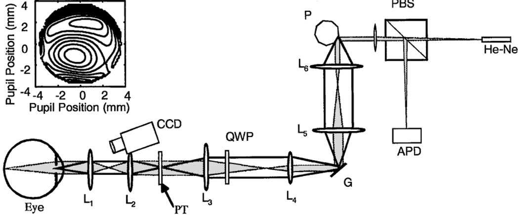
Our custom SLO is based on a design for dermatological applications16 (Fig. 1). This SLO uses a polygon to generate the horizontal scan and a galvanometer to generate the vertical scan.16 We have added a magnification system to increase the pupil size to 5 mm and decrease the field scan to a 3°angle. An optical relay provides a pupil conjugate plane with 1:1 imaging. A polarizing beam splitter and a quarter-wave plate improve our control of reflections and stray light. The wave-front error of the eye was measured as described previously,17 and the phase plate was made with a photolithographic process.15 Measurements of the phase plate show a compensation for 68.5% of the high-order aberrations for the subject. The subject had a total of 1.2-µm rms wave-front error for higher-order aberrations (excluding defocus and astigmatism). The subject’s alignment with the optical axis of the imaging system was maintained by use of a dental impression and by infrared viewing of the pupil. The phase plate was inserted by use of a linear translation stage and was aligned with the pupil by imaging of the exit pupil of the system and alignment of the image of the phase plate with the image of the exit pupil. All light levels were maintained within ANSI standards for safety.
Fig. 1.
Schematic diagram (not to scale) of the imaging system. He–Ne, 633-nm He–Ne laser; PBS, polarizing beam splitter; P, polygon scanner; G, galvanometer scanner; QWP, 1/4 wave plate; PT, phase plate and trial lenses; APD, avalanche photodiode; CCD, pupil position camera for monitoring alignment. Lenses L1 and L2 form the pupil relay, L3 and L4 decrease the scan angle, and L4 and L5 relay the image of the pupil from the polygon to the galvanometer. The inset (top left) shows the wave-front aberration of the subject. The contour intervals are in wavelengths at 540 nm.
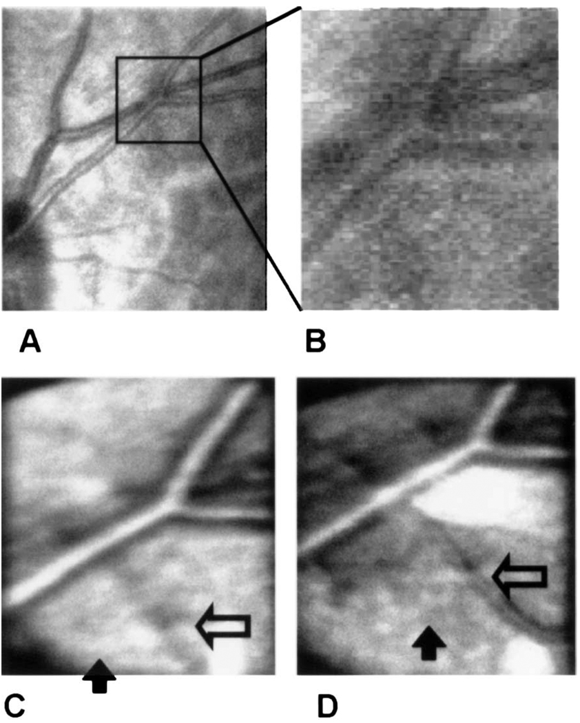
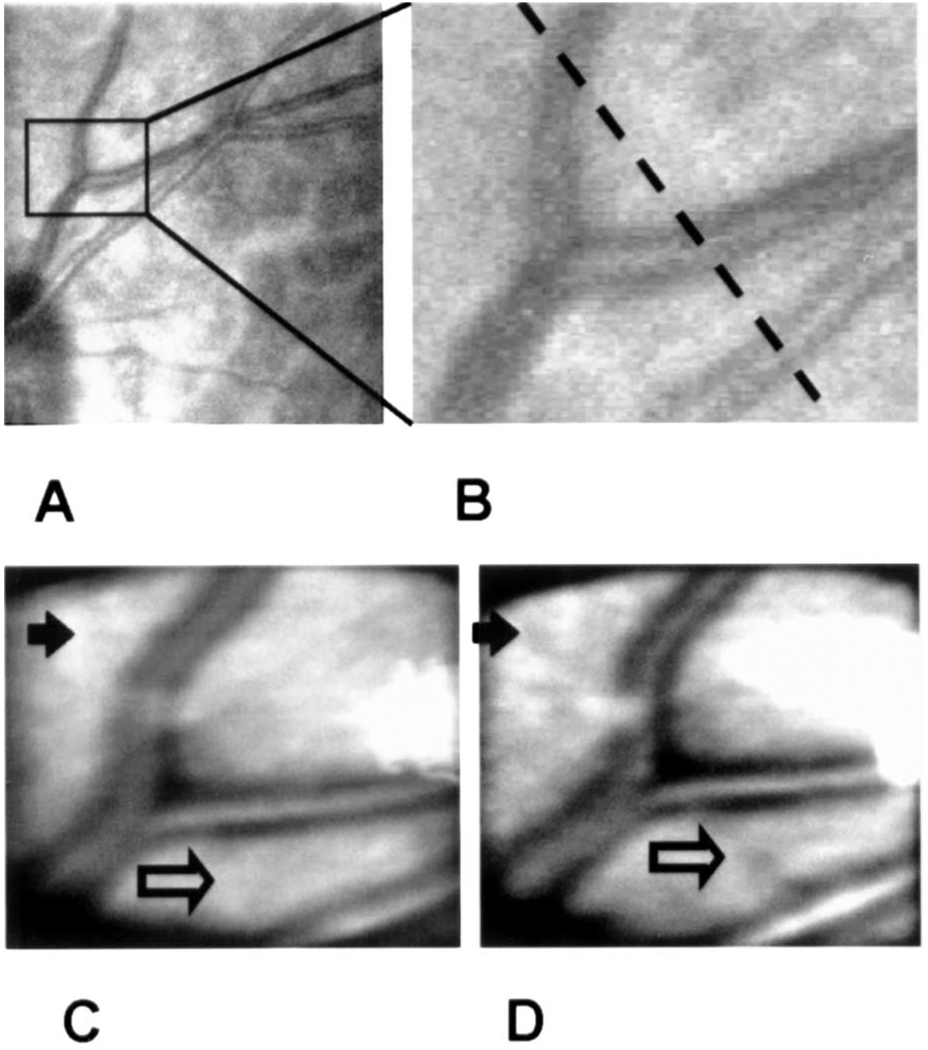
Images obtained with the new imaging system with 633-nm light both with and without the phase plate (Fig. 2C, 2D, Fig 3C, and 3D) are compared with an image of the same region of the retina obtained with a customized Rodenstock SLO18 (Fig. 2A, 2B, Fig 3A, and 3B). Although the new instrument in itself produces better contrast at 633 nm than does the modified Rodenstock device, this improvement can be attributed primarily to the larger pupil (5 mm) size of the new system. This increase improves the confocal sectioning of the retina, decreasing the contribution of multiply scattered light.19 To obtain images we first optimized the image quality, using trial lenses to correct both spherical and cylindrical error (−4.25-D sphere, −1.75-D cylinder), producing the best focus in the plane of the retinal blood vessels. Theoretically there was no effect of the phase plate on the refractive power of the eye, and we confirmed this experimentally by systematically varying the trial lenses. We obtained the image pairs shown in Fig. 2 and Fig 3 by moving the phase plate in and out of the pupil plane, using a lateral translation stage. There were no changes in the image-acquisition system in terms of gain or intensity between image sets. Each image is the average of ten separate images obtained sequentially at an acquisition rate of 10 Hz. Individual images were aligned before averaging.
Fig. 2.
Imaging series comparing imaging modalities. A, Image of the subject’s retina obtained with a research SLO at 633 nm. The box indicates the region of interest for the other images. B, Magnified view of the region from A. C, Image of the same area with the experimental apparatus but without the phase plate. D, Image of the same area after the phase plate is inserted. The open and filled arrows are described in the text. The bright areas are due to reflections from the optics.
Fig. 3.
Image series showing a comparison of imaging modalities. The panels are as identified in Fig. 2. The dashed line in B indicates the cross section along which the intensity was plotted in Fig. 4.
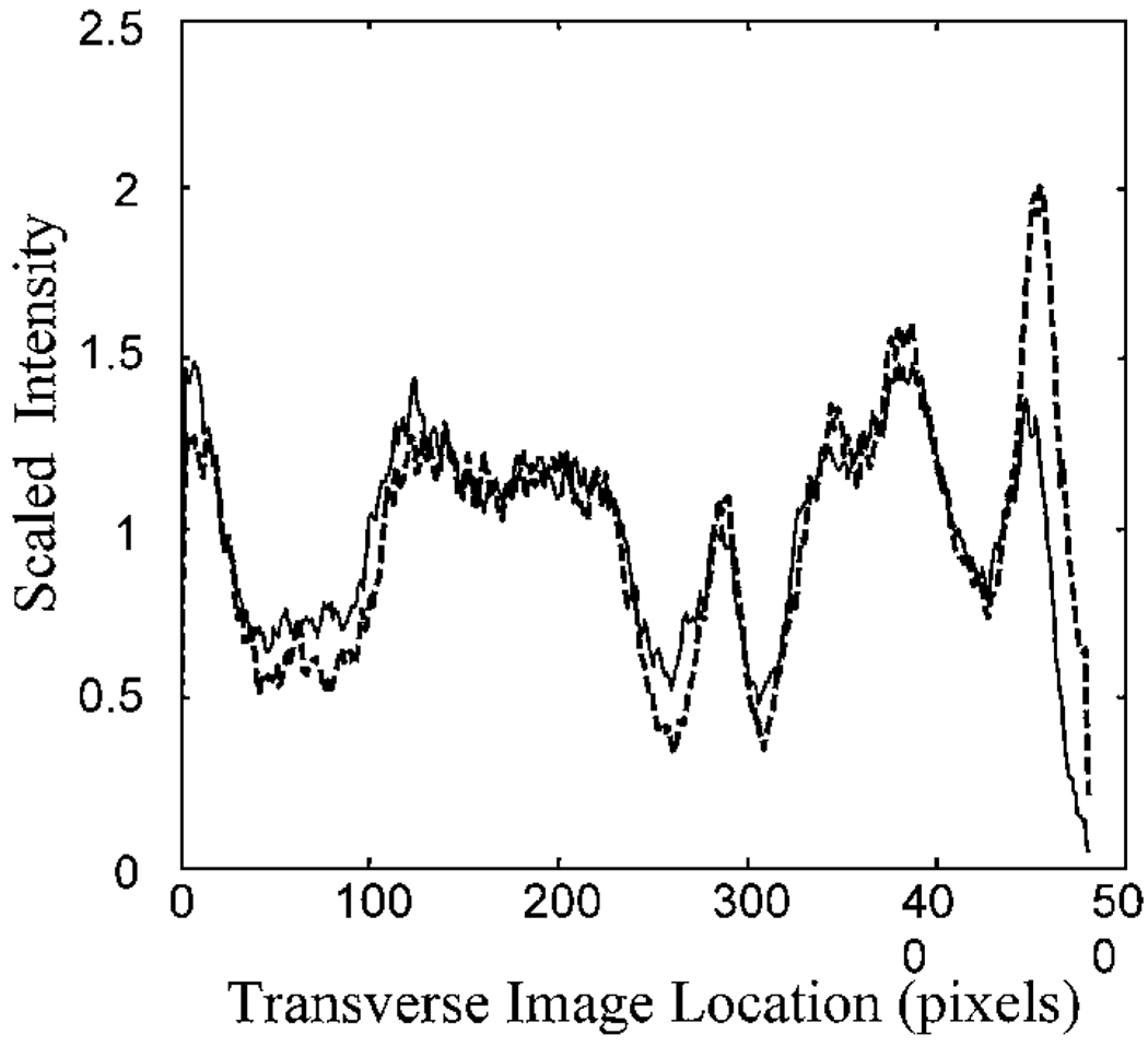
We quantified the change in contrast by measuring the reflectance across the image. In Fig. 4 we plot the relative image intensity along the sample line shown in Fig. 3. For these plots, the intensity of each point in the scan was normalized by the mean intensity. This normalized the data for the slight decrease in illuminance that resulted from absorption by the phase plate (72% transmission, double pass). Calculation of contrast across the large blood vessels indicates that for these vessels the introduction of the phase plate increases Michelson contrast by 26%. The increase of contrast for small vessels is even greater, moving them from undetectable to detectable (open arrows in Fig. 2 and Fig 3). Also resolved are small reflective areas (filled arrows in Fig. 2 and Fig 3). Although we have not identified the anatomical source of these reflective areas, they are fully repeatable and were present in the individual images taken in this region.
Fig. 4.
Intensity along the cross section shown in Fig. 3 for the standard image (solid curve) and the image obtained with the phase plate inserted (dashed curve). The data have been normalized by their mean to correct for the slightly decreased intensity with the phase plate inserted.
Although optimal image improvement5 may occur with the inclusion of closed-loop adaptive optics20,21 and image stabilization22 within the imaging system, these processes are currently expensive and technologically demanding. However, considerable effort is being devoted to the development of sculpting techniques capable of shaping both the cornea and contact lenses. These approaches may be applicable to the rapid production of phase plates that can be customized. If it becomes possible to fabricate custom phase plates rapidly, our data indicate that they will provide a substantial improvement in retinal imaging while adding little complexity to imaging systems.
In conclusion, this work shows that significant improvements in retinal image quality can be achieved by coupling of a fixed phase-correcting system to an appropriately designed confocal scanning laser ophthalmoscope. With the rapid developments in improved corrections of the aberrations of the eye, there is promise for improved diagnosis and detection of retinal damage as well as for a more widely available approach to improved retinal imaging for research.
Acknowledgments
This research was supported by a Convenio de Co-operación Científica y Tecnológica Spain–USA grant from the Ministerio de Asuntos Exteriores, Spain, by grant EYO7624 from the National Eye Institute, and by the Comisión Interministerial de Ciencia y Tecnología, Spain (grant TIC98-0925-C02-02). The authors thank Robert Webb for discussions during construction of the imaging system and Lucid Systems (Rochester, New York) for aid with the confocal imaging platform. S. Burn’s e-mail address is sburns@vision.eri.harvard.edu
Footnotes
OCIS codes: 120.3890, 170.4460, 180.1790, 330.4300, 330.4460.
Contributor Information
Stephen A. Burns, Schepens Eye Research Institute, 20 Staniford Street, Boston, Massachusetts 02114
Susana Marcos, Instituto de Optica “Daza de Valdés,” Consejo Superior de Investigaciones Científicas, Serrano 121, Madrid 28006, Spain.
Ann E. Elsner, Schepens Eye Research Institute, 20 Staniford Street, Boston, Massachusetts 02114
Salvador Bara, Area de Optica, Facultade de Fisica, Universidade de Santiago de Compostela, 15706, Santiago de Compostela, Galicia, Spain.
References
- 1.Liang J, Williams DR, Miller DT. J. Opt. Soc. Am. A. 1997;14:2884. doi: 10.1364/josaa.14.002884. [DOI] [PubMed] [Google Scholar]
- 2.Applegate RA, Howland HC. J. Refractive Surg. 1997;13:295. doi: 10.3928/1081-597X-19970501-16. [DOI] [PubMed] [Google Scholar]
- 3.Vargas-Martin F, Prieto PM, Artal P. J. Opt. Soc. Am. A. 1998;15:2552. doi: 10.1364/josaa.15.002552. [DOI] [PubMed] [Google Scholar]
- 4.Zhu LJ, Bartsch DU, Freeman WR, Sun PC, Fainman Y. Optom. Vis. Sci. 1998;75:827. doi: 10.1097/00006324-199811000-00025. [DOI] [PubMed] [Google Scholar]
- 5.Yoon G, Cox I, Williams DR. Invest. Ophthalmol. Visual Sci. 1999;40:211. [Google Scholar]
- 6.Roorda A, Williams DR. Nature. 1999;397:520. doi: 10.1038/17383. [DOI] [PubMed] [Google Scholar]
- 7.Howland HC. J. Refractive Surg. 2000;16:S552. doi: 10.3928/1081-597X-20000901-11. [DOI] [PubMed] [Google Scholar]
- 8.Webb RH, Hughes GW, Delori FC. Appl. Opt. 1987;26:1492. doi: 10.1364/AO.26.001492. [DOI] [PubMed] [Google Scholar]
- 9.Elsner AE, Burns SA, Weiter JJ, Delori FC. Vision Res. 1996;36:191. doi: 10.1016/0042-6989(95)00100-e. [DOI] [PubMed] [Google Scholar]
- 10.Iglesias I, Artal P. Opt. Lett. 2000;25:1804. doi: 10.1364/ol.25.001804. [DOI] [PubMed] [Google Scholar]
- 11.O’Connor NJ, Bartsch DU, Freeman WJ, Mueller AJ, Holmes TJ. Appl. Opt. 1998;37:2021. doi: 10.1364/ao.37.002021. [DOI] [PubMed] [Google Scholar]
- 12.Dreher AW, Bille JF, Weinreb RN. Appl. Opt. 1989;28:804. doi: 10.1364/AO.28.000804. [DOI] [PubMed] [Google Scholar]
- 13.Fercher AF, Hitzenberger CK. J. Mod. Opt. 1991;38:616. [Google Scholar]
- 14.Huang D, Swanson EA, Lin CP, Schuman JS, Stinson WG, Chang W, Hee MR, Flotte T, Gregory K, Puliafito CA, Fujimoto JG. Science. 1991;254:1178. doi: 10.1126/science.1957169. [DOI] [PMC free article] [PubMed] [Google Scholar]
- 15.Navarro R, Moreno-Barriuso E, Bara S, Mancebo T. Opt. Lett. 2000;25:236. doi: 10.1364/ol.25.000236. [DOI] [PubMed] [Google Scholar]
- 16.Rajadhyaksha M, Anderson RR, Webb RH. Appl. Opt. 1999;38:2105. doi: 10.1364/ao.38.002105. [DOI] [PubMed] [Google Scholar]
- 17.Navarro R, Losada MA. Optom. Vis. Sci. 1997;74:540. doi: 10.1097/00006324-199707000-00023. [DOI] [PubMed] [Google Scholar]
- 18.Elsner AE, Burns SA, Hughes GW, Webb RH. Appl. Opt. 1992;31:3697. doi: 10.1364/AO.31.003697. [DOI] [PubMed] [Google Scholar]
- 19.Elsner AE, Miura M, Burns SA, Beausencourt E, Kunze C, Kelley LM, Walker JP, Wing GL, Raskauskas PA, Fletcher DC, Zhou Q, Dreher AW. Opt. Express. 2000;7:95. doi: 10.1364/oe.7.000095. www.opticsexpress.org. [DOI] [PubMed]
- 20.Hofer H, Artal P, Singer B, Aragon JL, Williams DR. J. Opt. Soc. Am. 2001;18:497. doi: 10.1364/josaa.18.000497. [DOI] [PubMed] [Google Scholar]
- 21.Fernandez EJ, Iglesias I, Antequera N, Artal P. Invest. Ophthalmol. Visual Sci. 2001;42:544. [Google Scholar]
- 22.Ferguson RD, Magill JC, Frish MB, Elsner AE, Webb RH. Invest. Ophthalmol. Visual Sci. 2001;42:4255. [Google Scholar]


