Abstract
We describe a high throughput patterning process used to create arrays of molecular-scale features for the study of cytoskeletal protein binding interactions. The process uses a shadow-evaporated metal mask to facilitate lift-off of features defined by nanoimprint lithography. This simple and robust approach alleviates difficulties in pattern transfer of ultra-small features and results in arrays of highly ordered sub-10 nm features which are then functionalized with extracellular matrix proteins. Application of these arrays is demonstrated in cell spreading assays.
I. Introduction
The spatial arrangement of transembrane receptors in the extracellular matrix (ECM) is believed to play a significant role in intracellular as well as in cell-cell and cell-ECM signaling events.1–4 Understanding how this type of spatial order affects cell behavior will yield enormous insight into the fundamental workings of these systems and may enable greater control over cellular function in drug design and tissue engineering.
An engineered system that mimics the extracellular environment with a well-defined geometry of protein-protein interaction domains can be an excellent platform for in-vitro study of these interactions. However, controlling this geometry on single-molecule level is extremely challenging, as it requires precise patterning of surfaces at the size scale of biomolecules.
The overall goal of this work is to study the role of spatial ordering of integrin cytoplasmic tails for the binding of other proteins, such as talin (a 56 nm polyvalent protein complex), which are involved in the building of focal adhesion (FA) complexes, by which the actin cytoskeleton attaches to the ECM. It was previously demonstrated that nanoscale clustering of RGD (arginine-glycine-aspatate) motifs of the ECM, which are recognized by αvβ3 integrins with a high affinity, is important in the initial stages ofcellular interactions with the ECM.5,6 It was also shown that proper slip bonds of RGD motifs with the cytoskeleton through talin cannot be formed with single RGDs under dilute conditions, but can be formed using trimers of RGD with the maximal distance of 60 nm between RGDs within the trimer.7 In general, it is believed that for focal adhesion activation more than one integrin molecule should be clustered together, with a spacing that matches the dimensions of talin.8
In this work we develop a system that mimics biological spatial order by using nanofabricated structures to provide multiple protein binding sites with nanometer-scale separations. The nanostructures are organized into arrays of individual molecular binding sites with precise control over size and distance. The nanoscale patterns can be used for both molecular-scale studies as well as cellular-scale assays of the dependence of binding of large cytoskeletal proteins on the spatial arrangement of ligands.
A study of cell spreading on substrates patterned with sub–10 nm Au nano-dots functionalized with RGD motifs through thiol bonding was reported by Arnold et al.9 The patterning was done using diblock-copolymer micellar lithography, which forms a hexagonal arrangement of dots, with the spacing between the dots controlled by the molecular weight of one of the diblock copolymer constituents.10 They found that cell spreading and attachment was markedly reduced for dot spacings greater than ~ 73 nm, and they concluded that this spacing range is a universal scale for integrin clustering and activation. In their approach, they were able to control either the spacing between the dots or the overall dot density. In contrast, our work, as described below, uses lithographically-formed patterns consisting of arrays of metal nanodots arranged in pairs. Each array maintains a constant density of pairs, while the spacing between the dots in the pairs is varied from one array to another. In this way, we can focus on the importance of the geometric arrangement of ligands independent of the total number of ligands presented for binding (i.e., density).
Figure 1 shows the basic scheme used in this study. The dots, ~ 5–10 nm in diameter, can be functionalized with linker molecules (RGD sequences in our case) that specifically interact with individual transmembrane binding proteins such as integrins. The small dimension of the dots should ensure that only one integrin molecule, which is about 8–12 nm in width,11,12 will bind to a single functionalized dot. The dots are patterned on a glass surface, which is otherwise covered with a passivation layer (typically a monolayer of polyethyleneglycol (PEG)) that prevents non-specific interactions of the proteins with the glass surface. The PEG layer must be thinner than the height of the dots (i.e. less than ~ 5 nm). The intra-pair spacing (distance between two dots in a pair) is varied over a range that spans the distance between binding domains of the talin molecule (~ 40–100 nm). The spacing between the centers of two neighboring pairs is designed to be large enough to isolate the pairs from one another.
Figure 1.

Schematic of the nanoarray chip. The chip contains an array of lattices with varying parameter b, which defines the distance between protein binding sites, and a constant distance between neighboring pairs (c) of 200nm. Each lattice has the same total number of binding sites.
We previously demonstrated the fabrication of nanoscale bioarrays using electron beam lithography.13 However, e-beam patterning suffers from low throughput, making it somewhat impractical for biology experiments that require a large number of samples with relatively large area coverage. Nanoimprint lithography (NIL) provides a fast, low cost method for the replication of ultra-small features with high throughput.14 Although the size of the imprinted features is, in principle, nearly unlimited,15 it is still somewhat challenging to achieve reliable pattern transfer by lift-off for sub-10 nm features. This is a consequence of the aspect ratio of the features on the NIL template, which in turn requires a thin imprint resist to image these features. Typically, bilayer resists have been used to overcome this problem,16,17 however these have not been shown to work reliably for feature sizes in the 10 nm range and below. In this work we demonstrate a simple and robust method for high-throughput fabrication of arrays of sub-10 nm features using NIL using a pattern transfer technique based on a sacrificial hard mask. We also demonstrate biofunctionalization of these arrays for their application to the study of cytoskeletal protein binding interactions.
II. Nanofabrication of Bioarrays
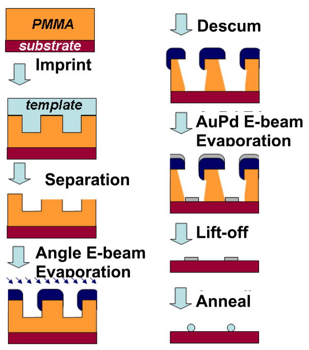
The process used to form nanoscale bioarrays is shown schematically in Fig. 2. NIL templates consisted of diamond-like carbon (DLC) films grown by PECVD on silicon wafers. The templates were patterned by e-beam lithography using a scanning electron microscope (FEI XL 30 Sirion) equipped with a Nabity NPGS pattern generator. Arrays of dots with the diameter of ~ 15–20 nm were written in hydrogen silsesquioxane (HSQ, Fox-12™, Dow Corning)18 The resist images were transferred into the DLC by reactive ion etching in O2 to a depth of 30–50 nm, followed by the removal of the HSQ mask by a short dip in dilute HF. The DLC templates were exposed to a C4F8 plasma in order to achieve a low energy surface, which is essential for the successful separation of the template from the imprinted substrate.19
Figure 2.
Schematic process flow of array fabrication.
Thermal NIL was done in a Nanonex BX-200 system using the DLC templates and either silicon wafer or glass coverslip substrates. The NIL resist was polymethyl-methacrylate (PMMA, Mw = 35 K), and the imprint was done at an optimized temperature of 180 °C at a pressure of 500 psi for 5 minutes. The initial thickness of PMMA films was ~ 60 nm. Fig. 3 shows a typical image of PMMA following imprint of the dot pair pattern.
Figure 3.
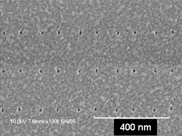
PMMA, imprinted with the template that defines arrays of pairs of 15–20nm diameter dots.
In a conventional lift-off process, a negative resist slope (i.e., an undercut) is frequently desirable. This can be challenging in high resolution NIL, where features only a few tens of nm (or less) in size are imprinted; only positively sloped or vertical side walls can be achieved in resist by NIL, and the resist thickness is limited by the aspect ratio of template features. For features with dimensions of ~ 20 nm or less, the resist thickness should not exceed ~ 60–80 nm. In order to obtain a robust lift-off, a process using a shadow-evaporated hard mask was developed for our application. A metal layer (15 nm of titanium was used in this case) was deposited by e-beam evaporation, with the sample held at a tilt of 45° relative to the metal vapor flux. For an aspect ratio greater than 1, a metal hard mask is deposited on the top of the substrate, covering the PMMA surface and the top part of the sidewall in the imprinted opening in the resist, which is exposed to the flux. The hard mask deposition was followed by an oxygen plasma descum to remove the residual resist typically left after imprint. The descum in this case also creates an undercut beneath the hard mask due to its partially isotropic nature. This forms a robust stencil for the definition of the final pattern. 3 nm AuPd (60%/40%) was deposited by e-beam evaporation with an adhesion layer of Ti (1 nm). Liftoff was done by immersion in boiling acetone. A cross section of the nanoimprinted pattern after the Ti hard mask deposition, descum and AuPd evaporation (before liftoff) is shown in Fig. 4, where partially etched PMMA and the Ti hard mask are clearly seen, as well as the deposited AuPd features.
Figure 4.
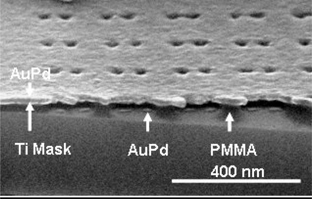
Cross section SEM image of nano-patterned array before lift-off.
An angle evaporated hard mask provides several benefits to the fabrication process of metal dots array by thermal NIL: a) it allows the use of templates with a relatively low aspect ratio features (more than 1:1 is sufficient with a tilt angle of 45°); b) it significantly “widens” the process window for the descum process, making the system very tolerant to many possible changes in the descum parameters. (In the example shown in Fig. 4, the O2 plasma etch was so aggressive, no PMMA was left between the neighboring dot pairs, yet there was still enough PMMA to support the Ti hard mask, providing an ideal masking set-up of AuPd deposition and lift-off.); c) an additional reduction of the imprinted openings is obtained, due to the metal deposition on the sidewalls.
Both the shape and the size of the patterned AuPd dots can be transformed as a result of a thermal annealing step, which can be done at a temperature in the range of 400–500 °C in inert atmosphere. While the dot shape before the annealing was influenced by the combination of several factors, such as the shape of the imprint template, imperfections in the imprint process itself, the metal grain structure of the deposited hard mask etc., the annealed dots have a perfect circular shape when viewed from above. Figure 5a shows the AuPd dots obtained after lift-off. Figure 5b and 5c show the same dots after annealing at 450°C in a N2 atmosphere for 1 hour. The dots possess a uniform spherical form, and their diameter is reduced from 15–20 nm to ~ 6–9 nm.
Figure 5.
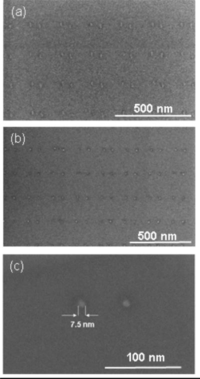
SEM images of the array of AuPd dots (a) after lift-off and (b) + (c) after annealing.
III. Biofunctionalization
The metal nanopatterns were functionalized with biological ligands in order to achieve specific binding of the desired proteins. In the case of gold or gold alloy (e.g., AuPd), the dots were functionalized by a mixed alkane-thiol self-assembled monolayer (SAM) of ethylene-glycol-undecylthiol and biotinylated ethylene-glycol-undecylthiol to which any peptide can be bound via an avidin linkage.13
Because each avidin tetramer has an approximate size of 5 nm20, we expect that on average, only one, but no more than 2 will attach to each 5–8 nm dot. In our earlier work13 we described the surface chemistry required for biofunctionalization. The overall process includes a passivation of the unpatterned glass against non-specific binding with a polyethylene-glycol (PEG) silane, chemical attachment of biotin to the AuPd, followed by the attachment of avidin to the chemisorbed biotin molecules. The last step in the biofunctionalization is the exposure of the functionalized arrays to the solution of biotinylated molecules of fibronectin RGD motif.
In order to verify the avidin linkage to the biotinylated AuPd patterns, we have tagged the avidin with a fluorescent marker. The selective binding of avidin can be seen in Fig. 6(a), which shows an optical microscope image of the NIL template used for the sample fabrication. An array of dots with 90 nm intra-pair spacing is shown, The patterned area consists of a 6 × 6 array of smaller fields (the varying gaps visible in the array are caused by stitching errors in the e-beam patterning of the NIL template). Figure 6(b) shows a Total Internal Reflectance Fluorescence (TIRF) microscopy image of the same area on an imprinted sample after bio-functionalization with the mixed SAM and fluorescently labeled avidin. The strong fluorescence signal appears only on the areas patterned with Au/Pd nano-dots, and the entire fluorescence image is an inverse replica of the NIL template in Fig. 6(a), including the stitching errors. Similar fluorescence images were observed on the areas patterned with dot pairs with different intra-pair spacing.
Figure 6.
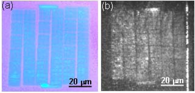
(a) Optical microscope image of “b=90 nm” area in the NIL template, (b) same area on the imprinted glass sample, bio-functionalized with thiolated biotin and fluorescence-tagged avidin.
IV. Cell Spreading
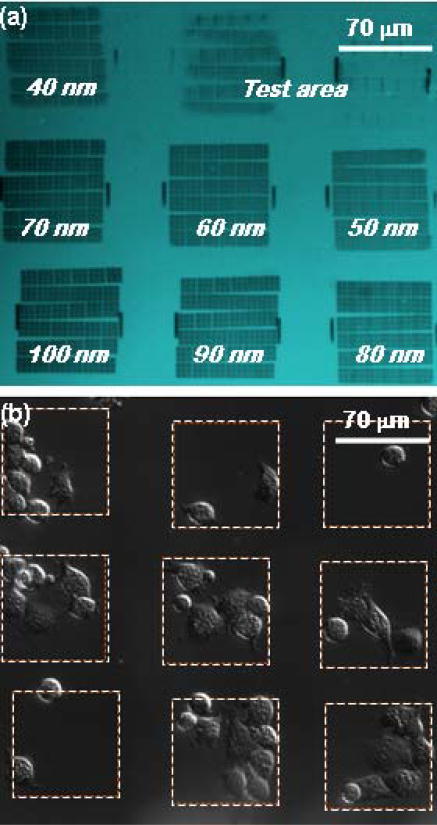
3T3 fibroblast cells were used for initial demonstration of cell attachment to the biofunctionalized patterns. Arrays of AuPd dots pairs, patterned on glass coverslips and biofunctionalized with fibronectin RGD 7–10 motifs through biotin-avidin-biotin linkage were used in this assay. Figure 7(a) shows an optical microscope image of the patterned arrays before lift-off. Each array is 70 μm × 70 μm in area, and the intra-pair spacing varies from 40nm to 100 nm. Figure 7(b) shows cells on the same areas 1/2 hour after plating. Cells can be seen to have spread on most of the patterned domains, having migrated from the PEG-passivated glass surface. These initial results demonstrate the viability of our approach. However, before definitive conclusions can be reached regarding the effects of ligand spacing on cell spreading, more comprehensive experiments are required.
Figure 7.
(a) Optical microscopy of the patterned arrays before lift-off. (b) Cells spreading on the patterned substrate, bio-functionalized with RGD. (The test area consists of features patterned for lithography control purposes and is not measured in cell spreading experiments.)
5. Conclusions
We have developed a technique based on nanonimprint lithography for defining arrays of ultra-small domains for the attachment of single protein molecules. Thermal NIL coupled with an angle-evaporated hard mask and thermal annealing was used to pattern arrays of metal features with sub-10 nm dimension, arranged in a precise and controlled geometry,. The arrays were functionalized with fibronectin RGD motif molecules, and their implementation in the fundamental in-vitro study of cytoskeletal protein binding interactions in living cells has been demonstrated.
Acknowledgments
This work was supported primarily by the National Science Foundation under award number NSF EF-05-07086, as well as by the National Institutes of Health through the NIH Roadmap for Medical Research under award number PN2 EY 016586. Additional support from the Nanoscale Science and Engineering Initiative of the National Science Foundation under NSF Award Number CHE-0641523 and by the New York State Office of Science, Technology, and Academic Research (NYSTAR)″ is also gratefully acknowledged. We are grateful to the Columbia University Center for Electron Transport in Molecular Nanostructures and the Center for Nanostructured Materials for making their processing facilities available for this work.
References
- 1.Stevens MM, George JH. Science. 2005;310:1135. doi: 10.1126/science.1106587. [DOI] [PubMed] [Google Scholar]
- 2.Galbraith CG, Yamada KM, Sheetz MP. J Cell Bio. 2002;25:695. doi: 10.1083/jcb.200204153. [DOI] [PMC free article] [PubMed] [Google Scholar]
- 3.Gilespie PG, Walker RG. Nature. 2001;413:194. doi: 10.1038/35093011. [DOI] [PubMed] [Google Scholar]
- 4.Maheshawari G, Brown G, Lauffenburger DA, Wells A, Griffith LG. J Cell Sci. 2000;113:1677. doi: 10.1242/jcs.113.10.1677. [DOI] [PubMed] [Google Scholar]
- 5.Koo LY, Irvine DJ, Mayes AM, Lauffenburger DA, Griffith LG. J Cell Sci. 2002;115:1423. doi: 10.1242/jcs.115.7.1423. [DOI] [PubMed] [Google Scholar]
- 6.Miyamoto S, Akiyama SK, Yamada KM. Science. 1995;267:883. doi: 10.1126/science.7846531. [DOI] [PubMed] [Google Scholar]
- 7.Jiang G, Giannone G, Critchley DR, Fukumoto E, Sheetz MP. Nature. 2003;424:334. doi: 10.1038/nature01805. [DOI] [PubMed] [Google Scholar]
- 8.Critchley DR, Gingras AR. J Cell Sci. 2008;121:1345. doi: 10.1242/jcs.018085. [DOI] [PubMed] [Google Scholar]
- 9.Arnold M, Cavalcanti-Adam EA, Glass R, Blummel J, Eck W, Kantlehner M, Kessler H, Spatz JP. ChemPhysChem. 2004;5:383. doi: 10.1002/cphc.200301014. [DOI] [PubMed] [Google Scholar]
- 10.Glass R, Arnold M, Blummel J, Kuller A, Muler M, Spatz JP. Adv Funct Mater. 2003;13:569. [Google Scholar]
- 11.Erb EM, Tangemann K, Bohrmann B, Muller B, Engel J. Biochem. 1997;36:7395. doi: 10.1021/bi9702187. [DOI] [PubMed] [Google Scholar]
- 12.Xiong JP, Stehle T, Zhang R, Joachimiak A, Frech M, Goodman SL, Arnaout MA. Science. 2002;296:151. doi: 10.1126/science.1069040. [DOI] [PubMed] [Google Scholar]
- 13.Cherniavskaya O, Chen CJ, Heller E, Sun E, Provezano J, Kam L, Hone J, Sheetz MP, Wind SJ. J Vac Sci Technol B. 2005;23:2972. [Google Scholar]
- 14.Chou SY, Krauss PR, Zhang W, Guo L, Zhuang L. J Vac Sci Technol B. 1997;16:2897. [Google Scholar]
- 15.Hua F, Sun Y, Gaur A, Meitl M, Bilhaut L, Rotkina L, Wang JF, Geil P, Shim M, Rogers JA, Shim A. Nano Lett. 2004;4:2467. [Google Scholar]
- 16.Carlberg P, Graczyk M, Sarwe EL, Maximov I, Beck M, Montelius L. Microelectron Eng. 2003 ;67–68:203. [Google Scholar]
- 17.Tao J, Chen Y, Zhao X, Malik A, Cui Z. Microelectron Eng. 2005;78–79:665. [Google Scholar]
- 18.Namatsu H, Takahashi Y, Yamazaki K, Yamaguchi T, Nagase M, Kurihara K. J Vac Sci Technol B. 1998;16:69. [Google Scholar]
- 19.Schvartzman M, Mathur A, Hone J, Jahnes C, Wind SJ. Appl Phys Lett. doi: 10.1063/1.2944997. in press. [DOI] [PMC free article] [PubMed] [Google Scholar]
- 20.Pugliese L, Coda A, Malcovati M, Bolognesi M. J Mol Bio. 1993;231:698. doi: 10.1006/jmbi.1993.1321. [DOI] [PubMed] [Google Scholar]


