Abstract
The new Solid State X-ray Image Intensifier (SSXII) is being designed based on a modular imaging array of Electron Multiplying Charge Couple Devices (EMCCD). Each of the detector modules consists of a CsI(Tl) phosphor coupled to a fiber-optic plate, a fiber-optic taper (FOT), and an EMCCD sensor with its electronics. During the optical coupling and alignment of the modules into an array form, small orientation misalignments, such as rotation and translation of the EMCCD sensors, are expected. In addition, barrel distortion will result from the FOTs. Correction algorithms have been developed by our group for all the above artifacts. However, it is critical for the system’s performance to correct these artifacts in real-time (30 fps). To achieve this, we will use two-dimensional Look-Up-Tables (LUT) (each for x and y coordinates), which map the corrected pixel locations to the acquired-image pixel locations. To evaluate the feasibility of this approach, this process is simulated making use of parallel coding techniques to allow real-time distortion corrections for up to sixteen modules when a standard quad processor is used. The results of this simulation confirm that tiled field-of-views (FOV) comparable with those of flat panel detectors can be generated in ~17 ms (>30 fps). The increased FOV enabled through correction of tiled images, combined with the EMCCD characteristics of low noise, negligible lag and high sensitivity, should make possible the practical use of the SSXII with substantial advantages over conventional clinical systems.
Keywords: ALG, SIM, SYS, DET, LabVIEW, Graphical-User-Interface, Region-of-Interest, Fluoroscopy, Angiography, High-Resolution
1. INTRODUCTION
Rapid progress in Endovascular Image Guided Interventions (EIGI) has increased the demand for improved quality in medical imaging, such as higher spatial resolution, increased sensitivity, negligible lag, wider dynamic range and higher frame rates. Furthermore, the improved but at the same time more complex EIGI methods [1, 2, 3, 4, 5] along with the novel x-ray imaging detectors [5, 6, 7, 8, 9] are vital tools for the treatment of cerebrovascular diseases (CVD) [3], such as aneurysms and vessel stenoses. Up-to-date high-resolution imaging can be done using individual detectors having relatively small fields of view (FOVs). To obtain large FOV high resolution imaging data, these detectors can be arranged into arrays. One of these newest x-ray detectors with enhanced fluoroscopic imaging capabilities is the new Solid State X-ray Image Intensifier (SSXII)[6, 9]; an image receptor which is characterized by all the above image quality factors and which at the same time offers a large field of view (FOV) when an array of modules is used. However, mechanical limitations of the optical coupling and positioning the modules to form the array may result in the sub-images (from the individual detectors) being rotated and translated relative to each other. Furthermore, barrel distortion is expected to occur due to the fiber-optic tapers (FOT). These misalignments and distortions will cause discontinuities and artifacts on the final image which have to be corrected in real time (30 fps) in order to provide a clinically usable image. In this paper, the system design and the related simulation results of a real-time solution to the above problem will be presented. Furthermore, an implementation of the distortion corrections in our pre-designed radiographic software [10] will be discussed. Such implementation is necessary due to the ability of the software to clinically automate the radiographic procedures for the above complex EIGI methods and hence, simplify the job of the interventionalist for better and quicker treatment and more accurate diagnoses. Finally, it will be shown how it is possible to take advantage of parallel processing and enable real-time image distortion corrections for up to sixteen SSXII modules on a standard personal computer (PC) with a quad central processing unit (CPU).
2. METHODS AND MATERIALS
2.1 SSXII Detector
Each of the SSXII detector modules, which are currently under development, consists of a CsI(Tl) input phosphor coupled to a fiber-optic plate, a fiber-optic taper (FOT), and an EMCCD sensor with its front-end electronics. The EMCCD sensor that we use (figure 1) is the 1k × 1k pixels, TC285SPD-B0 Impactron device [11] with an 8.0 μm pixel size. This sensor has electron multiplication ability where light generated charge is multiplied in several stages within the readout serial register before it reaches the output amplifier. In this way, signal-to-noise ratio is improved, and the SSXII detector adds its huge intrinsic gain to the image quality benefits discussed in the introduction. The SSXII modules have been designed from individual EMCCD sensors in such a way so that they will be placed next to each other in a rectangular array, and they will be networked together using a digital signal processor (DSP) in order to merge the modular images into a unified one with dimensions of 1k × 1k pixels. In this paper, we are assuming the use of four modules placed in a 2 × 2 squared array (figure 2), where each module will be operating in 2 × 2 binning mode in order to achieve the desired image of 1k × 1k pixels. As mentioned above, the distortions and misalignments need to be corrected in real time before the final image is displayed. Because the SSXII detector is currently under development, the real-time implementation of distortion and orientation corrections was simulated.
Figure 1.
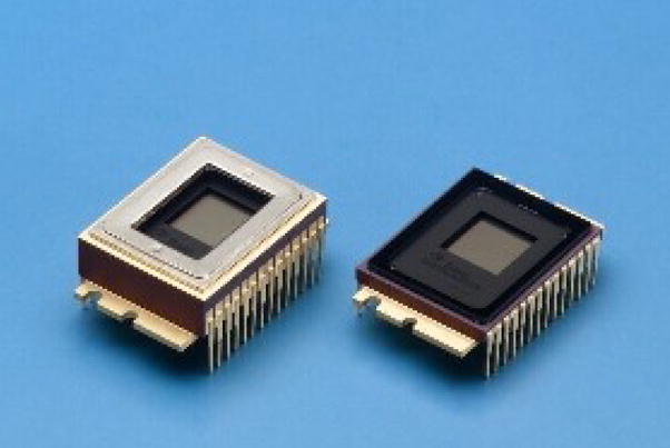
The TC285SPD EMCCD sensors [11] with (left) and without (right) peltier cooler
Figure 2.
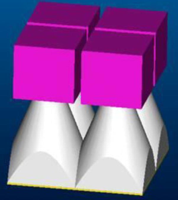
The SSXII modular array. (purple cubes) EMCCD modules. (white truncated pyramids) FOTs.
2.2 Simulation Setup
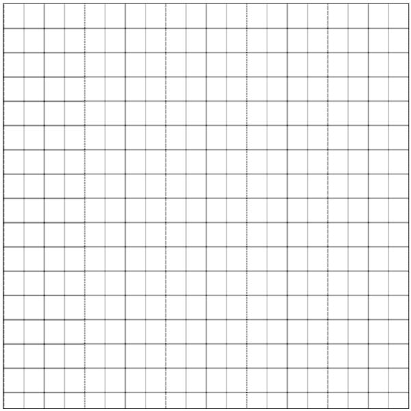
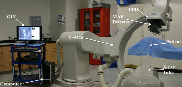
We distort and misalign a wire mesh calibration image as well as an acquired image using the same parameters to simulate the images captured by the EMCCD modules. The distortions and misalignments are determined by software analysis of the simulated calibration image, and corrections are then applied to the simulated acquired image. Figure 3 shows a wire mesh phantom image that we have used to test and evaluate the corrections. We acquired images to be used in the simulation using a detector with the same image characteristics as those of the SSXII (Micro Angiographic Fluoroscopic Detector [1,5,7,17] (MAF), 12 bit, 1k × 1k pixels, progressive scan frame transfer at 30 fps). The MAF detector, which is mounted on a retractable arm, is inserted into the x-ray beam of a C-arm angiographic system between the Flat Panel Detector (FPD) and the patient. Figure 4 shows the experimental setup of an animal experiment in which Roadmap images were acquired for use in the simulation.
Figure 3.
Wire mesh simulation image
Figure 4.
MAF system setup for acquiring images for simulating the distortion and misalignment corrections
2.3 Distortion Correction Algorithms
Methods for determining and correcting the barrel distortion and the orientation and translation misalignments have been developed earlier by our group [12, 13] using a known wire mesh phantom. After identifying the mesh crossing point positions, the distortion and misalignment parameters are determined. To determine the distortion, the crossing point data are fit using a radially symmetric function. To determine the relative rotation, the vectors between the crossing points in each image are calculated, and the angles between corresponding vectors in the various images are determined using cross products. To determine the translation, vectors between reference structures are used. These parameters are used to determine the pixel positions in the acquired distorted, misaligned image which correspond to those in the to-be-generated corrected image. For each pixel in the corrected image, the location in the acquired image is determined, and the value to be placed in that pixel is calculated using bilinear interpolation of the pixel values in the acquired image. The above corrections were found to provide accuracy within 1% for distortion, within 0.1 degree for rotation and within 1 pixel for translation.
2.4 Look-Up-Table Transformations
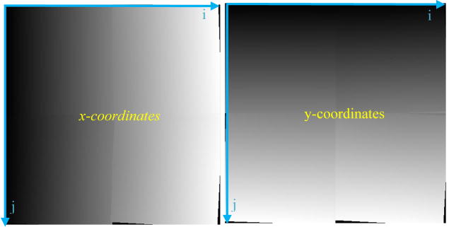
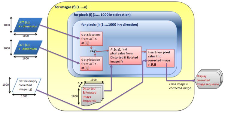
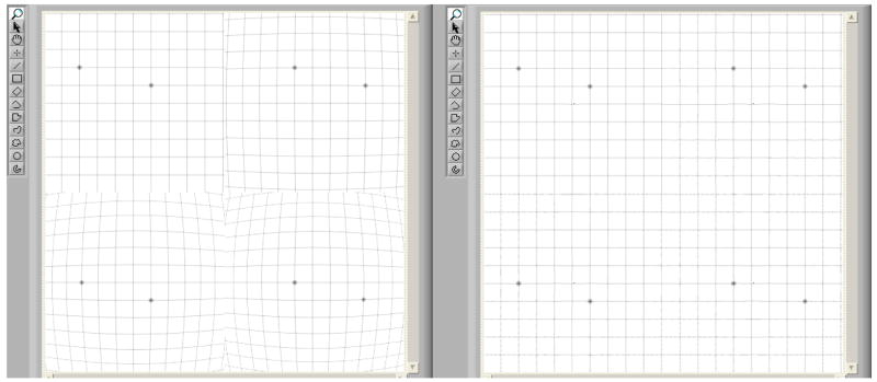
After carefully placing and fixing the SSXII modules together into an array, all the expected distortions and misalignments discussed above will be constant and will not change. The correction parameters will be experimentally determined, and the mapping relating pixels in the corrected image to those in the acquired image will be generated. From this mapping, we can derive the two-dimensional LUTs (figure 5) that contain the coordinates in the distorted image corresponding to each pixel in the corrected image. As shown in figure 7, we can then use these LUTs to allow rapid generation of the corrected images. These LUTs will be valid for corrections of all subsequently acquired images, assuming the SSXII detector modules are not changed. Should any SSXII module be replaced, new LUTs will be determined by reapplying the distortion correction algorithms.
Figure 5.
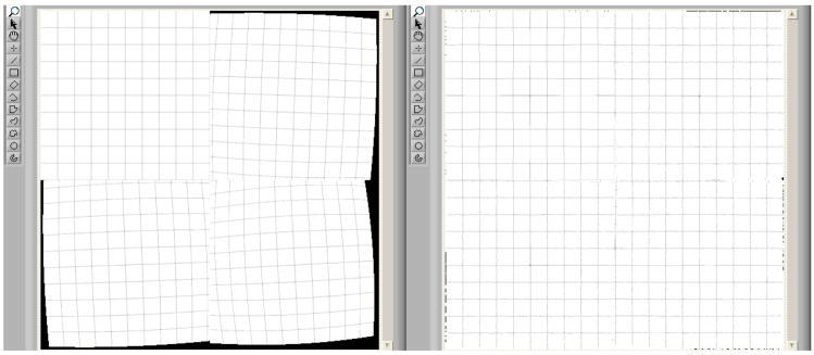
Two-dimensional LUTs for the x (left array) and y (right array) coordinates provide the mapping of pixel locations in the new image to those in the original acquired image. Each coordinate LUT is represented here as an array of 4 graylevel images for 4 sub-images wherein the graylevel values represent the coordinate values (x,y) on the acquired (distorted) image where the image intensity pixel values that have to be placed on the corrected image are located (i,j).
Figure 7.
Flowchart of distortion correction method using LUTs
2.5 Simulation of Distortion Correction
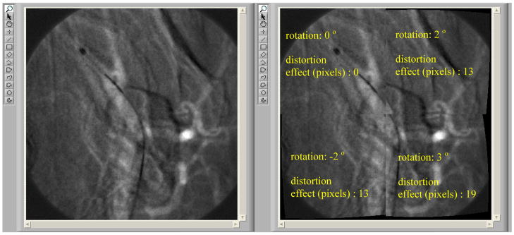
For the simulation, we divided our MAF roadmap images in four quadrants, and we artificially distorted each one with a different level of distortion and rotation (figure 6).
Figure 6.
MAF Roadmap images, before (left) and after (right) distortions and rotations are applied
These images with four quadrants represent images coming from the four SSXII modules as they satisfy the resolution and data size criteria of the SSXII modular images. The two LUT’s (one for the x coordinate and one for the y coordinate) which contain the coordinates of the locations in the acquired image for each pixel in the corrected image were used by our Labview-based software [10] to generate corrected images for display as a clinically appropriate image sequence. Figure 7 shows a flowchart of the distortion correction method using the LUTs.
In this simulation we have assumed that the centers of rotations of the four sub-images are at the center of the image; hence, we do not take into account possible translation of the actual SSXII modules. However, should translation need to be corrected, the correction will be included in the same 2D LUTs, and thus our system timing performance will remain the same as the current simulation.
2.6 Task Parallelism
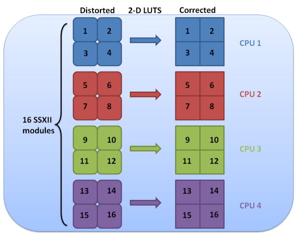
The LUTs used in the above simulation were duplicated in four independent LUTs for x-dimension and four independent LUTs for y-dimension, and have been included in the data-processing stream. Task Parallelism (a parallel-coding technique that enables independent execution of threads running in parallel on different processors) was used to increase the number of the SSXII modules that we can perform correction to 16. For this simulation, a standard 2.4 GHz quad processor was used, and each processor was set to handle the distortion correction for 4 sub-images coming from 4 SSXII modules. The software was able to correct in real-time all 16 sub-images. Figure 8 shows the task parallelism flow diagram of the real-time distortion-correction procedure for the 16 modules.
Figure 8.
Task parallelism flow diagram for 16 SSXII modules handled by a quad processor
2.7 Distortion Correction Implementation in the data-processing stream
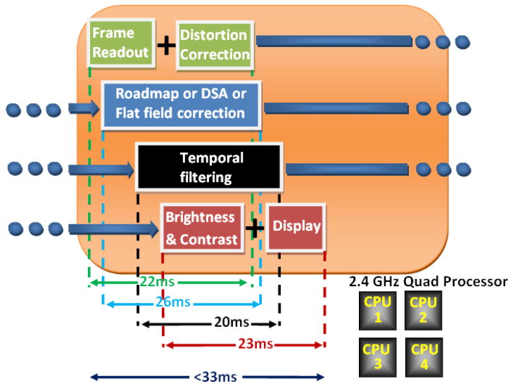
The LUT-based distortion-correction software is included in the processing data stream of a user-friendly GUI as part of the SSXII detector system. The performance of the SSXII will be evaluated under actual EIGI imaging procedures such as fluoroscopy, fluoroscopic roadmapping, angiography, digital subtraction angiography (DSA), and rotational Region-of-Interest Cone-Beam Computed Tomography [14, 15, 16] (ROI-CBCT). In addition, the software will be able to handle, along with the distortion correction and the above radiographic procedures, other imaging processing tasks such as flat-field correction, brightness and contrast control, last-frame hold in fluoroscopy, looped play-back of the acquired images in angiography, recursive temporal filtering for noise reduction, indexed storage of images, automatic multiplication gain control, and pixel binning of the EMCCD sensors. Finally, it will be responsible for the required synchronization of the detector and the x-ray exposures. In order to accomplish real-time implementation of all the above processes, parallel pipeline coding has been designed in the software of the GUI. Various instructions can overlap in execution and be handled by different processors. Figure 9 shows how the pipeline stages have been balanced in order to optimize data throughput. Operations on images are being handled at the pixel level. This gives us the ability to start the subsequent operation on a different processor before the current one is completed.
Figure 9.
Instruction Pipelining of frame readout, distortion correction, other image processing and display
3. RESULTS AND DISCUSSION
After implementing the LUT distortion correction method in the radiographic processing software on our wire mesh image, we were able to correct our simulated sub-images from any distortion and display the merged corrected image in about 17 ms time cycle on a 2.4 GHz processor. This result indicated that image correction using LUTs can run in the desired real time speed of 30 fps. The LUTs were able to correct barrel distortion with no visible artifacts. Figure 10 shows an image (left) consisting of four distorted sub-images, each with a different level of distortion and the corrected image (right). Figure 11 shows the same distorted image (left) with different degrees of rotation added to each sub-image and the corrected image (right). In this case, we observe minor artifacts due to the large amounts of distortion and rotation added to the sub-images. However, in the real case, we expect the barrel distortion of the fiber optic taper to be less significant and the amount of rotation to be kept as low as possible during the careful placement of the SSXII modules. In this paper, we intentionally implement such large amounts of distortion and rotation in order to deliver a more visible result to the reader. The timing needed to correct both barrel distortion and rotation stayed at 17 ms.
Figure 10.
Distortion correction on a simulated wire mesh image (Distorted on the left; corrected on the right)
Figure 11.
Distortion & rotation correction on a simulated wire mesh image (Distorted & rotated on the left; corrected on the right)
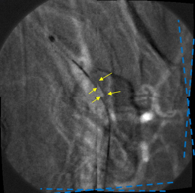
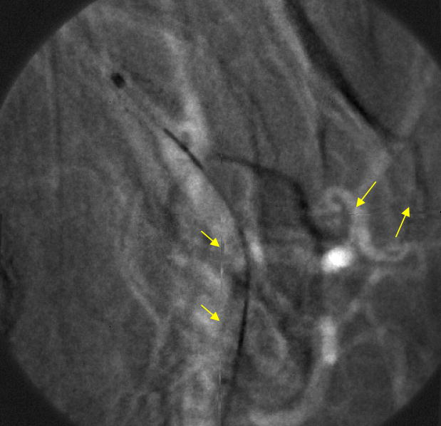
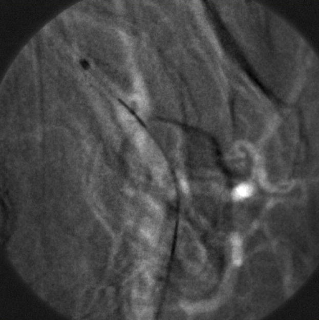
This result clearly demonstrates the successful performance of the LUTs distortion correction method on a still image. However, it was important to perform the same experiment on a sequence of images, in order to confirm an absence of visible artifacts during random object movement. So, the next step was to generate simulated images using image sequences that were acquired with the MAF detector while a stent was expanded in a rabbit and a catheter was moving in the animal’s vessels crossing the boundaries between the sub-images. The images were divided into four sub-images which were then distorted. An example of a generated fluoroscopic roadmapping image is shown in Figure 12. The distortion and discontinuities near the boundaries of the sub-images can be clearly seen. Using the LUTs derived from the wire-mesh phantom, the image was corrected. The corrected image is shown in Figure 13, where the distortion and discontinuity artifacts are almost eliminated. As was stated above, we are expecting to almost perfectly correct any artifacts after keeping the distortion and rotation amounts as small as possible. In reality, the barrel distortion for a FOT that we are planning to use was measured to be 6.5 pixels maximum which is 2 and 3 times less than the distortions we have applied in our simulation image. Figure 14 shows the original image (before distortion and rotation) which is comparable with the corrected image of figure 13.
Figure 12.
Distorted and Rotated MAF Image (see arrows and angle lines)
Figure 13.
Corrected MAF Image
Figure 14.
Original MAF (before distortion has been applied)
Despite the minor artifacts (arrows) on the corrected image of figure 14, the vessels and the catheter are continuous between the sub-images and they are not distorted.
5. CONCLUSIONS
A new distortion and orientation correction method for a tiled EMCCD-based Solid State X-ray Image Intensifier has been designed and demonstrated and the following conclusions have been made:
Real-time implementation of distortion corrections for the SSXII was achieved with the use of LUTs.
The final corrected image has image quality comparable to the original image. Minor artifacts are seen when large distortions are simulated which will need to be eliminated in future implementations.
The ability to handle more modules by parallel processing coding enables a larger FOV.
Pipelining introduces the ability to enable in real time all image processing requirements along with the distortion and alignment corrections in the radiographic processing software.
The increased FOV with the EMCCD characteristics of low noise, negligible lag and high sensitivity should enable the practical use of the SSXII with its substantial benefits over conventional clinical systems.
Acknowledgments
This work was supported in part by the NIH Grants R01EB008425, R01NS43924, R01EB002873 and an equipment grant from Toshiba Medical Systems Corp. that also supplied the new detector support.
References
- 1.Ionita C, Keleshis C, Patel V, Yadava GK, Hoffmann KR, Bednarek DR, Jain A, Rudin S. Implementation of a high-sensitivity Micro-Angiographic Fluoroscope (HS-MAF) for in-vivo endovascular image guided interventions (EIGI) and region-of-interest computed tomography (ROI-CT) Proc SPIE Medical Imaging. 2008. pp. 6918–69181I. http://www.pubmedcentral.nih.gov/articlerender.fcgi?tool=pubmed&pubmedid=18958294. [DOI] [PMC free article] [PubMed]
- 2.Rudin S, Bednarek DR, Hoffmann KR. Endovascular image guided interventions (EIGIs) Med Phys. 2008;35(1):301–309. doi: 10.1118/1.2821702. [DOI] [PMC free article] [PubMed] [Google Scholar]
- 3.Ionita C, Rudin S, Bednarek DR, Hoffmann KR. Microangiographic image-guided localization of a new asymmetric stent for treatment of cerebral aneurysms. Proc SPIE. 2005;5744:354–365. doi: 10.1117/12.594789. [DOI] [PMC free article] [PubMed] [Google Scholar]
- 4.Ionita C, Dohatcu A, Sherman J, Keleshis C, Paciorek A, Hoffmann K, Bednarek DR, Rudin S. Angiographic analysis of animal model aneurysms treated with novel polyurethane asymmetric vascular stent (P-AVS): feasibility study. SPIE. 2009 Mar;7262–52 doi: 10.1117/12.812628. in print. [DOI] [PMC free article] [PubMed] [Google Scholar]
- 5.Yadava GK. PhD Dissertation submitted to Department of Physics. SUNY/Univ.; Buffalo: 2007. Development and evaluation of a new High Sensitivity, Region-of-Interest, x-ray imaging system for neuro-interventional applications; pp. 52–65. [Google Scholar]
- 6.Kuhls-Gilcrist AT, Yadava GK, Patel V, Jain A, Bednarek DR, Rudin S. The solid-state x-ray image intensifier (SSXII): an EMCCD-based x-ray detector. Proc SPIE Medical Imaging. 2008;6913:69130K. doi: 10.1117/12.772724. http://www.pubmedcentral.nih.gov/articlerender.fcgi?tool=pubmed&pubmedid=18836568. [DOI] [PMC free article] [PubMed] [Google Scholar]
- 7.Rudin S, Kuhls-Gilcrist AT, Yadava GK, Josan G, Wu Y, Chityala R, Rangwala H, Ionita C, Hoffmann KR, Bednarek DR. New light-amplifier-based detector designs for high spatial resolution and high sensitivity CBCT mammography and fluoroscopy. Proc SPIE Vol. 2006;6142:61421R. doi: 10.1117/12.649501. [DOI] [PMC free article] [PubMed] [Google Scholar]
- 8.Kuhls-Gilcrist AT, Patel V, Ionita C, Noel P, Walczak A, Rangwala H, Hoffmann KR, Rudin S. New microangiography system development providing improved small vessel imaging, increased contrast-to-noise ratios, and multiview 3D reconstructions. Proc SPIE Vol. 2006;6142:61423M. doi: 10.1117/12.653654. [DOI] [PMC free article] [PubMed] [Google Scholar]
- 9.Kuhls-Gilcrist AT, Yadava G, Patel V, Bednarek DR, Rudin S. Progress in electron-multiplying CCD (EMCCD) based high-resolution high-sensitivity x-ray detector for fluoroscopy and radiography. Proc SPIE Vol. 2007;6510:65101C. doi: 10.1117/12.713140. [DOI] [PMC free article] [PubMed] [Google Scholar]
- 10.Keleshis C, Ionita C, Yadava G, Patel V, Bednarek DR, Hoffmann KR, Verevkin A, Rudin S. LabVIEW graphical user interface for a new high sensitivity, high resolution micro-angio-fluoroscopic and ROI-CBCT system. SPIE. 2008 Mar;6913:69135A. doi: 10.1117/12.769630. http://www.pubmedcentral.nih.gov/articlerender.fcgi?tool=pubmed&pubmedid=18836570. [DOI] [PMC free article] [PubMed] [Google Scholar]
- 11.Texas Instruments. TC285SPD-30,-31/TC285SPD-B0 2/3-inch 1M-pixel IMPACTRONTM CCD. 2008. Retrieved December 28, 2008, from : http://web.tij.co.jp/jsc/docs/disp/eng/impact/tc285-e.htm.
- 12.Hamwi H, Lee JW, Hoffmann KR, Rudin S, Verevkin A. Distortion, Orientation, and Translation Corrections of Tiled EMCCD Detectors for the New Solid State X-ray Image Intensifier (SSXII) SPIE. 2008 Mar;6913:69133T. doi: 10.1117/12.769633. [DOI] [PMC free article] [PubMed] [Google Scholar]
- 13.Hamwi H, Hoffmann KR, Dinu P, Keleshis C, Verevkin A, Rudin S. Distortion and orientation correction of tiled EMCCD detector images. International Journal of Computer Assisted Radiology and Surgery. 2007;2(Suppl 1):131–3. [Google Scholar]
- 14.Chityala R. PhD Dissertation submitted to Department of Mechanical and Aerospace Engineering. SUNY/Univ.; Buffalo: 2007. Region of Interest Cone Beam Computed Tomography (ROI-CBCT) [Google Scholar]
- 15.Chityala R, Hoffmann KR, Bednarek DR, Rudin S. Region of interest (ROI) computed tomography (CT): comparison with full field of view (FFOV) and truncated CT for a human head phantom. Proc SPIE. 2005;5745:583–590. doi: 10.1117/12.595430. [DOI] [PMC free article] [PubMed] [Google Scholar]
- 16.Rangwala H, Chityala R, Rudin S, Hoffmann K. A Portable Test Platform for Image Acquisition and Calibration for Cone Beam Computed Tomography (CBCT) and Region of Interest CBCT (ROI-CBCT) On a Commercial X-Ray C-Arm System. Medical Physics. 2006;33(6):1997–1998. [Google Scholar]
- 17.Yadava GK, Rudin S, Kuhls-Gilcrist AT, Bednarek DR. Generalized objective performance assessment of a new high-sensitivity microangiographic fluoroscopic (HSMAF) imaging system. Proc SPIE Medical Imaging. 2008;6913:69130U. doi: 10.1117/12.769808. http://www.pubmedcentral.nih.gov/articlerender.fcgi?tool=pubmed&pubmedid=18836567. [DOI] [PMC free article] [PubMed] [Google Scholar]


