Abstract
Rotating spiral waves have been observed in numerous biological and physical systems. These spiral waves can be stationary, meander, or even degenerate into multiple unstable rotating waves. The spatiotemporal behavior of spiral waves has been extensively quantified by tracking spiral wave tip trajectories. However, the precise methodology of identifying the spiral wave tip and its influence on the specific patterns of behavior remains a largely unexplored topic of research. Here we use a two-state variable FitzHugh–Nagumo model to simulate stationary and meandering spiral waves and examine the spatiotemporal representation of the system’s state variables in both the real (i.e., physical) and state spaces. We show that mapping between these two spaces provides a method to demarcate the spiral wave tip as the center of rotation of the solution to the underlying nonlinear partial differential equations. This approach leads to the simplest tip trajectories by eliminating portions resulting from the rotational component of the spiral wave.
Spiral waves are the subject of intense investigation and occur in various nonlinear media.1, 2, 3, 4, 5, 6, 7 The wave tip serves as an organizing center that often appears to meander in epicyclic patterns; each epicyclic “petal” typically represents one rotation of the meandering spiral. These patterns are usually represented in a “flower garden” arrangement8, 9, 10, 11, 12 and the associated dynamics have important implications, e.g., dangerous cardiac arrhythmias are the result of the movement and stability of rapidly rotating spiral waves propagating in the heart.13 The instantaneous wave-tip location and its trajectory are identified by methodologies whose theoretical basis and limitations have not been adequately addressed. Identifying the tip based on the spiral wave solution of the underlying equations eliminates one epicycle per spiral-wave rotation, i.e., all petals were “plucked” from each flower we “picked.” Just as Copernican astronomy eliminated the epicyclic descriptions of planetary orbits of the Ptolemaic system,14 so our model shows that extensively studied epicycles of a meandering spiral-wave tip arise from inappropriate origin choice.
INTRODUCTION
Occasionally in science the complexity of an explanation of a particular phenomenon is sensitive to the choice of a reference point or coordinate system, and a choice of coordinates that properly reflects the dynamics of the system simplifies its description. A notable example is the heliocentric Copernican replacement of Ptolemy’s geocentric model of planetary motion—the choice of the sun as the origin ultimately led to elliptic rather than epicyclic orbital descriptions.14 Another example is wave propagation, in which a moving coordinate system can reduce a partial differential equation (PDE) that depends upon both space and time to an ordinary differential equation. For a given system, the challenge is to determine whether a properly chosen coordinate transformation will simplify the explanation.
In nature, rotating spiral waves are found in galaxies, storms, chemical systems, liquid crystal, slime molds, the brain, and the heart.1, 3, 4, 5, 6, 7, 15, 16, 17, 18 The tip of a spiral wave can meander along open or closed trajectories whose dependence on system parameters has been described in terms of a flower garden composed of circles and complex epicyclic trajectories.8, 9, 10, 11, 12 The motion of the tip is particularly important in the heart, where the transition from a stable to a drifting or meandering tip and then to spiral wave breakup may correspond to the transition from stable to polymorphic electrical arrhythmias and then to fibrillation and sudden cardiac death.19, 20 Given the importance of spiral wave dynamics, it is important to characterize the tip motion accurately. For example, a robust tip identification algorithm could be used to quantify the number and location of spiral waves, which is essential to characterizing complex spiral wave dynamics (e.g., cardiac fibrillation)13, 21 and their termination (e.g., defibrillation).22 In this paper, we explore whether the reported flower gardens truly reflect the underlying dynamics, or in fact are an artifact of the choice of coordinate system and tip-identification parameters.
Identifying spiral wave tip trajectories
Over the years, numerous investigators have identified the tip of spiral waves using a variety of algorithms.23 A common method to determine tip location is to compute where the isocontours of two-state variables intersect.9, 12, 24, 25 This method allows for the identification of the wave tip at each instant of time but suffers from the lack of clear criteria for selecting the particular isocontours and the need to know the spatiotemporal behavior of two-state variables. A similar method involves choosing a particular isocontour value of one state variable and finding the point on that contour which exhibits a zero time derivative.26 Alternatively, the site of maximal wave-front curvature on a particular isocontour can be used to track tip movement.10 Both of these approaches alleviate the need for two-state variables (since a single isocontour, e.g., transmembrane potential isocontour, is used) but again require the choice of a particular isopotential. Recently, there has been a growing interest in the use of a “state space phase variable” (which requires the choice of an “origin” in state space) to represent spiral wave dynamics and compute topological charge in physical space to allow efficient localization of the phase singularities about which spiral waves rotate.13, 27, 28 The equivalence of the phase and zero-time-derivative approaches has been demonstrated experimentally.29 It is critical to realize that an arbitrary choice of an origin or isocontour value is embedded within each of these techniques. Hence the same technique will produce different tip trajectories depending upon the choice of origin or isocontour,30, 31 and comparison between techniques can be confounded by the different criteria used for tip identification. One might conclude that no uniquely identifiable point truly represents the tip of the spiral wave. This would bring into question the study of the flower gardens of trajectories, each of which has been cultivated using a particular choice of tip-identification parameters.
SIMULATION OF SPIRAL WAVES
We use the classic two-state variable FitzHugh–Nagumo PDE model to simulate stationary and meandering spiral waves,
| (1) |
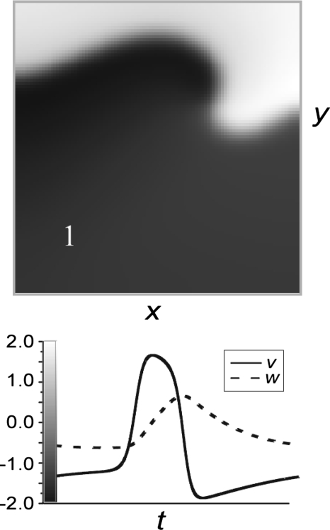
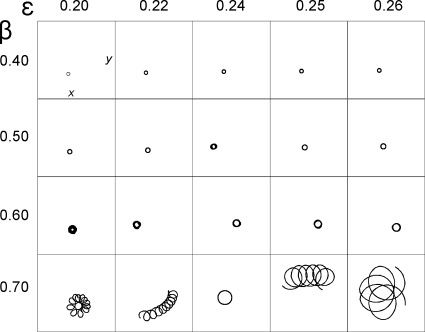
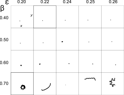
where V is the fast variable, W represents the slow variable, D is the diffusion coefficient, and ε, β, and γ are model parameters. A snapshot of the fast variable V(x,y) and the time course of both V and W at one site are shown in Fig. 1 for one simulation. This model has been used in previous studies of spiral wave tip trajectories.9, 12 A flower garden plot of trajectories for this model as a function of parameters ε and β is shown in Fig. 2. The two-state variable phase method30 was used to compute the trajectories with the origin as (V*=0, W*=0); specifically, a phase variable θ was computed at each site (x,y) according to
| (2) |
where t represents time. This phase variable represents the angular dynamics in state space, i.e., (V,W), in reference to the state space origin (V*,W*). Phase singularities represent the spatial location of the spiral wave tip and are easily identified in physical space (x,y) as sites where the line integral of θ on a closed curve c around a site is nonzero, i.e.,
| (3) |
Iyer and Gray30 showed that the ability to localize phase singularities is not sensitively dependent on the specific choice of state space origin (V*,W*), and Fenton et al.31 showed examples of a minimal effect of isocontour choice on tip trajectories. Nevertheless, to the best of our knowledge, there have been no published reports on the justification of a specific choice of origin. In addition, extending all tip finding methods to fibrillation data should only be done with caution, and with a clear understanding of the algorithm’s limitations and theoretical basis. For example (as we show below) inappropriate origin choice can lead to an error in the identification of the number and lifetime of spiral waves.
Figure 1.
FitzHugh–Nagumo model. (Top) Snapshot of the spatial distribution of the fast variable in physical space, i.e., V(x,y). The greyscale color key is shown in the bottom panel. (Bottom) Dynamics of state variables during one beat, i.e., V(t) and W(t) at the site indicated by the number 1 in the top panel.
Figure 2.
Flower garden (original origin choice). The spiral wave tip trajectories in physical space (x,y) for the FitzHugh–Nagumo model [Eq. 1] as a function of parameters ε and β. Phase was computed according to Eq. 2 and the instantaneous wave tip was identified using Eq. 3. The origin choice in Eq. 2 was (V*=0, W*=0).
THEORY
Here we provide a rationale for choosing a specific state space origin for the definition of θ and hence phase singularity localization. Our goal here is essentially to track the instantaneous center of rotation of a spiral wave. In order to do this, we need to separate the problem into two parts: spiral wave rotation around this center point and translational motion of this center point. This problem is similar to the classic characterization of the rolling motion of a wheel on a plane in which the trajectory of the center of mass follows a straight line but any other point traces out a nonlinear path called a cycloid.
A rotating spiral wave represents one solution to the general nonlinear, reaction-diffusion PDE of the form
| (4) |
where is a vector representing the time and space dependent state variables, represents the nonlinear space-clamped kinetic equations for the variables, and is the diffusion tensor.
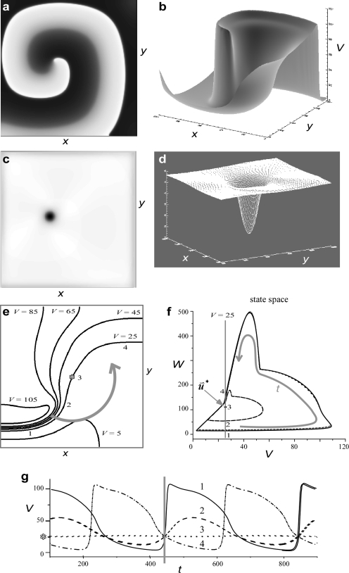
Let us consider a stable, rigidly rotating spiral wave solution to Eq. 4. The reader is encouraged to view Fig. 3 while reading the following text. Such a spiral wave exhibits rotational symmetry around the center of rotation. We will identify the center of rotation in physical space as (x*,y*). At each site (x,y) the state variables will be periodic in time with a period equal to the time for one complete rotation of the spiral wave (Ts) except at site (x*,y*) where no oscillations occur due to rotational symmetry at the center of rotation. We suggest that the value of the state variables at (x*,y*) defined as represents the best choice of the state space origin for the definition of θ [see Eq. 2] and hence phase singularity localization. This point in state space [ for Eq. 1] thus represents the only point where θ is undefined [see Eq. 2]. Typical definitions for the spiral wave tip will, in general, result in closed-loop tip trajectories that are essentially circular for one rotation delineating a spatially two-dimensional (2-D) region called the spiral wave “core.” However, if the point (x*,y*) is chosen for the definition of tip identification, then the tip will be stationary relative to the spiral wave rotation, and the tip trajectory during one rotation will be a point, i.e., spatially zero-dimensional (0-D). A common technique to identify the core is to integrate the variables over one or more rotations and threshold the result.32 If we integrate the state variables over an integer multiple of Ts then the resulting integral yields a surface with a unique minimum at (x*,y*), as shown in Figs. 3c, 3d. This dimensionality difference between the spiral wave core (2-D) and tip (0-D) is very important because the tip can be identified at a time scale less than one rotation but the core cannot.13
Figure 3.
Spatiotemporal dynamics of a stable spiral. (a) Greyscale image snapshot of fast variable (V) depicts a spiral wave rotating counterclockwise. (b) Surface plot of snapshot of V with z-axis representing the value of V. (c) Greyscale image of integral of V over one period; the darker regions indicate lower integral values. (d) Surface plot of integral of V over one period. (e) Contour plot of snapshot of V zoomed in at the center of rotation, which is denoted by an asterisk. (f) Trajectories in state space for the four sites on V=V*=25 contour (horizontal grey line) denoted by numbers 1–4. Since V is the fast variable all trajectories are counterclockwise in state space. (g) Time series of the four sites labeled on (e). The thick vertical gray line indicates the time of snapshot in (e).
Equation 4, in general, does not have an analytical solution because of the nonlinearity of . Following the approach of Barkley,33 one can seek rotationally symmetric spiral wave solutions (with angular velocity ωs=2πTs) of Eq. 4 in a polar coordinate system
| (5) |
where (r,ϕ) represent polar coordinates in physical space. Equation 5 is a nonlinear eigenvalue problem that can be solved for (a rigidly rotating spiral wave solution of all the state variables) and ωs (the corresponding rotation frequency); an associated linear eigenvalue problem can also be solved to determine the stability of these rotating spiral waves.12, 33 Importantly, the state at the center of this rotating spiral wave solution can be computed numerically whether the spiral wave is stationary or not! We propose that the separation of rotational and translational motion can be carried out by defining the instantaneous center of rotation to be that point which has value in the steady state [Eq. 5] and that represents the best choice of state space origin for representing θ [see Eq. 2] and localizing spiral wave tip trajectories [see Eq. 3].
As long as the translational motion of the spiral wave center is “slow,” the environment in which the spiral wave rotates is similar to the steady state environment associated with Eq. 5 and may be considered a perturbation to it. Since the center of rotation is unambiguously defined in the steady state situation, and since at that point contains no oscillations, we hypothesize that the analogous choice in the slowly translating case is also unambiguous, and similarly should have no oscillatory component at the rotation frequency, to some order in the perturbation. Our method is based on a mathematical approach that is strictly valid only for stable, rigidly rotating spiral waves and is similar to Barkley’s translation of the “laboratory” and “rotating coordinate” frames.34 A more mathematically rigorous examination of this topic is contained in Ref. 35.
NUMERICAL METHODS
The eigenmode solver to compute the rigidly rotating spiral wave solution (including ) and ωs (the corresponding rotation frequency) is essentially the same as the one first described by Barkley33 although with a slightly different implementation as described by Otani.12 Briefly, a steady state rotating spiral wave solution was found using a nonlinear eigenmode solver in polar coordinates given initial guesses of both the spiral wave frequency and a spatial pattern of . We determined for the PDE in Eq. 1 for 20 parameter values (ε=0.20,0.22,0.24,0.25,0.26 and β=0.40,0.50,0.60,0.70) using the methodology described previously.12, 33 These values are presented in Table 1 for our two-variable system .
Table 1.
The values of the solution to Eq. 5 at the center of rotation, i.e., for the FitzHugh–Nagumo equation [Eq. 1], as a function of the two model parameters ε and β.
| β | ε | ||||
|---|---|---|---|---|---|
| 0.20 | 0.22 | 0.24 | 0.25 | 0.26 | |
| 0.40 | (−0.637,−0.296) | (−0.644,−0.304) | (−0.651,−0.313) | (−0.654,−0.318) | (−0.658,−0.323) |
| 0.50 | (−0.796,−0.370) | (−0.806,−0.382) | (−0.817,−0.396) | (−0.823,−0.403) | (−0.829,−0.411) |
| 0.60 | (−0.955,−0.444) | (−0.970,−0.463) | (−0.988,−0.486) | (−1.00,−0.500) | (1.01,−0.516) |
| 0.70 | (−1.11,−0.517) | (−1.14,−0.548) | (−1.18,−0.604) | (−1.20,−0.623) | (−1.20,−0.624) |
We simulated stationary and nonstationary spiral waves by integrating Eq. 1 using finite difference methods on a uniform x-y grid. We used the values of D=0.003 and γ=0.8 and varied both ε and β. This PDE was solved on a 500×500 grid with no-flux boundary conditions via Euler integration with grid spacing dx=dy=0.04 and time step dt=0.0004.
RESULTS
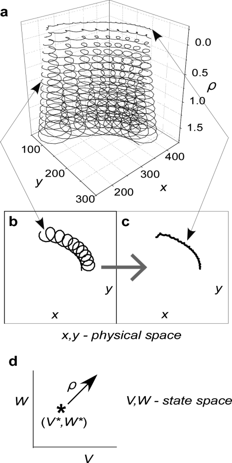
The effect of the origin choice on spiral wave tip trajectories is shown for ε=0.22 and β=0.70 in Fig. 4. The variable ρ represents the distance of the origin choice from ; to study the effect of the choice of the origin, ρ was chosen to vary along the diagonal line V=W [see Fig. 4d]. The spiral wave tip trajectory was a strong function of ρ; as ρ increased from zero, one loop was formed per rotation and these loops increased in size. In other words, one petal per rotation appeared on the tip trajectory for “incorrect” choices of state space origin (ρ≠0). The flower garden in Fig. 2 was reproduced using as the origin choice and is shown in Fig. 5. For all parameter choices of ε and β, the choice of as the origin for the computation of phase (θ) in Eq. 2 resulted in a decrease in complexity of the spiral wave tip trajectories (compare Figs. 52). Circular trajectories became points and looping patterns became lines.
Figure 4.
The spiral wave tip trajectories in the FitzHugh–Nagumo model [Eq. 1; ε=0.22 and β=0.70] as a function of origin choice. (a) Phase was computed according to Eq. 2 and the instantaneous wave tip was identified using Eq. 3. The height of the plot, i.e., the vertical axis, represents the distance from defined as . (b) Spiral tip trajectory for ρ=0.75. (c) Spiral tip trajectory for ρ=0.0. (d) Schematic diagram illustrating choice of ρ along the diagonal in state space.
Figure 5.
Flower garden . The spiral wave tip trajectories in physical space (x,y) for the FitzHugh–Nagumo model [Eq. 1] as a function of parameters ε and β. Phase was computed according to Eq. 2 and the instantaneous wave tip was identified using Eq. 3. The origin choice in Eq. 2 was in contrast to (0,0) in Fig. 2 for the same parameter values of ε and β.
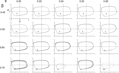
The value of depends on the parameter values of the PDE. That is, changes in ε and β alter the solution to Eq. 5 and hence at the center of rotation. The position of in state space is shown for each parameter set in Fig. 6; is represented as an asterisk and the elliptical curves represent typical dynamics at one site of variables V and W in state space (V,W).
Figure 6.
The dynamics of state variables (V and W) in state space for one site during spiral wave rotation as a function of ε and β. The locations of (see Table 1) are shown as asterisks. For clarity, the axis labels are only shown in the top left plot. The origin (0,0) axes are indicated by dashed lines.
DISCUSSION
The advantage of using in defining state space phase (θ) in Eq. 2 is that it maps to the exact center of rotation for the case that is arguably the best representative and most characteristic of pure spiral wave rotation for the given system, namely, rigid spiral wave rotation around a fixed point. Thus, the point at which is a natural candidate for the definition of the spiral wave tip location—a Copernican choice in an otherwise Ptolemeic situation. Our rationale is consistent with the idea that spiral wave meandering is a perturbation of the steady state solution to Eq. 5.33
The spiral wave tip trajectories for the traditional choice of origin (V=0 and W=0) are not the simplest, as shown in Fig. 2. The value of the origin that produces the simplest pattern corresponds to , as shown in Fig. 5, which in turn depends on the parameter values of the PDE. That is, changes in parameters that produce the observed varieties in the garden also shift the solution to Eq. 5 at the center of rotation, as shown in Fig. 6. Our results demonstrate that if the origin is adjusted in accordance with the parameter shift for each plant in the garden, so as to maintain the correspondence between the solution to Eq. 5 at the center of rotation and the origin, then the garden reduces to a simpler set of curves. We suggest that the origin choice of is the best in the sense that it separates the rotational and translational motions of the spiral wave. One may argue that the flower petals illustrate each spiral wave rotation, and while this can be true, it is not necessarily true. We can see no reason why the spiral wave cannot complete multiple rotations during the time it takes for the trajectory to trace out one complete petal. Since time is parametrized in the tip trajectory plots, in general, we do not know the speed of movement along the trajectory nor Ts just from viewing the tip trajectories (although the speed can easily be computed). In our approach we compute Ts via ω and and the corresponding trajectories represent only translational movement.
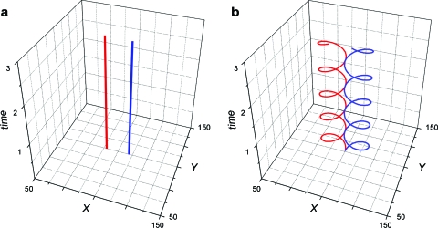
Not using the center of rotation to identify spiral wave tip dynamics can give rise to errors in the identification of the number and lifetime of spiral waves when multiple waves are present, as shown in Fig. 7. An episode of fibrillation as recorded from the heart surface can be represented by the number, location, and chirality of spiral waves at each instant in time.13 We illustrate the tip trajectories of a hypothetical stable figure-of-eight pair of spiral waves in Fig. 7 [in panel (a), the tip is identified as the center of rotation and thus the location of each spiral wave is stationary, while in panel (b), the tip is identified using traditional methods and each trajectory exhibits a cycloid pattern]. Since the identification of phase singularities [see Eq. 3] involves a spatial line integral, the exact line integral determines the lower limit (spatial resolution) on the localization of spiral wave tips. For example, if at a given instant both spiral wave tips are within the line integral of Eq. 3, then no phase singularities will be detected instead of two (one clockwise and one counterclockwise)! This will result in the erroneous inference that there is continuous birth and termination of two counter-rotating spiral waves instead of a continuous pair of stable counter-rotating spiral waves. Using the center of rotation to identify spiral wave tips will result in the correct interpretation.
Figure 7.
Analytically derived spatiotemporal spiral wave tip trajectories for stable figure-of-eight reentry. Position of spiral wave tip for clockwise (counterclockwise) rotating spiral is shown in blue (red). (a) The tip location at each instant of time for each spiral wave identified as the center of rotation, i.e., (x,y) site was (90,100) for counterclockwise and (110,100) for clockwise waves. (b) The tip locations identified using traditional methods which contain a rotational component, i.e., (x,y) site was (90+10* cos(ωs*t), 100+10* sin(ωs*t)) for counterclockwise and (110−10* cos(ωs*t), 100+10* sin(ωs*t)) for clockwise waves. See text for discussion.
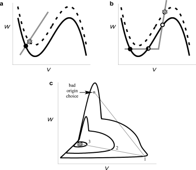
The state space representation of phase (θ) depends on the choice of origin as previously stated. It should be appreciated that is, in general, not equal to a fixed point in the space-clamped 0-D situation because the Laplacian term in Eq. 1 is nonzero. In fact, can be much different than the steady state homogenous solution because of the topology of state space, as shown in Figs. 8a, 8b. Trajectories in state space will always be closed curves for stable spiral waves; those near will be elliptical, and those away from the center will be nonelliptical. As shown in Fig. 8c the shape of all state space trajectories will influence the effect of nonideal origin choice and the ability to represent θ.
Figure 8.
State space dynamics. [(a) and (b)] Example nullclines for two-state variable systems. The fast variable nullcline (black) corresponds to dV∕dt=0 and the slow variable nullcline (gray) corresponds to dW∕dt=0. When the Laplacian term is zero (e.g., spatially homogenous state variable patterns) the fixed points of the system correspond to the intersection of the nullclines. For example, in excitable systems, there is a stable solution to the PDE [Eq. 4] that represents all sites at a “quiescent” state that corresponds to a stable fixed point (depicted as closed circles). Depending on the shape of the slow variable nullcline, there may be additional fixed points. For example, (b) depicts three intersections of the nullclines including a marginally stable fixed point (half-filled circle) and an unstable fixed point (open circle). The dashed lines indicate the effect of adding a constant value to the fast variable equation which corresponds to the dynamics at . This addition causes a vertical shift in the fast variable nullcline and the result is depicted as a dashed line. This shift may act to slightly perturb the quiescent solution as in (a) or may act to fundamentally change the system fixed points as in (b), where the shift results in the elimination of two fixed points. (c) The “bad” choice of origin illustrates nonunique θ representation as indicated by the three intersection points of the outermost trajectory by the gray line originating at the origin.
In many experimental situations, at least two limitations will preclude the use of our methodology. First, the underlying PDE corresponding to the experimental system is rarely known. Second, often the spatiotemporal dynamics of only one variable is measured. This latter problem may be overcome by using a “reconstructed state space,” V(t) and V(t+τ), in lieu of the actual state space in which case the origin is (V*,V*).13, 36 Obviously, Eq. 2 incorporates only two-state space variables, therefore systems with more than two variables may pose unique problems for our methodology. We have previously shown that the state space phase method accurately tracks linear motion in an eight-dimensional state space cardiac model.37 However, we wish to emphasize that even cardiac fibrillation, which is a very complex spatiotemporal phenomenon involving hundreds of variables, is amenable to state space phase analysis using two reconstructed state variables.13, 22 Furthermore, V* can be estimated as the measured value of the observed variable at the center of rotation of a spiral wave (ideally, a spiral wave rotating for multiple beats without meander). In practice the error in localizing spiral wave tips (i.e., phase singularities) will depend on the difference of origin choice from and the gradient of the fast variable near the center of rotation such that this localization error will be approximately .
We conclude that the flower gardens published in the literature tell us more about an arbitrary parameter (i.e., the choice of origin or isocontour) than the underlying spiral wave dynamics. We provide a method to analyze the dynamics of a system orbiting around its “natural” origin rather than around a fixed arbitrary one.
ACKNOWLEDGMENTS
We would like to thank Michael Cross for valuable discussions and comments on the manuscript. This work was supported by the National Institutes of Health (Grant Nos. R01-HL63267 to R.A.G. and R01-HL58241 to J.P.W.) and the National Science Foundation (CAREER Award to R.A.G.).
References
- Goldbeter A., Nature (London) 253, 540 (1975). 10.1038/253540a0 [DOI] [PubMed] [Google Scholar]
- Winfree A. T., The Geometry of Biological Time (Springer-Verlag, Berlin, 1980), Vol. XIII, p. 530. [Google Scholar]
- Lechleiter J., Girard S., Peralta E., and Clapham D., Science 252, 123 (1991). 10.1126/science.2011747 [DOI] [PubMed] [Google Scholar]
- Steinbock O., Zykov V., and Muller S. C., Nature (London) 366, 322 (1993). 10.1038/366322a0 [DOI] [Google Scholar]
- Li G., Ouyang Q., Petrov V., and Swinney H. L., Phys. Rev. Lett. 77, 2105 (1996). 10.1103/PhysRevLett.77.2105 [DOI] [PubMed] [Google Scholar]
- Vinson M., Mironov S., Mulvey S., and Pertsov A., Nature (London) 386, 477 (1997). 10.1038/386477a0 [DOI] [PubMed] [Google Scholar]
- Bazhenov M., Timofeev I., Steriade M., and Sejnowski T. J., Nat. Neurosci. 2, 168 (1999). 10.1038/5729 [DOI] [PubMed] [Google Scholar]
- Zykov V. S., Biofizika 25, 906 (1986). [Google Scholar]
- Winfree A. T., Chaos 1, 303 (1991). 10.1063/1.165844 [DOI] [PubMed] [Google Scholar]
- Beaumont J., Davidenko N., Davidenko J., and Jalife J., Biophys. J. 75, 1 (1998). 10.1016/S0006-3495(98)77490-9 [DOI] [PMC free article] [PubMed] [Google Scholar]
- Qu Z., Weiss J. N., and Garfinkel A., Am. J. Physiol. 276, H269 (1999). [DOI] [PubMed] [Google Scholar]
- Otani N. F., Chaos 12, 829 (2002). 10.1063/1.1503921 [DOI] [PubMed] [Google Scholar]
- Gray R. A., Pertsov A. M., and Jalife J., Nature (London) 392, 75 (1998). 10.1038/32164 [DOI] [PubMed] [Google Scholar]
- Copernicus N., De Revolutionibus Orbium Caelestium, edited by Duncan T. B. A. M. (Newton Abbot, New York, 1976), p. 1543. [Google Scholar]
- Winfree A. T., When Time Breaks Down: The Three-Dimensional Dynamics of Electrochemical Waves and Cardiac Arrhythmias (Princeton University Press, Princeton, NJ, 1987), Vol. XIV, p. 339. [Google Scholar]
- Huang X., Troy W. C., Yang Q., Ma H., Laing C. R., Schiff S. J., and Wu J. -Y., J. Neurosci. 24, 9897 (2004). 10.1523/JNEUROSCI.2705-04.2004 [DOI] [PMC free article] [PubMed] [Google Scholar]
- Clayton R. H. and Holden A. V., IEEE Trans. Biomed. Eng. 51, 28 (2004). 10.1109/TBME.2003.820356 [DOI] [PubMed] [Google Scholar]
- Panfilov A. V., Heart Rhythm 3, 862 (2006). 10.1016/j.hrthm.2005.12.022 [DOI] [PubMed] [Google Scholar]
- Gray R. A., Jalife J., Panfilov A. V., Baxter W. T., Cabo C., Davidenko J. M., Pertsov A. M., Science 270, 1222 (1995). 10.1126/science.270.5239.1222 [DOI] [PubMed] [Google Scholar]
- Gray R. A., Jalife J., Panfilov A., Baxter W. T., Cabo C., Davidenko J. M., and Pertsov A. M., Circulation 91, 2454 (1995). [DOI] [PubMed] [Google Scholar]
- Bray M. A. and Wikswo J. P., Phys. Rev. Lett. 90, 238303 (2003). 10.1103/PhysRevLett.90.238303 [DOI] [PubMed] [Google Scholar]
- Gray R. A. and Chattipakorn N., Proc. Natl. Acad. Sci. U.S.A. 102, 4672 (2005). 10.1073/pnas.0407860102 [DOI] [PMC free article] [PubMed] [Google Scholar]
- Clayton R. H., Zhuchkova E. A., and Panfilov A. V., Prog. Biophys. Mol. Biol. 90, 378 (2006). 10.1016/j.pbiomolbio.2005.06.011 [DOI] [PubMed] [Google Scholar]
- Fast V. G. and Pertsov A. M., Biofizika 35, 478 (1990). [PubMed] [Google Scholar]
- Fenton F. and Karma A., Chaos 8, 20 (1998). 10.1063/1.166311 [DOI] [PubMed] [Google Scholar]
- Mandapati R. et al. , Circulation 98, 1688 (1998). [DOI] [PubMed] [Google Scholar]
- Bray M. A., Lin S. -F., Aliev R. R., Roth B. J., and J. P.Wikswo, Jr., J. Cardiovasc. Electrophysiol. 12, 716 (2001). 10.1046/j.1540-8167.2001.00716.x [DOI] [PubMed] [Google Scholar]
- Puwal S., Roth B. J., and Kruk S., IMA J. Math. Appl. Med. Biol. 22, 335 (2005). 10.1093/imammb/dqi013 [DOI] [PubMed] [Google Scholar]
- Liu Y. B., Peter A., Lamp S. T., Weiss J. N., Chen P. -S., and Lin S. -F., J. Cardiovasc. Electrophysiol. 14, 1103 (2003). 10.1046/j.1540-8167.2003.03218.x [DOI] [PubMed] [Google Scholar]
- Iyer A. N. and Gray R. A., Ann. Biomed. Eng. 29, 47 (2001). 10.1114/1.1335538 [DOI] [PubMed] [Google Scholar]
- Fenton F. H., Cherry E. M., Hastings H. M., and Evans S. J., Chaos 12, 852 (2002). 10.1063/1.1504242 [DOI] [PubMed] [Google Scholar]
- Davidenko J. M., Pertsov A. V., Salomonsz R., Baxter W., and Jalife J., Nature (London) 355, 349 (1992). 10.1038/355349a0 [DOI] [PubMed] [Google Scholar]
- Barkley D., Phys. Rev. Lett. 68, 2090 (1992). 10.1103/PhysRevLett.68.2090 [DOI] [PubMed] [Google Scholar]
- Barkley D., Kness M., and Tuckerman L. S., Phys. Rev. A 42, 2489 (1990). 10.1103/PhysRevA.42.2489 [DOI] [PubMed] [Google Scholar]
- Biktashev V. N. and Holden A. V., Proc. R. Soc. London, Ser. B 263, 1373 (1996). 10.1098/rspb.1996.0201 [DOI] [Google Scholar]
- Takens F., in Dynamical Systems and Turbulence, edited by Rand D. A. and Young L. S. (Springer-Verlag, Berlin, 1981), pp. 366–381. [Google Scholar]
- Iyer A. and Gray R. A., Pacing Clin. Electrophysiol. 24, 692 (2001). [Google Scholar]


