Abstract
Split RF coils offer improved patient access by eliminating the need for the coil to be slid over the region of interest. For unshielded birdcage coils, the presence of end ring currents necessitates a direct electrical connection between two halves of the coil. For high-field (>3T) shielded birdcage coils, both the shield and the coil must be split and reliably connected electrically. This problem can be circumvented by the use of split TEM volume coils. Since the elements of a TEM coil are coupled inductively, no direct electrical connection between the halves is necessary. In this work we demonstrate that the effects of splitting the shield for head and knee TEMs can be compensated for, and performance retained. For the knee, the improved access allowed the coil diameter to be reduced, enhancing the sensitivity by 15–20 %.
Keywords: TEM, RF knee coil, RF head coil, RF split volume coil, high field MRI/MRS
INTRODUCTION
Conventional high-field RF coils for the human head and limb are typically formed from rigid cylinders. The use of this design requires that either the coil be slid over the subject or alternately the subject slides into the coil. For patients with impaired or limited mobility this can make positioning difficult. Additionally, when receive-only arrays are used within the transmission coil, the ability to both place and visualize the location of the array is limited. These limitations can be overcome using a split “two-piece” coil. Split unshielded birdcage coils have been described for field strengths up to 3 T (1). Due to the presence of end ring RF currents, split birdcage coils require a continuous electrical connection between two halves of the coil (1). Additionally, most high-field (> 3 T) head-sized RF coils use a shield surrounding the entire coil to decrease radiation losses (2). For shielded RF coils, both the birdcage coil and the shield must be separated and reliably reconnected electrically during each use, which complicates both the fabrication and utilization. Therefore, to our best knowledge, the construction of high-field (> 4 T) split shielded birdcage coils, has not been described in the literature. However, transverse electromagnetic (TEM) RF coils (3), due to use of through-space inductive coupling between resonant elements (3), can circumvent this limitation, since the two halves of the coil do not require electrical continuity. Also the TEM design has been demonstrated to have certain advantages over the birdcage design at higher fields (> 3T) (4–7). The TEM design has been successfully applied for head and body coils (3,4,8,9) up to 7T. The TEM coil inductance depends on the ratio of the RF shield diameter to the inside diameter of the coil (3) rather than on the absolute value of the coil diameter such as in the BC coils. The latter does not take into account the dependence of the BC inductance on the distance to a shield, which is substantially weaker than its dependence on the coil radius. Thus, it is much easier to scale the TEM coil size up while keeping the inductance low. This design decreases radiation losses and improves current distributions (no end ring current). Quantitative comparisons of the TEM and birdcage designs at frequencies greater than 120 MHz have demonstrated advantages of the TEM over the most commonly used design of the birdcage coil (straight cylindrical shield, flat rungs) (4–7). For example, Vaughan at al (4) reported that a quadrature TEM head coil was almost 20% more effective than a similar in size birdcage coil at 4 T.
Previous works by Vaughan et al (10–12) have described split TEM coils. However, these reports did not provide technical details of the design and construction or experimental performance data (10–12) describing how the splits in the TEM shield modify the distribution of RF currents in the resonant elements and affect the coil performance. In this work we report the detailed design, construction and performance analysis of split 4 T TEM volume coils for the human knee and head. We also provide a comparison of the performance of the split TEM coils with their corresponding one-piece counterparts.
METHODS
Coil design and evaluation procedures
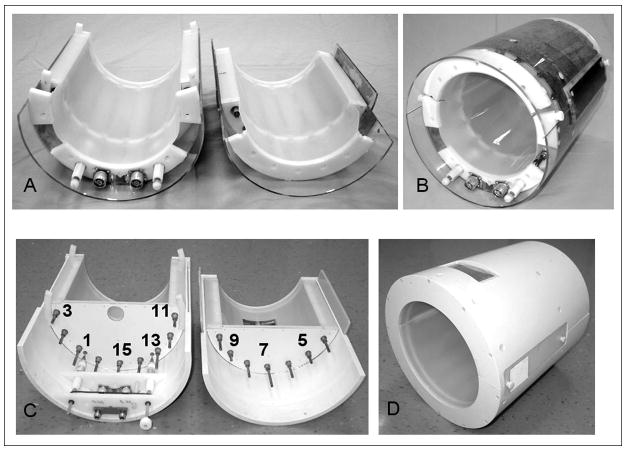
16-element TEM open-end coils for knee imaging (Figs. 1A,B) and closed-end head (Figs. 1C,D) quadrature coils were built using coaxial resonant elements with Teflon inserts as described by Vaughan et al (3). Copper tubes with 12.5 cm OD (wall thickness 0.6 mm) and 6.4 cm OD were utilized to construct the outer shell and central conductor of the TEM elements, respectively. The open-end split TEM coil for the knee was 20 cm in length with an RF shield diameter of 24.8 cm and an element ID (diameter measured at the element centers) of 21 cm. The coil had an inner diameter clearance of 18.8 cm. The head coil had one end closed and shielded for improved homogeneity of the RF field (3). The head coil was 21 cm in length with an RF shield diameter of 33.2 cm, an element ID of 27.5 cm and an inner diameter clearance of 25.3 cm. The outer shell of the open-end split coil was constructed using a 25.4 cm OD acrylic cylinder with a 3.2 mm wall thickness. The split head coil was built from a 35.6 cm OD PVC pipe with 1.2 cm walls. The shield for both coils was constructed from a 50 μm polyamide film with a 5 μm copper layer laminated on top of it (Gould Electronics, Eastlake, Ohio). The thickness of the copper is approximately equal to the skin depth at 170 MHz (1H frequency at 4 T). This allowed us to preserve a high unloaded Q-factor for the TEM resonator while suppressing gradient eddy currents (3,4,8,9). To provide a view for patients, the top portion of the head coils had a window opening (11 × 5.5 cm) covered by a copper mesh, which was electrically connected to the shield at the edges (Fig 1D). Comparison of the TEM coils with and without window cut revealed no change in the coil performance. Both TEM coils were driven in quadrature using capacitive matching and a two-port drive (Fig. 1) with the driven elements located at the bottom of the coils. The coils were driven in quadrature using high power 90° hybrids (MAC Technology, Klamath Falls, OR). Adjustable matching of the coils within the magnet was provided by use of high voltage variable capacitors (Jennings Technology, San Jose, CA) connected to the driven elements. Although there is no provision for variable tuning within the magnet the variation in resonance frequency from head to head (<200 kHz) was mush smaller than resonance line width of the loaded coil (~3 MHz). Thus subject dependent changes in resonance frequency did not significantly alter performance. The subject dependent change in resonance frequency for the split TEM knee coil was also substantially smaller than the coil’s resonance line width (~2.5 MHz). The shift in resonance frequency was less than 0.4 MHz when the coil was positioned over the calf, knee and thigh of the same individual. The power required to produce 90° pulse in the calf and the thigh differed by 5 dB. The coils were split into two parts (9 elements in the lower portion and 7 in the top portion) with no electrical connection between them. In spite of a fairly small gap (1–2 mm) between the shields, the coupling between the two elements adjacent to the split was reduced by about 40 % in comparison to the coupling between adjacent elements located near the top or bottom of the coil. The coupling was evaluated by measuring the frequency split between two resonance modes with all other elements removed from the resonator (13). The coupling was restored (75 % of the value measured for two elements located at the bottom (or top)) by overlapping the split between the two halves of the TEM coil with an electrically insulated piece of shield, (Fig. 1). These side shields were constructed from the same type of foil as the major shield. The side shields were insulated and positioned symmetrically near both splits at about 3 mm from the major shield (distance determined by plastic insulation). They measured 5 cm in width and 22 in length. The ratio of unloaded to loaded Q-factors, QU/QL, was 700/60 and 740/70 for head and knee coils, respectively. These measurements were performed using a spherical 2.0 L (16 cm dia., 50 mM NaCl) phantom for the head coil and a cylindrical 2.0 L (12 cm dia., 50 mM NaCl) phantom for the knee coil. The unloaded Q-factors of both TEM coils were unaffected by the splits. The Q-factors were measured from frequency dependence of the S11 reflection coefficient of the matched coils, using the ratio of the resonance frequency to the resonance width at the −3 dB level. Splitting of the shield also did not significantly affect the separation between the TEM modes, which measured 8–10 MHz for the split knee coil and 10–12 MHz for the split head coil.
Figure 1.
Assembled and disassembled pictures of A), B) knee and C), D) head split TEM volume coils.
Each coil was initially adjusted to obtain sufficient isolation (better than −12 dB) between the modes mostly by changing impedance of top and bottom elements and then tuned using a procedure developed in our lab (14). After tuning, the isolation, S12, between linear modes of each quadrature coil was better than −20 dB on the phantom and a human head. The tuning was then verified in the magnet. Knee images were obtained on a 4 T Varian Inova System (Varian Associates, Inc., Palo Alto, CA) using T1-weighted fast spin echo sequence with TR = 1.2 s, TE = 26.4 ms, echo train length = 16, 18 slices, slice thickness = 3 mm, gap = 3 mm, and in-plane resolution = 0.625 mm (matrix size 512 × 256, FOV = 320 × 160 mm for sagittal and coronal images; matrix size 256 × 256, FOV 160 × 160 for axial images). The data were acquired with a single average.
Brain images were also acquired on a 4 Tesla Varian Inova system. To test the coil performance, gradient echo images of the phantom and a human head were collected using 128 × 128 and 256 × 256 resolution respectively, 1.5 mm slice thickness, 20 × 20 cm field of view (FOV), TE = 50 ms, TR = 400 ms, flip angle = 30°. To provide anatomical contrast, a T1-weighted inversion recovery gradient echo sequence was used with TR = 2500 ms, TIR = 900 ms, a 90° excitation pulse, a slice thickness of 1.5 mm with 128 × 128 resolution over an FOV of 19.2 × 19.2 cm. Echo planar images (EPI) brain images were acquired using a T2*-weighted gradient-echo EPI pulse sequence (TR/TE = 5000/25 ms, FOV = 256 × 256 cm, matrix 64 × 64 pixels, slice-thickness = 4 mm, flip angle = 90°) without interleaving. All brain images were acquired with a single average.
The performance of the split coils was compared to their one-piece counterparts. The one-piece open-end TEM coil (15) used for knee imaging was larger so as to provide easy access of the leg and had a shield diameter of 33 cm and element ID of 27.5 cm. Performance of this coil was compared to the split TEM knee coil. The non-split closed-end head coil had exactly the same size and geometry as the spilt head coil. Again a spherical 2.0 L (16 cm dia., 50 mM NaCl) phantom was used for the head coil and a cylindrical 2.0 L (12 cm dia., 50 mM NaCl) phantom for the knee coil. The efficiency of the coils was assessed by determination of the B1 field required to produce a 90° rotation using a slice selective excitation pulse in a transverse slice in the center of the RF coil longitudinally in the head, knee and tissue mimicking phantoms. To eliminate the effects of shaping the RF pulse, the B1 value in kHz (or μT) per 1 kW of power was calculated based on the equivalent maximum amplitude square pulse duration. The homogeneity of the coils was measured by acquiring B1 maps of the transmit field using the procedure described by Pan et al (16) using 64 × 64 resolution and 3 mm thickness.
Effect of splitting the coil and rationale for the adjustment procedure
To better understand the effect of splitting the coil, we can view the N-element TEM volume coil as a multi-mode structure supporting N modes resonating at different frequencies constrained by the boundary condition that the total phase shift is 2πn (0 ≤ n ≤ N/2) per complete revolution about the coil (3). The lowest and the highest modes are two singlets (n = 0 and n = N/2) with the rest of the modes being a set of degenerate doublets (3). The lowest frequency doublet (n = 1) provides degenerate modes with the most homogeneous RF magnetic field distribution, which can be driven in quadrature to produce a circularly polarized field. Splitting the shield between the elements reduces the inductive coupling between the elements adjacent to the splits, thereby spoiling the isolation between these two linear modes by mixing them with other modes. These modes can also be considered as a set of standing waves produced by interference of two waves propagating from element to element in opposite radial directions similarly as in a transmission line. Viewing the set of TEM elements as a piece of a transmission line can help in analyzing the change in the RF current distribution. Reducing coupling between the elements adjacent to the splits results in reflection of the propagating waves at the discontinuities created by the splits. Reflection from both splits produces changes in the current in each TEM element with the distribution of the changes having a half-wave length profile over both halves of the split coil. Since the decrease of the coupling between the elements adjacent to the splits is equivalent to a decrease of the impedance viewed from the perspective of the propagating wave, this results in a decrease of the voltage and an increase of the current in the standing wave in the elements adjacent to the splits. Thus, the resulting distribution of the current changes will have a half-wave length shape in both portions of the split coil with the maximal increase in current in the elements adjacent to the splits and no change in the elements located in the middle between the two splits (top and bottom elements).
To simplify the tuning of a multi-mode coil, the elements, which affect only one of the modes without changing the others, are used. Thus, to restore the isolation between the linear modes of the TEM, the elements 7 (top) and 15 (bottom) (Fig. 1C) can be utilized. These elements strongly affect the isolation between the modes of the closed TEM due to their location at 45° relative to the driven elements (17) and as discussed above do not affect the standing waves due to reflections at the splits. The symmetry of the current distribution may be restored by increasing the impedance of the elements located near the splits (elements 3,4,10,11), thus, decreasing their current. Intuitively one might try to compensate for the decrease in coupling between two elements adjacent to the split by increasing current in these elements. However, this neglects the interaction with other elements of the TEM and does not resolve the problem.
Tuning method
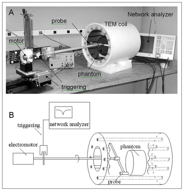
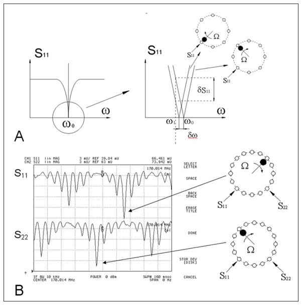
Figure 2 shows a picture and a block-diagram of the tuning method developed in our lab previously (14) for tuning TEM volume coils. In this method rotation of a small magnetic or a dielectric probe in close proximity to the TEM elements produces a shift of the resonance frequency proportional to the square of the amplitude of the RF current flowing in the corresponding element (Fig. 3A). By measuring changes of the S11 reflection coefficient, caused by the modulation of the resonance frequency, the distribution of the current in all of the TEM elements can be visualized simultaneously on a network analyzer as shown in Fig. 3. Probes were mounted on the end of G10 plastic rod and rotated using a small DC motor as shown in Fig. 2. The angular position of the probe was determined using a small infrared (IR) source/receiver and a disk mounted to the G10 rod (Fig. 2). The TTL signal, generated by IR triggering system was used to start the network analyzer. To observe the S11 modulation, which reflects the current distribution in the TEM elements (Fig. 3B), the network analyzer was externally triggered in the linear amplitude mode with the frequency sweep turned off. This method allows easy and quick bench measurements of the current distribution in the resonant elements for each linear mode of the volume coil. By adjusting the sinusoidal symmetry of the current distribution (18) the optimal homogeneity of the B1 field can be achieved (14). The currents in resonant coaxial elements are adjusted by varying their impedance, which is achieved by changing the extent of the overlap between the central rod and its shell (a change in capacitance).
Figure 2.
A) Picture and B) block-diagram of the TEM coil tuning method. A ferrite probe rotated in close proximity to TEM elements to produce a shift of the resonance frequency and modulate S11. To visualize the modulation of S11, which reflects the current distribution in the TEM elements, the network analyzer was used in the linear amplitude mode with the frequency sweep turned off. The network analyzer was externally triggered from the rotation of the probe.
Figure 3.
A) Frequency dependence of the S11 reflection coefficient. The bottom linear part of the dependence is magnified on the right side of the figure. Two curves, measured at one of the driving ports correspond to probe positions near TEM elements with maximum (bottom element) and zero RF current (top element). The network analyzer is used in cw mode at a frequency of ω1. B) Distribution of the current in both linear channels of the TEM volume coil as observed on the network analyzer. The tuning method allows visualization of the two distributions of current for both linear modes simultaneously. The right side of the figure correlates the probe position to a corresponding peak in the current distribution.
RESULTS AND DISCUSSION
As predicted, splitting the shield and the consequent reduction of the coupling between the elements adjacent to the splits substantially decreased isolation between two linear modes of the TEM coil, thus, compromising the performance of the coil. The reduction in mutual inductive coupling between adjacent elements from the introduction of a very small split in the shield suggests that the TEM structure supports some residual RF currents flowing in the shield in radial direction near the ends of the coil perpendicular to the coil axis. This is similar to end ring currents in birdcage coils. Introduction of a small split (much smaller than a wavelength) in a shield of a resonator parallel to RF currents should not substantially modify the RF field distribution or cause mode coupling. However, introducing a split perpendicular to current flow will have a substantial effect (19).
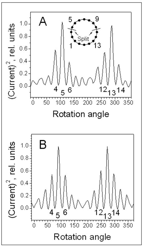
To decouple the modes and to tune the TEM volume coil we used a procedure described above. Figure 4A shows the distribution of current in the split knee TEM coil elements measured for one of the linear modes with the coil driven at element 13. For convenience the plot observed on the screen of a network analyzer (Fig. 3) was flipped vertically and normalized. The measurement was performed after the coil was adjusted to restore the isolation between the two modes. Since the method detects the square of the amplitude of current and is not sensitive to the phase (14) both halves of the sinusoidal distribution have the same sign. As seen from the figure, the current distribution is not symmetric. Specifically, the current is increased in the elements adjacent to the splits (elements number 4, 11, 12) as compared to elements distant from the splits (elements number 6, 14, 15). Figure 4B shows the symmetric current distribution measured for one of the linear modes of the one-piece TEM volume coil. To restore the symmetry of the current distribution of the split TEM we decreased the current in the elements adjacent to the splits as well as their immediate neighbors (elements 2, 5 and 9, 12). In practice, it was not possible to completely restore the symmetry without degrading the isolation between two linear modes. The isolation between the modes was adjusted primarily by decreasing the current in elements 7 (top) and 15 (bottom). Adjusting these two elements was the most effective way to restore the mode isolation as compared to tuning the other elements. The analogous distribution was also measured for the other linear mode of the TEM coil with the current increased in elements adjacent to the splits. The distribution of current flowing in TEM elements was also measured for the split head coil and produced a very similar pattern to shown in Fig. 4A.
Figure 4.
A) The distribution of RF currents in elements of the quadrature TEM split knee volume coil measured for one of the linear modes after the coil has been tuned and adjusted. B) The distribution of current in elements of continuous non-split TEM coil measured similarly as in A).
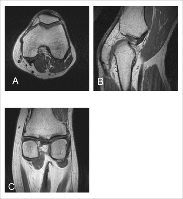
The residual asymmetry of the current distribution didn’t substantially affect the quality of the images or the overall coil performance. Figure 5 demonstrates transverse, sagittal, and coronal T1-weighted spin-echo images of a human knee obtained using the split TEM knee coil. The split TEM knee coil was about 15–20% more efficient than the larger one-piece open-end TEM coil. We obtained a similar result for 2.0 L cylindrical leg-mimicking phantom. This increase in SNR of the split TEM can be attributed to a decrease in coil volume (due to a change in the coil diameter) as well as minimizing the extension of the B1 field from the wider coil’s openings. The small decrease in signal at the very top of the coil is most likely due to the residual asymmetry of the current distribution. The split TEM knee coil generated a circular polarized RF magnetic field B1 of 1.43 kHz (or 33.6 μT) in amplitude in the central transverse slice of an average size human knee using 1 kW RF. Since the size of a human knee can vary we also performed this measurement using 2.0 L cylindrical phantom (12 cm dia., 50 mM NaCl) and obtained a B1 of 2.0 kHz (or 47 μT) per 1 kW. To quantitatively evaluate the coil sensitivity we attempted to measure B1 map of the transmit field (16). Unfortunately, it was difficult to map the transmit B1 field due to the minimal signal arising from bone tissue. Therefore, the analysis of the effect of the changes in the distribution of current on the homogeneity of the B1 field was performed using the head coil.
Figure 5.
A) Transverse, B) sagital, and C) coronal human knee spin-echo images obtained using split TEM volume coil.
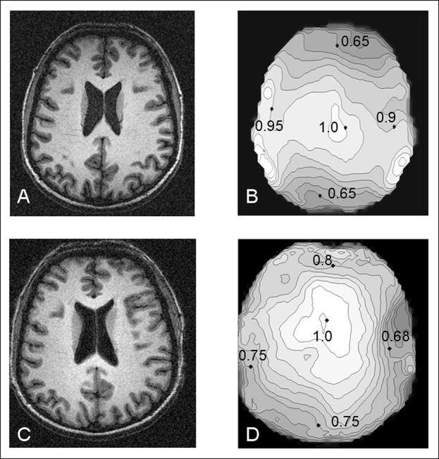
Figure 6 shows head images and B1 field maps obtained with the split TEM head coil and the one-piece TEM coil of the same size. All of the images and the B1 maps demonstrate a very characteristic pattern of increased magnitude in the center of the brain as compared to the periphery due to standing waves formed in dielectric media (8,20,21). The magnitude of the B1 field measured at the top and the bottom of the split coil is ~10–15 % lower in comparison to the analogous positions for the one-piece coil. Conversely, the B1 field produced at the left and right sides of the split-coil was ~20–25% greater than B1 field from the same locations for the one-piece coil. These in vivo measurements are in good agreement with the differences in current distribution between the two coils obtained by our bench measurements. The symmetric current distribution of the one-piece coil (Fig. 4B) produced a symmetric B1 map pattern (Fig 6D). In contrast, the higher current near the splits (Fig. 4A) in the split-coil enhances the B1 field at the left and the right sides of the volume coil (Fig. 6B). It is noteworthy, that the asymmetry in the B1 distribution of the split coil (top/bottom vs. left/right) is due more to enhancement in B1 field at the left and the right sides of the head than a decrease in B1 field at the top and bottom of the coil. The alteration in B1 distribution, however, did not substantially degrade the quality of the images shown in Figs. 6A and C.
Figure 6.
Gradient echo human brain images and B1 maps of the corresponding slices obtained using A), B) split TEM volume coil and C), D) continuous non-split coil of the same size.
The split TEM head coil generated a circular polarized RF magnetic field B1 of 1.1 kHz (or 25.8 μT) in amplitude in the central transverse slice of a human head using 1 kW RF. This is similar to or better than previously reported for a non-split quadrature TEM head volume coil of similar size (diameter at the element centers - 27 cm, length 21 cm) that provided the equivalent of a 255 μs 90° square pulse in the central transverse slice of the head using 1 kW RF power (4). This corresponds to a B1 field amplitude of 0.98 kHz (or 23 μT). We also evaluated the effectiveness of the quadrature TEM head coil in producing circular polarized RF magnetic field using a B1 mapping method (16). The ratio of the B1+ and B1− components of the circular polarized magnetic field rotating clockwise and counter clockwise, respectively, averaged over the entire human head, measured better than 10 dB. This indicates that the average loss of the amplitude of the transmit B1+ field due to the contribution of the B1− component was less than 5 %. Finally, the average B1 field (measured over the entire slice) as well as power required to produce a 90° pulse in the transaxial slice at the center of the coil were approximately the same for both split and non-split TEM head coils within the error of the experiment (± 1 dB). In comparison, a commercially available 3T split head-sized birdcage coil (USA Instruments, Aurora, Ohio) generated a B1 field of 0.82 kHz (19.3 μT) per 1 kW of power using standard Siemens head phantom. Figure 7 presents EPI data obtained using split head coil. No evidence of substantial eddy current artifacts was observed in the images.
Figure 7.
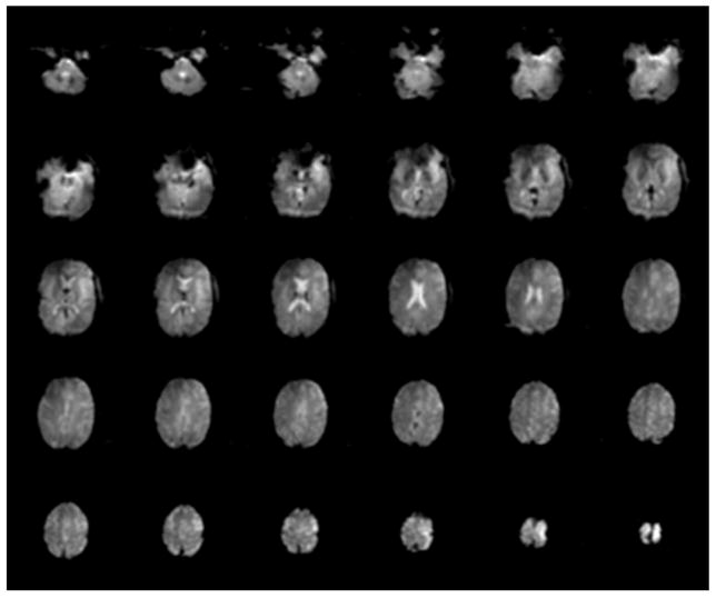
EPI images of a human brain obtained using TEM split head coil.
CONCLUSIONS
Introduction of a relatively small split (1–2 mm) along the longitudinal axis of the outer conductor (shield) of a TEM coil substantially changed the coupling between the elements adjacent to the split and increased the coupling between the two linear modes of the TEM coil. This suggests that the TEM structure supports some residual radial RF currents flowing in the shield perpendicular to the coil axis. However, as demonstrated, this effect can be compensated for by adjusting the impedances of the coil elements. Using this approach, we have developed split TEM volume coils for the knee and head. For the head coil, no significant difference in overall performance was detected in comparison to a one-piece coil of the same size. For the knee, splitting the coil allowed the diameter to be reduced, thereby improving sensitivity as well as patient comfort and accessibility.
Acknowledgments
This work was supported by R01-EB00473, R21-EB005438. We also thank MR Instruments Inc. (Minneapolis, MN) for financial and technical support.
Footnotes
Publisher's Disclaimer: This is a PDF file of an unedited manuscript that has been accepted for publication. As a service to our customers we are providing this early version of the manuscript. The manuscript will undergo copyediting, typesetting, and review of the resulting proof before it is published in its final citable form. Please note that during the production process errors may be discovered which could affect the content, and all legal disclaimers that apply to the journal pertain.
References
- 1.Peterson DM, Carruthers CE, Wolverton BL, Meister K, Werner M, Duensing GR, Fitzsimmons JR. Application of a birdcage coil at 3 Tesla to imaging of the human knee using MRI. Magn Reson Med. 1999;42:215–221. doi: 10.1002/(sici)1522-2594(199908)42:2<215::aid-mrm1>3.0.co;2-8. [DOI] [PubMed] [Google Scholar]
- 2.Harpen MD. Irradiative loss of a bird cage resonator. Magn Reson Med. 1993;29:713–716. doi: 10.1002/mrm.1910290522. [DOI] [PubMed] [Google Scholar]
- 3.Vaughan JT, Hetherington HP, Otu JO, Pan JW, Pohost GM. High frequency volume coils for clinical NMR imaging and spectroscopy. Magn Reson Med. 1994;32:206–218. doi: 10.1002/mrm.1910320209. [DOI] [PubMed] [Google Scholar]
- 4.Vaughan JT, Garwood M, Collins CM, Liu W, DelaBarre L, Adriany G, Andersen GP, Merkle H, Goebel R, Smith MB, Ugurbil K. 7T vs. 4T: RF power, homogeneity, and signal-to-noise comparison in head images. Magn Reson Med. 2001;46:24–30. doi: 10.1002/mrm.1156. [DOI] [PubMed] [Google Scholar]
- 5.Vaughan JT, Adriany G, Garwood M, Yacoub T, Duong T, DelaBarre L, Andersen P, Ugurbil K. Detunable Transverse Electromagnetic (TEM) volume coil for high field NMR. Magn Reson Med. 2002;47:990–1000. doi: 10.1002/mrm.10141. [DOI] [PubMed] [Google Scholar]
- 6.Vaughan JT, Snyder C, DelaBarre L, Bolinger L, Tian J, Andersen P, Strupp J, Adriany G, Ugurbil K. 7 T Body Imaging: first results. Proceedings of the 14th annual meeting of ISMRM; Seattle, Washington. 2006. p. 213. [Google Scholar]
- 7.Adriany G, Vaughan JT, Andersen P, Merkle H, Garwood M, Ugurbil K. Comparison between head volume coils at high fields. Proceedings of the 3d annual meeting of ISMRM; Nice, France. 1995. p. 971. [Google Scholar]
- 8.Vaughan JT. An RF volume coil comparison study: 1.5T to 9.4T. Proceedings of the 6th annual meeting of ISMRM; Sydney, Australia. 1998. p. 646. [Google Scholar]
- 9.Tian J, Vaughan JT. Frequency limit and radiation resistance for volume coils. Proceedings of the 11th annual meeting of ISMRM; Toronto, Canada. 2003. p. 2354. [Google Scholar]
- 10.Vaughan JT, Adriany G, Ugurbil K. United States Patent 6,788,056. B2. 2004. Radio frequency magnetic field unit with aperture. [Google Scholar]
- 11.Vaughan JT, Garwood M, Ugurbil K. Volume coils for highest field MRI, Trans. 2001 Antenna and Propagation Society International Symposium. 2001;1:378–381. [Google Scholar]
- 12.Vaughan JT, Adriany G, Waks M, Watson M, Thompson T, Liu H, Berghoff G, Sundquist K, Ugurbil K. A patient friendly head coil for high field MRI. Proceedings of the 11th annual meeting of the ISMRM; Toronto, Canada. 2003. p. 718. [Google Scholar]
- 13.Tropp J. Mutual inductance in the bird-cage resonator. J Magn Reson. 1997;126:9–17. doi: 10.1006/jmre.1997.1149. [DOI] [PubMed] [Google Scholar]
- 14.Avdievich NI, Krymov VN, Hetherington HP. Modified perturbation method for transverse electromagnetic (TEM) coil tuning and evaluation. Magn Reson Med. 2003;50:13–18. doi: 10.1002/mrm.10539. [DOI] [PubMed] [Google Scholar]
- 15.Hwang JH, Pan JW, Heydari S, Hetherington HP, Stein DT. Regional differences in intramyocellular lipids in humans observed by in vivo 1H-MR spectroscopic imaging. J Appl Physiol. 2001;90(4):1267–1274. doi: 10.1152/jappl.2001.90.4.1267. [DOI] [PubMed] [Google Scholar]
- 16.Pan JW, Twieg DB, Hetherington HP. Quantitative spectroscopic imaging of the human brain. Magn Reson Med. 1998;40:363–369. doi: 10.1002/mrm.1910400305. [DOI] [PubMed] [Google Scholar]
- 17.Tropp J. The theory of an arbitrary perturbed bird-cage resonator, and a simple method for restoring it to full symmetry. J Magn Reson. 1991;95:235–243. [Google Scholar]
- 18.Hayes CE, Edelstein WA, Schenck JF, Mueller OM, Eash M. An efficient, highly homogeneous radiofrequency coil for whole-body imaging at 1.5 T. J Magn Reson. 1985;63:622–628. [Google Scholar]
- 19.Poole CPJ. Electron spin resonance: a comprehensive treatise on experimental techniques. New York: Wiley; 1983. [Google Scholar]
- 20.Glover GH, Hayes CE, Pelc NJ, Edelstein WA, Mueller OM, Hart HR, Hardy CJ, O’Donnell M, Barber WD. Comparison of linear and circular polarization for magnetic resonance imaging. J Magn Reson. 1985;64:255–270. [Google Scholar]
- 21.Collins CM, Liu W, Schreiber W, Yang QX, Smith MB. Central brightening due to constructive interference with, without, and despite dielectric resonance. J Magn Reson Imag. 2005;21:192–196. doi: 10.1002/jmri.20245. [DOI] [PubMed] [Google Scholar]


