Abstract
A goal of biomimetic chemistry is to use the hierarchical architecture inherent in biological systems to guide the synthesis of functional three dimensional structures. Viruses and other highly symmetrical protein cage architectures provide defined scaffolds to initiate hierarchical structure assembly. Here we demonstrate that a crosslinked branched polymer can be initiated and synthesized within the interior cavity of a protein cage architecture. Creating this polymer network allows for the spatial control of pendant reactive sites and dramatically increases the stability of the cage architecture. This material was generated by the sequential coupling of multifunctional monomers using click chemistry to create a branched crosslinked polymer network. Analysis of polymer growth by mass spectrometry demonstrated that the polymer was initiated at the interior surface of the cage at genetically introduced cysteine reactive sites. The polymer grew as expected to generation 2.5 where it was limited by the size constraints of the cavity. The polymer network was fully crosslinked across protein subunits that make up the cage and extended the thermal stability for the cage to at least 120°C. The introduced reactive centers were shown to be active and their number density increased with increasing generation. This synthetic approach provides a new avenue for creating defined polymer networks, spatially constrained by a biological template.
Introduction
Protein cages consist of a family of spherical nanoparticles composed of protein subunits.1 The protein subunits are arranged symmetrically in a shell that encloses an interior compartment. The family of protein cages includes viral capsids2 as well as a variety of non-viral multimeric protein architectures such as ferritins, Dps and heat shock proteins.3–6 Utilizing high resolution structural information and an appropriate genetic system a protein cage becomes a versatile molecular scaffold upon which multiple chemical and biological functionalities can be added in a spatially defined manner both chemically7–9 and genetically.10–11 Biomedical applications of protein cages include targeted delivery of agents for imaging and treatment of tumors and infections.10–11 The potential for large magnetic material payloads and the ideal rotational properties of protein cages make them extremely well suited for MRI (magnetic resonance imaging) contrast enhancement.12,13 Protein cages have been used as nanoscale reaction vessels for constrained synthesis of inorganic materials, including catalytic14–16, magnetic12,17–21 and semi-conductor materials22–24, and as single-enzyme nanoreactors.25 Since they can be assembled into higher order structures26–31 they contribute to the toolkit of nanoscale building blocks that can be incorporated into devices.
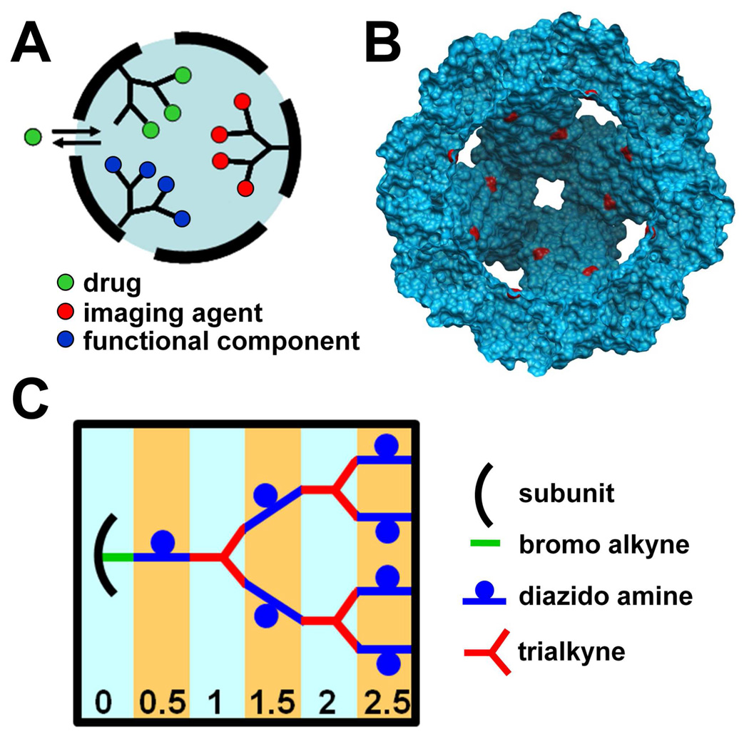
The interior cavity of protein cages serves the biological function of packaging organic polymers (DNA or RNA) in the case of viral protein cages or nucleating and encapsulating an inorganic polymer (Fe2O3) in the case of ferritins. An engineered approach for filling protein cages with a synthetic polymer incorporating functionalizable pendant groups would enhance their potential applications as targeted delivery vehicles and components of solid state devices (Figure 1A).32,33 We designed a strategy for filling a protein cage, Heat Shock Protein (Hsp) from Methanococcus jannaschii (Figure 1B), with a synthetic polymer. We chose to synthesize branched dendritic structures since they can take full advantage of the interior volume of the cage by completely filling the cavity with functional groups in an ordered, sequential fashion using a single site on each protein subunit to nucleate polymer growth (Figure 1C).
Figure 1.
Rationale and strategy for fabricating a hybrid protein cage/dendritic structure (A) cartoon of a protein cage filled with a branched polymer; addressable sites on the polymer can be used to load drugs, imaging agents or functional components of a solid state device into the interior compartment; polymeric crosslinks between protein cage subunits enhance cage stability; (B) A cutaway view of the HspG41C genetic construct showing cysteine residues (red) exposed to the interior cavity; (C) Scheme for sequential synthesis of the dendritic structure. Generation numbers are indicated at the bottom. Details of the chemistry are shown in Scheme 1.
Polymer growth was initiated from cysteine residues located on the interior surface of a genetic Hsp construct (G41C) (Figure 1B). Recombinant Hsp self-assembles in an E. coli expression system from 24 identical protein subunits forming a spherical container of 12 nm exterior diameter and 6.5 nm interior diameter34. The Hsp cage is relatively porous and robust making it a good model system for internal modification. The presence of eight 3 nm pores at the 3-fold and six 1.7 nm pores at the 4-fold axis allows free access of small molecules to the interior cavity35 and it is stable up to ~60 °C and in a pH range of 5–8.36
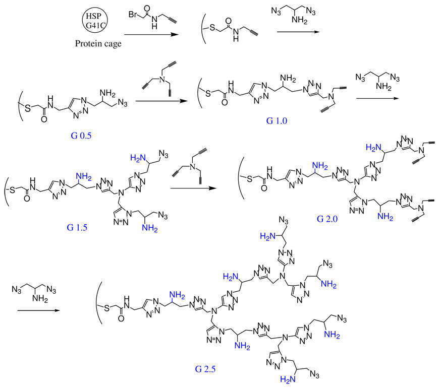
A click chemistry approach was used to synthesize polymers in the interior cavity of the HspG41C cages (Figure 1C and Scheme 1) since it provides a means to produce covalently linked branched polymers using aqueous phase chemistry compatible with modification of biopolymers. Click chemistry commonly employs the coupling of alkyne and azide functional groups through hetero [3+2] cycloaddition reactions mediated by a Cu(I) catalyst in the presence of a Cu binding ligand.37,38 Recently, click chemistry has been employed for adding peptides7, fluorophores7,38 and glycopolymers39 on the surface of capsids. Using this chemistry we incorporated free amines into the branched polymer as sites for internal functionalization (Figure 1C and Scheme 1). We demonstrate that these sites are addressable for covalent addition of functional molecules in the cavity and that the polymer stabilizes Hsp as it fills the interior and covalently crosslinks the protein subunits.
Scheme 1.
Synthetic scheme for the generation of G 0.5, G 1.0, G 1.5, 2.0 and 2.5 branched polymers within the HspG41C protein cage
Results and Discussion
Branched polymer synthesis strategy
A branched polymer was grown selectively in a stepwise fashion within the Hsp cage (Figure 1C and Scheme 1). The polymer was initiated by reaction of N-propargyl bromoacetamide with a genetically engineered cysteine, located on the interior of the cage-like architecture (Figure 1B). This alkyne derivative is referred to as G41C-alkyne (G41C-alk). The exposed alkyne was subsequently reacted with 2-azido-1-azidomethyl ethylamine via a Cu(I) catalyzed ‘click’ reaction to yield G 0.5. Exposed azide functional groups on G 0.5 were subsequently ‘clicked' with tripropargyl amine to generate a branched structure (G 1.0). Iterative stepwise reactions with 2-azido-1-azidomethyl-ethylamine and tripropargyl amine were then undertaken to produce generations G1.5, G2.0, G2.5 and the stepwise process was continued until no further reaction was observed.
Increases in mass associated with sequential addition to the dendritic structure
The increase in mass accompanying the stepwise polymer growth was characterized by mass spectrometry (MS). Two types of MS analyses were performed. Conventional liquid chromatography/electrospray mass spectrometry (LC/MS) was used to measure masses added to individual G41C protein cage subunits (16,498 Da). As the polymer was extended to higher generations (G 1.5 and higher) the individual subunits could no longer be detected due to internal polymer crosslinking. For these higher generations mass spectrometer parameters were tuned to detect the entire G41C protein cage (396 kDa) including the encapsulated polymer.
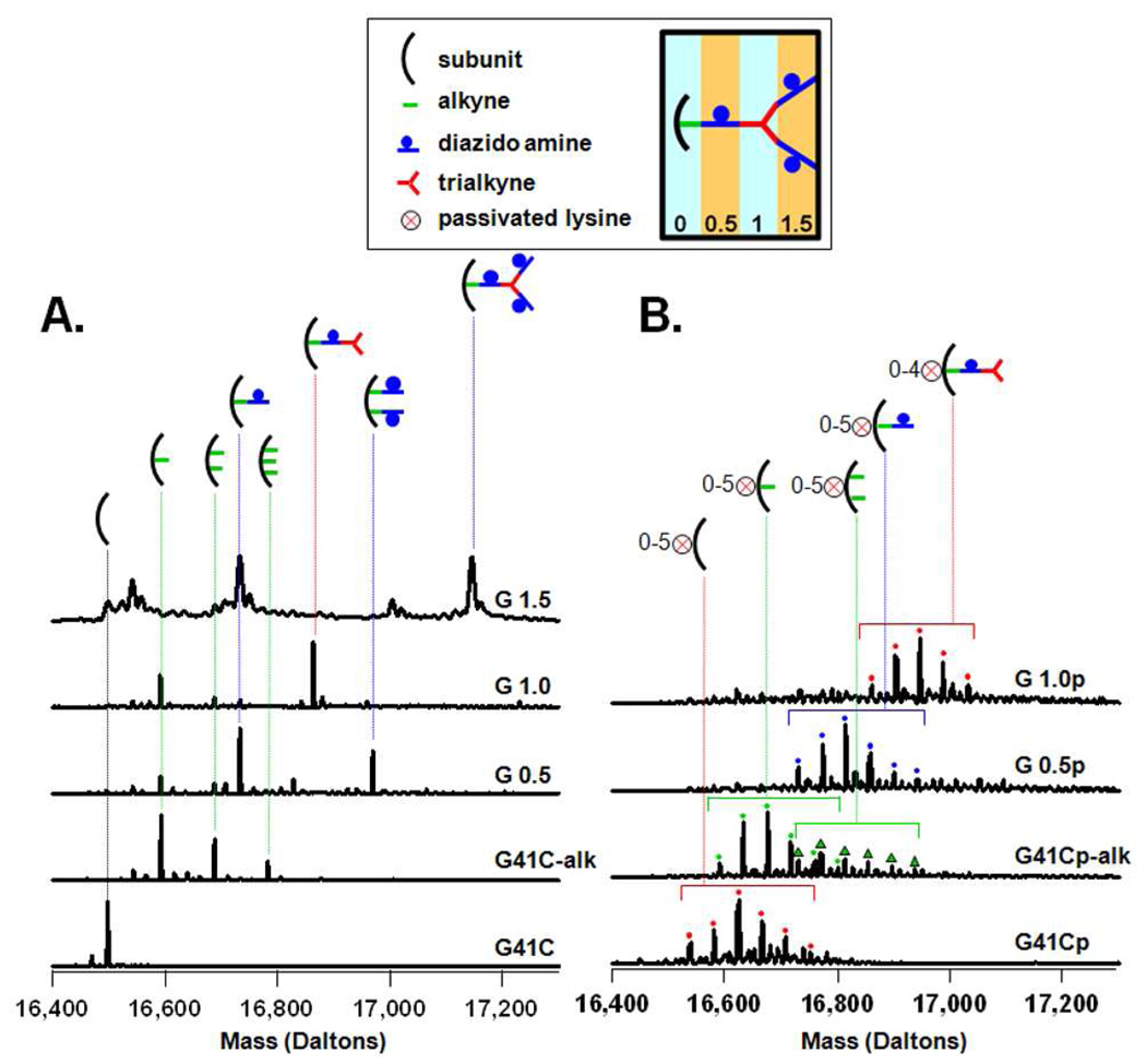
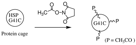
Labeling of HspG41C with a bromo-alkyne (N-propargyl bromoacetamide) to produce G41C-alkyne introduced 0 to 3 alkyne moieties per G41C subunit with the mono alkyne derivative being the major product, as determined by mass spectrometry. Mass added to subunits of G41C for G 0.0 to G 1.5 are shown in Figure 2A. The bromo-alkyne is expected to react primarily with the sulfhydryls of the cysteine that are presented in the interior cavity of G41C.40 However, bromoactetates and bromoacetamides can also react with the primary amine of lysine residues and with the imidazole ring of histidine residues.41,42 There are 11 lysines and one histidine per subunit of G41C. In order to limit the extent of reaction of the bromo-alkyne with the numerous lysine residues they were passivated by a reaction with a small NHS ester (N-hydroxysuccinimide acetate) according to equation 3. Reaction with the NHS ester produced a clustered distribution of masses corresponding to addition of up to 6 acetyl groups on monomeric subunits of the protein cage (Figure 2B). Compared to the non-passivated cage (Figure 2A), there was a reduction in the proportion of subunits that were labeled with two alkyne groups in G 0.0 and no subunits with three alkynes added were detected in the passivated samples. In subsequent reactions passivated cage-alkyne derivatives were treated in parallel with non-passivated cages to produce G0.5p, G1.0p, G1.5p, G2.0p and G2.5p generations.
Figure 2.
Characterization of the first steps in synthesis using LC/MS to determine masses added to protein cage subunits (A,B). Deconvoluted mass spectra of the non-passivated (A) and passivated (B) preparations. The horizontal brackets in B indicate a group of subunits bound to the same click reaction product, but containing 5 to 6 amines passivated with the acetyl group. The S/N ratio of the spectrum from the passivated G 1.5p preparation was too low to permit accurate deconvolution.
Generations G 0.0, G 0.5 and G 1.0 of the non-passivated (Figure 2A) and passivated protein cages (G 0.0p, G 0.5p and G 1.0p, Figure 2B) exhibit a similar trend in mass spectrometric data. As the polymer is extended, by adding the diazido amine followed by the trialkyne, the mono derivative species (one functional group per monomeric subunit) becomes dominant. This trend is more pronounced for the passivated cage. Subunits of G 0.5 and G 1.0 of the passivated cage have only one addition per subunit (Figure 2B) whereas a small proportion of subunits of G 0.5 of the non-passivated cage have two added functional groups per subunit.
A possible explanation for the disappearance of subunits with more than one added group is that the extra groups are initially added to histidine and/or lysine residues that are exposed to the exterior surface of the protein cage. Cages that incorporated these subunits might then be excluded from the preparations as a result of formation of inter-cage bonds through click reactions which lead to cage precipitation and/or aggregation. In this scenario, the passivated cages should be less prone to bromo-alkyne labeling on their exterior surface and therefore should have less precipitation and a higher percent yield of the reaction. This is the case, and the percent yield of reactions G 0.5, G 1.0 and G 1.5 for the passivated preparations are higher than for the non-passivated cages by an average of 12% for the three reactions. Also, these precipitated or aggregated cages would likely be removed from the entire synthesis by the purification process which follows each click reaction. Size exclusion chromatography, dynamic light scattering and transmission electron microscopy data presented below show that the cage’s exterior diameter is relatively uniform across all generations which is consistent with the idea that if exterior polymer growth occurs on a cage, these cages are then removed from the synthesis.
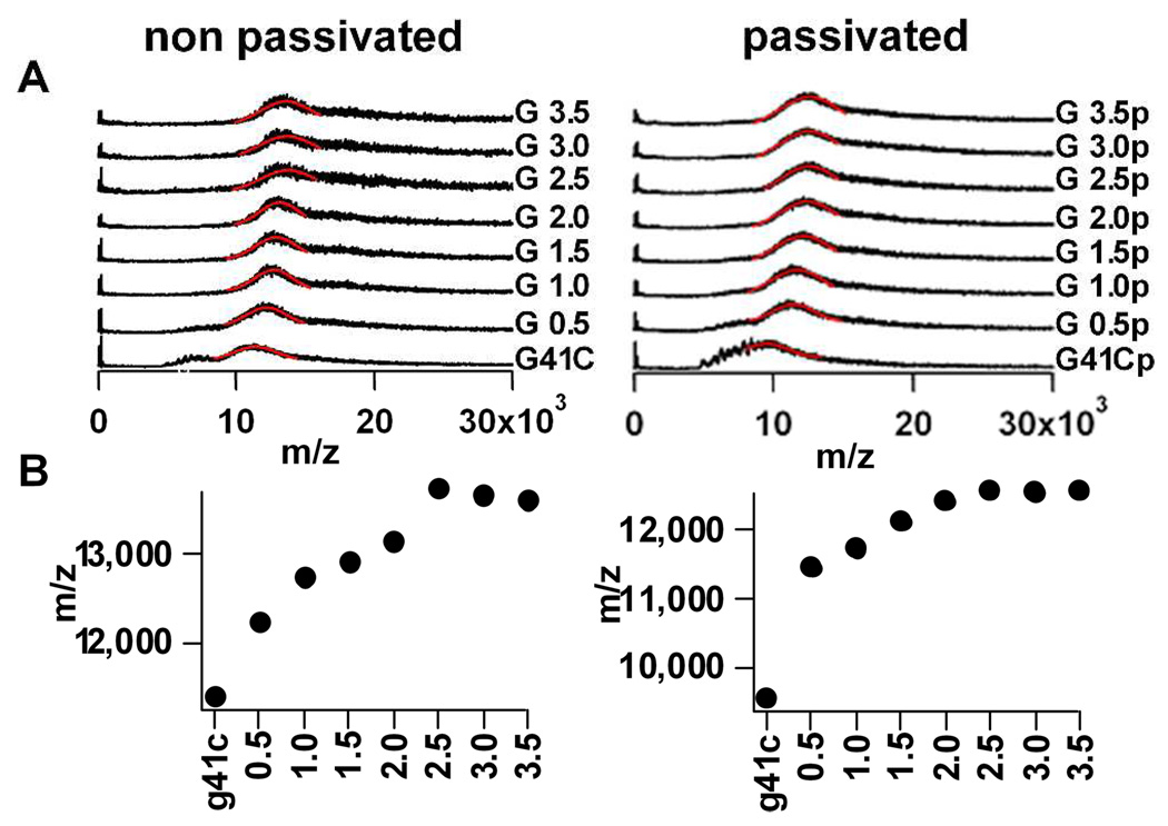
MS spectra obtained under conditions that allow detection of the intact G41C protein cage are shown in Figure 3 for G 1.0 through G3.5 (non-passivated and passivated, ±p). Under these conditions the spectra exhibit a broad band that is a composite of unresolved ion peaks originating from a range of charge states of the intact cage (Figure 3A).43,44 Since the ion peaks were unresolved, a definitive mass could not be assigned to the intact cage for the different generations. However, the shift toward higher m/z values of the broad band that corresponds to the intact cage indicates that mass is likely being added to the cage as the polymer is extended from G 0.0 to G 2.5 (±p) (Figure 3B). The increase in m/z values reached a plateau at generation G 2.5 and this suggests that the mass of the cage remains unchanged at G 2.5 and thereafter (±p). Therefore no additional labeling was observed in G3.0 and G3.5 suggesting that polymer growth was limited by the size constraints of the cavity.
Figure 3.
Characterization of polymer addition to the protein cage using MS tuned to detect the entire intact cage (A). Spectra of non-passivated and passivated preparations showing, from bottom to top, G41C, and G 0.5 through G3.5; Gaussian curve fits to bands originating from the intact cage (solid red lines) were used to obtain an m/z value for each spectrum; (B) Plots of m/z values obtained from each spectrum in A showing an increase in m/z with increasing generation that plateaus at G 2.5.
Inter-subunit crosslinking was observed first at G 1.0
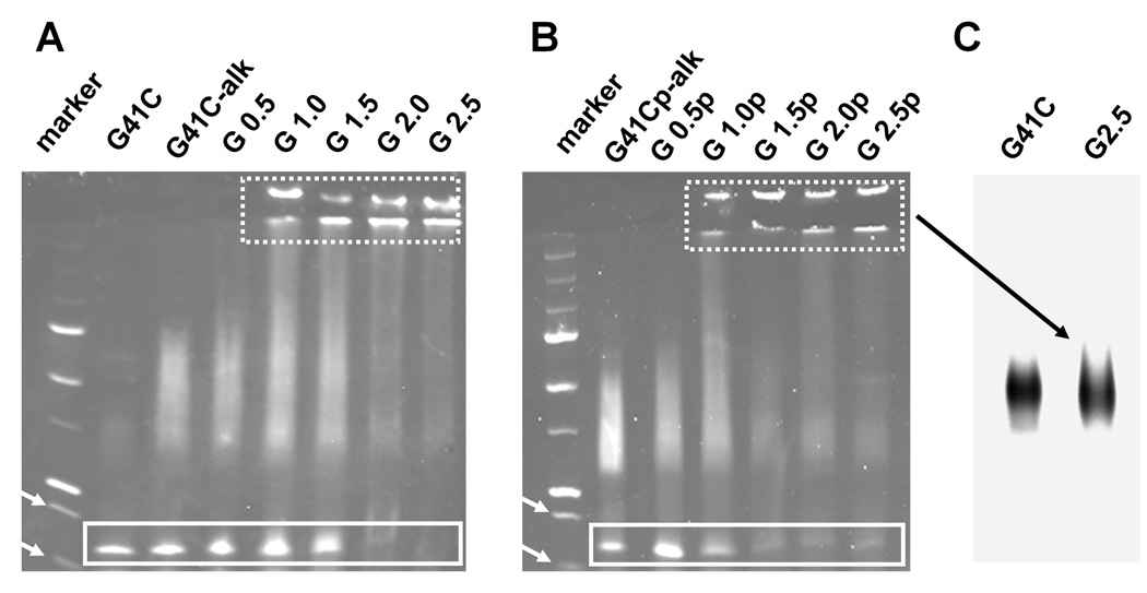
The disappearance of the subunit signal in conventional LC/MS spectra was interpreted as resulting from formation of inter-subunit (intra-cage) covalent crosslinks conferred by extension of the polymer into the interior cavity of the protein cage. SDS-polyacrylamide gel electrophoresis (SDS-PAGE), performed under conditions that dissociate the native protein cage into subunits, was used to support this interpretation (Figure 4). SDS-PAGE analysis shows that, with equivalent loading of the wells, the monomeric subunit band at approximately 16.5 kDa is abruptly reduced in intensity between G 1.5 and G 2.0 for the non-passivated cage and progressively reduced between G 0.5p and G 1.5p for the passivated cage. The appearance of stained protein that was too large to migrate into the gel corresponds to the reduction in the monomeric subunit band intensity. Some of this protein was retained in the well and some migrated to the boundary between the stacking and running gel. Protein cage loaded onto the gels was first purified by size exclusion chromatography (SEC) which removes inter-cage aggregates. Thus, our interpretation of the SDS PAGE is that this larger molecular weight protein material is protein cage in which a substantial proportion of the monomeric subunits have been internally covalently crosslinked via intra-cage crosslinks conferred by the polymer. According to this interpretation the dendritic polymer structure first begins cross linking protein cage subunits at G 1.0. Although there is some appearance of higher molecular weight protein at G 0.5, which might indicate cross linking between protein cage subunits, this diffuse mobility shift toward upper regions of the gel is observed even in preparations in which only an alkyne has been added to the subunits suggesting that the alkyne promotes some interactions between subunits. In order to further characterize the protein material that was too large to enter the gel the protein preparations from G 2.5 were analyzed on an agarose gel under non-denaturing (native) conditions. Results from both non-passivated and passivated preparations yielded a single band that migrated to the same position as the native protein cage (Figure 4C), indicating that the large molecular weight protein material was indistinguishable in size from the native protein cage and likely corresponds to extensively crosslinked Hsp subunits within the cage-like architecture.
Figure 4.
Evidence for crosslinking of protein cage subunits using denaturing gel electrophoresis (A,B). SDS-PAGE of the non-passivated (A) and passivated (B) generations stained with coomassie. The monomeric subunit (16.5kDa) migrates to a position between the molecular weight markers at 20 and 15 kDa (indicated by white arrows); bands originating from the monomeric subunit are boxed with a solid line. High molecular weight protein that was too large to migrate into the running gel became evident for generations greater than G 0.5; bands from this high molecular weight protein appear at both the boundary between the well and the stacking gel and at the boundary between the stacking gel and the running gel (enclosed by box with the dashed line). (C) High molecular weight protein from the passivated G 2.5p generation was very similar in size to the native protein as indicated by its migration on an agarose gel; results from the non-passivated preparation were identical.
Shape and size distribution of protein cages polymerized with dendritic-like structures
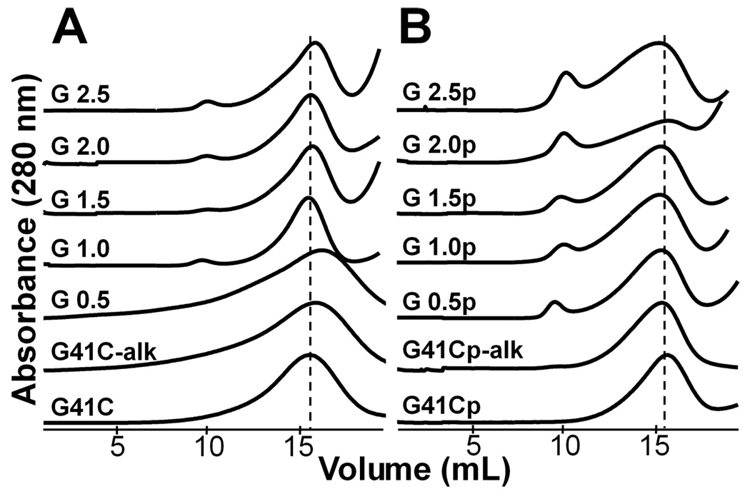
SEC elution profiles, transmission electron microscopy (TEM) images and size distributions determined by dynamic light scattering (DLS) all indicate that the G 0.5 through G 2.5 generations initiated from both passivated and non-passivated protein cage were monodisperse and very similar in size to the native protein cage. SEC was used to purify samples characterized by MS, gel electrophoresis, TEM and DLS. The SEC elution profiles of the polymerized Hsp used for further analysis is nearly identical in elution volume and peak shape to that of the native cage for G 0.5 through G 2.5 (±p) preparations (Figure 5).
Figure 5.
Size distributions of the protein cages of various generations of non-passivated (A) and passivated (B) protein cage preparations are all nearly identical to the native cage according to the SEC elution profiles. The peak position of the band containing the protein cage is shown by the broken line.
The elution profile of G 1.0 through G 2.5 for the non-passivated and G 0.5 through G 2.5 for the passivated preparations exhibit a peak corresponding to higher molecular weight material that elutes at approximately 10 mL and corresponds to roughly 5% of the sample based on peak areas of the SEC profiles. This is consistent with our interpretation that inter-subunit crosslinking occurs and can lead to aggregate formation. Some of this aggregated material may remain soluble and be carried through the preparation to the SEC purification. This population only represents a small percentage of the total (~5%), since a substantial portion of these inter-cage aggregates either precipitated from solution or were retained in the column.
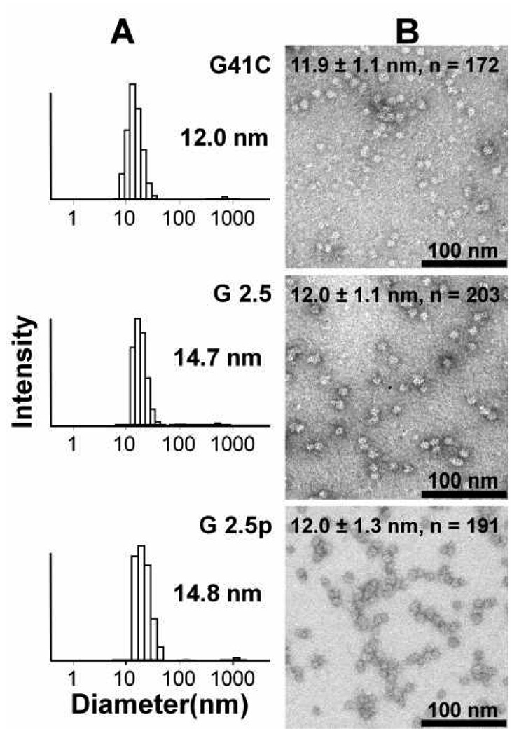
DLS confirms that the size distribution in G 0.5 to G 2.5 (±p) SEC-purified cage preparations is nearly identical to the native cage (Figure 6A and Figure S1). Results of DLS also indicate that only trace amounts of large inter-cage aggregates are present in the purified preparations. TEM images provide more direct evidence that G 0.5 to G 2.5 (±p) SEC-purified cage preparations are monodispersed, and that they have the same shape and size as the native protein cage (Figure 6B and Figure S2). Measurements of the particles from multiple images taken from multiple preparations resulted in mean diameters of 11.9 ± 1.1, n = 172 (G41C); 12.0 ± 1.1 (G 2.5), n = 203; 12.0 ± 1.3, n = 191 (G 2.5p) in units of nanometers, indicating that the particles are uniform across all generations.
Figure 6.
Comparison of the size and shape distribution of the native protein cage (G41C) with non-passivated G 2.5 and passivated G 2.5p generations evaluated by DLS (A) and TEM (B). Numbers in (A) are the mean hydrodynamic diameter of the DLS distribution. Protein cages were stained with 2% uranyl acetate for TEM visualization as described in the experimental section and measurement are included on the top of each TEM image (Diameter ± Standard Deviation, n = number of particles measured).
In general we have found that changing the properties of the exterior surface of protein cages by functionalization can alter the DLS-derived hydrodynamic radius. One possible explanation for this is that properties of the exterior surface influence formation of transient aggregates which, in turn, has been shown to influence results of DLS measurements.45 It is noteworthy in this respect that the DLS results yield a diameter of approximately 14 nm for the passivated G41C, while the native cage yields a diameter of about 12 nm (see Fig. S1, Supplemental Materials). Thus merely adding the small passivating group to the cage influences the DLS-derived diameter.
Taken together results of SEC, TEM and DLS analyses strongly suggest that in the purified preparations the polymer extends into the interior of the cage from the polymer initiation point at the genetically engineered cysteine of G41C.
Internally directed branched polymers increased the stability of protein cages
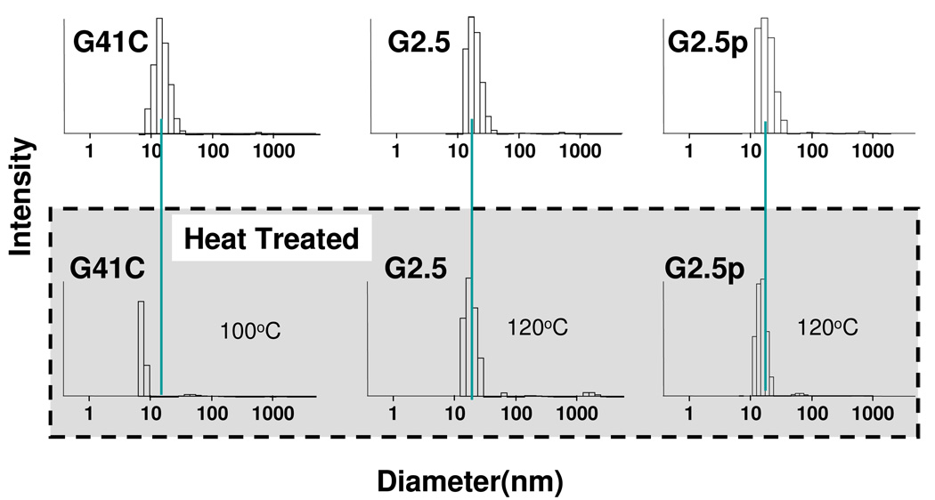
The monomeric subunits that comprise protein cages are associated by non-covalent bonds. The native protein cage looses its quaternary structure at temperatures greater than approximately 70 °C. In principle, formation of intra-cage crosslinks between subunits by covalent bonds should stabilize the protein cage. We determined the robustness of the G 2.5(±p) cage preparations by subjecting them to heat. HspG41C, G 2.5 and G 2.5p samples were heated to 35, 45, 55, 65, 75, 85, and 100 °C for 10 min at each temperature separately and analyzed by DLS (Figure S1). DLS data show HspG41C cage maintained its integrity up to 70 °C, while at 75 °C and above the cage was degraded into smaller components (Figure S1). When subjected to a 100 °C for 10 min the native Hsp protein cage did not retain any species in the size range expected for intact cage either by DLS (Fig 7) or SEC analysis (Figure S3A). In contrast, when G 2.5 (±p) generations were heated to 120 °C for 30 min the size distributions, by DLS (Fig 7) and SEC (Figure S3B and S3C) were almost identical to the undisturbed native cage and no precipitated material was observed.
Figure 7.
G 2.5(±p) cage generations exhibited exceptional stability upon exposure to heat according to DLS data. Results for the unheated native cage (G41C) and G 2.5(±p) are in the top row and results for the heat treated cage are in the bottom row. The G41C native cage decomposes upon exposure to 100 °C for 10 min while non-passivated G 2.5 and passivated G 2.5p generations remain intact upon exposure to 120 °C for 30 min. The green line indicates the position of the mean diameter of the unheated generations.
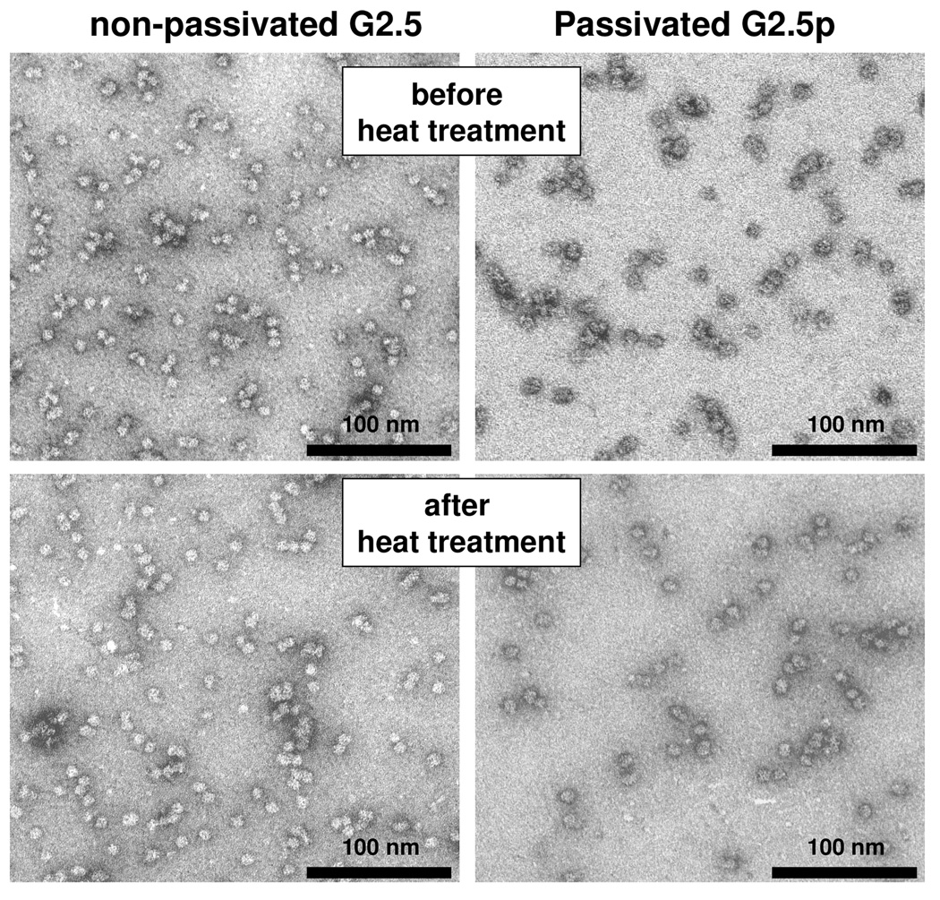
TEM images of heat treated cages corroborate the DLS and SEC results indicating that the robustness of the G 2.5(±p ) generations was greatly enhanced as a result of the covalent crosslinking of the subunits by the internal branched polymer (Figure 8). While the quaternary structure of the native protein cage, subjected to ≥75 °C for 10min, was disrupted to the extent that no intact cage could be distinguished in TEM images (data not shown), Figure 8 shows that G 2.5 (±p) particles were still intact when subjected to 120 °C for 30 min. The mean size distributions obtained by measuring the uranyl acetate stained objects are 12.4±0.8nm for non-passivated and 12.7±0.8nm for passivated particles. Thus, DLS, SEC elution profiles and TEM results corroborate the enhanced thermal stability of the cages as a result of internal polymer crosslinking.
Figure 8.
G 2.5(±p) generations maintain their shape upon exposure to 120 °C for 30 min. TEM preparations were strained with 2% uranyl acetate as described in the Experimental section.
Amine functional groups on dendritic structures are addressable
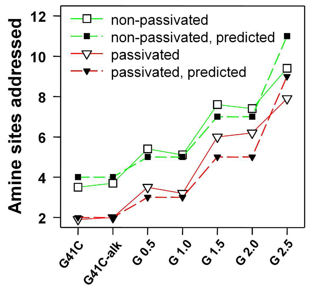
A primary objective of this work was to synthesize a size constrained architecture that could serve as a scaffold for dense functional group display, while still being sufficiently porous to allow free access of small molecules into the interior. The dendritic structure was designed so that the success of this objective could be tested by labeling primary amines on the diazido amine monomer units. To evaluate how many amine groups on the dendritic structures were addressable we labeled them with fluorescein isothiocyanate (FITC) which can be detected using UV-VIS spectroscopy and is also similar in size to many anti-cancer drugs. The results are summarized in Figure 9. Using the extent of FTIC labeling of the native cage preparations as an initial value, the number of sites labeled with FITC, according to the UV-VIS absorbance measurements, is strikingly similar to the number of predicted addressable sites based on the polymer design strategy (Figure 1C). For G 2.5 the total number of FITC molecules attached to the cage was 226 and 190 for non-passivated and passivated generations respectively. Subtracting out the contribution of FITC added to the native cage indicates that 142 (G 2.5) and 144 (G 2.5p) FTIC molecules were covalently bound to the polymer amines. Since the polymer was designed to introduce 168 amines into the cage, the FITC labeling results indicate that approximately 85% of the newly installed amines in the cavity were addressable. According to the predicted polymer growth scheme (Figure 1C) no pendent amine groups should be introduced for G41C-alk, G 1.0 and G2.0. This is in good agreement with the data presented in Figure 9 for both passivated and non-passivated preparations since no additional amines were added in these reactions. SDS-PAGE gels indicated that the added fluoresceins were covalently bound to the protein cages (Figure S4 and Figure S5). As expected the passivated cages, prior to polymerization, were less reactive to the FITC than the non-passivated cages. The data indicate that four and two intrinsic lysines per subunit were reactive toward FITC in the non-passivated and passivated native cage preparations respectively. These data suggest that there are two lysines that are reactive toward FITC but not reactive toward the acetyl NHS ester used as a passivating reagent. This result is reasonable since the reaction with the FITC reagent was performed at a higher pH (pH 8.4 as opposed to pH 7.3 for the NHS-ester passivation reaction).
Figure 9.
Number of amine sites that were labeled with FITC according to the UV-VIS absorbance analysis. Also the predicted number of addressable amines, according to the synthesis scheme presented in Figure 1C, is shown.
Conclusions
We have designed and implemented a strategy for synthesizing a branched structure, via azide alkyne cycloaddition reactions, that projects into the interior cavity of a genetically engineered protein cage. Protein cages encapsulating the branched polymer maintain their native shape and size distribution. However, they differ from native protein cages in that their quaternary structure is considerably more stable, being able to withstand exposure to heat treatment that completely disrupts the native cage architecture. This dramatically expands the synthetic range and utility of these biological templates. The enclosed polymer introduced addressable sites that can be used to enhance the carrying capacity of the nanoplatform. The FITC labeling of these cages show 142 to 144 amines (~85%) of the 168 newly installed pendant primary amine groups were addressable. The use of this protein cage approach has permitted the generation of branched polymer structures restricted to a precisely defined nanometer scale. Furthermore, the introduced addressable sites provided by this type of branched polymer exist in a molecular environment to which the rigidity, functionality and spacing are all controllable parameters based on monomer design. Application of these materials towards drug delivery and imaging are being explored.
Experimental
Materials
2-Bromo-1-bromomethyl-ethyl amine hydrobromide, bromoacetyl bromide, propargyl amine, N-hydroxysuccinimideacetate, and sodium azide were purchased from Sigma and used as received. The catalyst [Cu(CH3CN)4](OTf) was synthesized as previously described.46 THF was distilled over benzophenone/sodium metal. All other chemical reagents were obtained from commercial suppliers and used as received, unless indicated otherwise.
Synthesis of reagents for polymerization
Synthesis of N-propargyl bromoacetamide
N-Propargyl bromoacetamide was synthesized according to an established procedure (Eq 1).29 In a solution of bromoacetyl bromide (1.0g, 4.954mmol) THF propargyl amine (0.274g, 4.954mmol) was added dropwise in a two neck flask under nitrogen. After stirring for 12 h at 0°C, the mixture was rotary evaporated and the crude product was purified by column chromatography over silica gel using hexane, methylene chloride and ethylacetate in a ratio of 6:3:1. After evaporation of the solvent, N-propargyl bromoacetamide was obtained as a slightly yellowish solid. The yield was 0.55g (60%) and the product was characterized by 1H-NMR and LC/MS. 1H-NMR (500 MHz): δ (in CDCl3) 6.83(s, br, NH), 3.83(s, 2H), 3.34(q, 2H) and 2.1(m, 1H). LC-MS: M+H 176.90(found), M+H 176.96(calculated).
 |
Eq 1 |
Synthesis of 2-azido-1-azidomethyl-ethylamine
2-Bromo-1-bromomethyl-ethyl amine, hydrobromide (100mg, 0.336mmol) and sodium azide (77mg, 1.18mmol) were stirred together in water (5mL) in a small two neck flask fitted with a reflux condenser at 80 °C for 15 h (Eq 2). After the reaction mixture was cooled to room temperature, 2mL aqueous 5% KOH was added and the mixture was further stirred for another 2 hours and then extracted with methylene chloride (2× 5mL). An additional 3mL of 5% aqueous KOH was added to the aqueous phase, and extracted again with methylene chloride (3× 5mL). The combined organic layers were dried with Na2SO4 and filtered. The solvent was evaporated at 25 °C under reduced pressure using a rotatory evaporator and the product, 2-azido-1-azidomethyl-ethylamine was obtained as a clear liquid in 80% (38mg) yield. The product was characterized by 1H-NMR and LC/MS. 1H-NMR (500 MHz): δ (in CDCl3) 3.5 (d, 4H), 3.0 (m, 1H), 1.8 (s, 2H, NH2). LC-MS: M+H 142.07(found), M+H 142.08(calculated).
 |
Eq 2 |
Synthesis of the dendritic structure of in the cavity of HspG41C
The overall synthetic scheme for both non-passivated and passivated cages is summarized in Scheme 1.
(A) Passivation of lysine residues with NHS ester of acetic acid
HspG41C cage (6.11mg/mL, 370µM) in 1mL of 100mM HEPES, 50mM NaCl, pH 7.3 was treated in a small vial with N-hydroxysuccinimide acetate, (3.7mM, 0.6mg dissolved in 10µL DMF, 10-fold excess relative to subunit protein) for 1 hour at room temperature, followed by overnight incubation at 4 °C. The acetyl labeled cage, HspG41C(COCH3) was purified from unbound small organic molecules by SEC and concentrated to 1mL by microamicon ultrafiltration with a 100K Mw cut off membrane. The concentration of the intact cage was determined by OD280 as 4.8mg/mL, yield 80%. The passivated cage was characterized by LC/MS. LC/MS analysis shows 1 to 6 lysine residues are passivated with acetyl group.
 |
Eq 3 |
(B) HspG41C-alkyne conjugate
HspG41C (±p) cages (6.11mg/mL, 370µM) in 1mL of 100mM HEPES, 50mM NaCl, pH 6.5 were reacted in a small vial with N-propargyl bromoacetamide (3.7mM, 0.65mg dissolved in 10µL DMF, 10-fold excess relative to subunit protein) for 1 hour at room temperature, followed by overnight incubation at 4 °C. The alkyne labeled HspG41C cages were purified from the unreacted excess alkyne molecule by SEC and concentrated to 1mL by microamicon ultrafiltration with a 100K Mw cut off membrane. The concentrations of the intact cages were determined by OD280 in the range 4–4.5mg/mL, yield 65–74%. The number of attached alkyne molecule per subunit protein was determined by LC/MS.
(C) Preparation of HspG41C-alkyne-azide bioconjugates(G 0.5±p)
Protein cage derivatives G41C(±p)-alkyne decorated with terminal alkyne inside the cages were coupled with 2-azido-1-azidomethyl-ethylamine through Cu-catalyzed azide-alkyne coupling (Cu.AAC) reaction7 as follows. Under a nitrogen atmosphere in a glove box, HspG41C (±p)-alkyne (7.0mg/mL, 424µM in protein subunit) and 2-azido-1-azidomethyl-ethylamine (8.54mmol, 0.6 mg dissolved in 10 µL DMF, 10-fold excess per subunit protein) were mixed in 1mL degassed 100mM HEPES, 50mM NaCl, pH 7.5 buffer in a 4mL glass vial. A 100mM stock of Cu(CH3CN)4(OTf) in degassed CH3CN and a 100mM stock of sulfonated bathophenanthroline ligand in degassed 100mM HEPES, 50mM NaCl, pH 7.5 buffer was prepared. A 1:2 mixture of Cu(CH3CN)4(OTf) and the ligand was prepared and added to the reaction mixture to achieve a final concentration of 2 mM Cu(I) and 4 mM ligand. The reaction vials were sealed and stirred for 1 hour at room temperature and incubated overnight with stirring at 4 °C. After the reaction the mixture was treated with 40µl of 0.5M EDTA, pH 8.0 (10-fold excess to that of Cu(I) reagent) to chelate and remove Cu ions associated with the cage derivatives. The resultant alkyne conjugated derivatives (G 0.5 ±p) were purified from the small molecules and Cu complexes by SEC, concentrated by microamicon ultrafiltration with a 100K Mw cut off membrane followed by washing with 100mM HEPES, 50mM NaCl, pH 7.5 buffer twice to remove any carry over dissociated subunit protein and small molecules from the SEC. The intact protein cage recovery was 78% (5.5mg/mL) for non-passivated conjugate and 90% (6.3mg/mL) for passivated conjugate as determined by OD280 of cage derivatives. The HspG41C-alkyne-azide bioconjugates (G 0.5±p) were characterized by LC/MS.
(D) Preparation of HspG41C-alkyne-azide-alkyne bioconjugate(G 1.0±p)
Protein cage derivatives HspG41C(w±p-alkyne-azide (G 0.5 ±p) with one intact azide inside the cage were subjected to Cu.AAC reaction with tripropargyl amine under similar conditions as described above for generation G 0.5 (±p). HspG41C(w±p)-alkyne-azide( 5.5mg, 333µM for non-passivated or 7.0mg, 427 for passivated derivatives) in 1mL degassed 100mM HEPES, 50mM NaCl, pH 7.5 buffer and 20 fold excess tripropargyl amine (10.99mM, 1.32mg dissolved in 10uL DMF for non-passivated cage; 14.1mM, 1.9mg dissolved in 10 µL DMF for passivated cage) were reacted together in a small glass vial under nitrogen in a glove box in degassed 1mL 100mM HEPES, 50mM NaCl, pH 7.5 buffer in the presence of 2mM of Cu(CH3CN)4(OTf) (0.74mg) and 4mM sulfonated bathophenanthroline ligand (2.40mg) as the final concentration. As in the above reaction the vials were sealed and stirred for 1 hour at room temperature, and incubated overnight with stirring at 4 °C. After the reaction the mixtures were treated with 40ul of 0.5M EDTA, pH 8.0.The conjugated derivatives (G 1.0 ±p) were purified by SEC, concentrated by microamicon ultrafiltration with a 100K Mw cut off membrane followed by washing with 100mM HEPES, 50mM NaCl, pH 7.5 buffer. The intact protein cage recovery was 75% (4.1mg/mL) for non-passivated conjugate and 90% (6.3mg/mL) for passivated conjugate as determined by OD280. The HspG41C(±P)-alkyne-azide-alkyne bioconjugates (G 1.0 ±p) were characterized by LC/MS.
(E) Preparation of HspG41C-alkyne-azide-alkyne-azide conjugate(G 1.5±p)
Protein cage derivatives HspG41C(±p)-alkyne-azide-alkyne (G 1.0 ±p) with two terminal alkyne inside the cage were subjected to Cu.AAC reaction with 2-azido-1-azidomethyl-ethylamine under similar conditions as described above. HspG41C(±p)-alkyne-azide-alkyne (7.0mg, 424µM in protein subunit) and 2-azido-1-azidomethyl-ethylamine (8.54mmol, 1.2mg dissolved in 10 uL DMF, 20-fold excess per subunit protein) were reacted together in a small glass vial in degassed 1mL 100mM HEPES, 50mM NaCl, pH 7.5 buffer in the presence of 1mM of Cu(CH3CN)4(OTf) (0.74mg, dissolved in degassed CH3CN) and 2mM sulfonated bathophenanthroline ligand (2.4mg, dissolved in degassed HEPES, pH7.5 buffer) as the final concentration. The vials were sealed and stirred for 1 hour at room temperature, and incubated overnight with stirring at 4 °C. After the reaction the mixture were treated with 40µl of 0.5M EDTA, pH 8.0 (10 molar excess to that of Cu(1) catalyst added).The conjugated derivatives (G 1.5 ±p ) were purified by SEC, concentrated by microamicon ultrafiltration with a 100K Mw cut off membrane followed by washing with 100mM HEPES, 50mM NaCl, pH 7.5 buffer). The intact protein cage recovery was 75% (5.3mg/mL) for non-passivated conjugate and 85% (6.0mg/mL) for passivated conjugate as determined by OD280. The HspG41C(±p)-alkyne-azide-alkyne-azide bioconjugates (G 1.5 ±p) were characterized by LC/MS.
(F) Preparation of HspG41C-alkyne-azide-alkyne-azide-alkyne conjugate (G 2.0±p)
Protein cage derivatives HspG41C(±p)-alkyne-azide-alkyne-azide (G 1.5 ±p) with multiple azide functionality inside the cage were subjected to Cu.AAC reaction with 50 fold molar excess( relative to subunit protein) tripropargylamine in 100mM HEPES, 50mM NaCl, pH 7.5 buffer under similar conditions as mentioned above to afford G 2.0 (±p). After the EDTA treatment, the cage derivatives were purified over SEC and concentrated by microamicon ultrafiltration with a 100K Mw cut off membrane followed by washing with 100mM HEPES, 50mM NaCl, pH 7.5 buffer. The intact protein cages recovery was 75–80% (3.5–4.0mg obtained out of 5.0mg starting G 1.5 ±p generation) as determined by OD280 of cage derivatives.
(G) Preparation of HspG41C-alkyne-azide-alkyne-azide-alkyne-azide conjugate(G 2.5 ±p)
Protein cage derivatives HspG41C(±p)-alkyne-azide-alkyne-azide (G 2.0 ±p) with multiple terminal alkynes inside the cage were subjected to Cu.AAC reaction with 50 fold molar excess (relative to subunit protein) 2-azido-1-azidomethyl-ethylamine in 100mM HEPES, 50mM NaCl, pH 7.5 buffer under similar conditions as mentioned above to provide G 2.5 (±p). After the EDTA treatment, the cage derivatives were purified over SEC and concentrated by microamicon ultrafiltration with a 100K Mw cut off membrane followed by washing with 100mM HEPES, 50mM NaCl, pH 7.5 buffer. The intact protein cages recovery was 65–75% (3.25–3.75mg obtained out of 5.0mg starting G 1.5 ±p materials) as determined by OD280 of cage derivatives.
(H) Attempted preparation of G3.0±p and G3.5±p generations
G 2.5 (±p) generations were subjected to Cu.AAC reaction with 50 fold molar excess (relative to subunit protein) tripropargylamine in 100mM HEPES, 50mM NaCl, pH 7.5 buffer under similar anaerobic conditions and purified as mentioned above to provide G3.0 (±p). Similarly G3.0 (±p) was treated with 50 fold molar excess (relative to subunit protein) 2-azido-1-azidomethyl-ethylamine in 100mM HEPES, 50mM NaCl, pH 7.5 buffer under similar conditions and purified as mentioned above to provide G3.5 (±p)
sHspG41C Cages Purification and Characterization
Small Hsp G41C cage was purified from an E. coli heterologous expression system as previously described32. One liter cultures of E. coli (BL21 [DE3] B strain) containing pET-30a(+) MjHsp16.5 plasmid were grown overnight in LB plus kanamycin medium (37°C, 220 rpm). Cells were harvested by centrifugation at 3700 × g for 15 min and resuspended in 30 ml of 100 mM HEPES, 50 mM NaCl, pH 8.0. Lysozyme, DNase, and RNase were added to the final concentrations of 50, 60, and 100 µg/ml respectively. The sample was incubated for 30 min at room temperature, French pressed (American Laboratory Press Co., Silver Springs, MD), and sonicated on ice (Branson Sonifier 250, Danbury, CT, power 4, duty cycle 50%, 3 × 5 min with 3 min intervals). Bacterial cell debris was removed via centrifugation for 20 min at 12,000 × g. The supernatant was heated for 15 min at 65°C, thereby denaturing many E. coli proteins. The supernatant was centrifuged for 20 min at 12,000 × g and purified by gel filtration chromatography (Superose-6, Bio-Rad Duoflow, Hercules, CA). HspG41C, HspG41C(±p)-alkyne, HspG41C(±p) -alkyne-azide(0.5 ±p), HspG41C(±p)-alkyne-azide-alkyne(G 1.0 ±p), HspG41C(±p)-alkyne-azide-alkyne-azide(G 1.5 ±p) and HspG41C(±p)-alkyne-azide-alkyne-azide-alkyne( G 2.0 ±p) HspG41C(±p)-alkyne-azide-alkyne-azide-alkyne-azide (G 2.5 ±p) protein cages were routinely characterized by size exclusion chromatography (SEC) (Superose 6, Bio-Rad Duoflow), DLS (Brookhaven 90Plus, Brookhaven, NY), TEM (Leo 912 AB), SDS-PAGE, and mass spectrometry (NanoAcquity/Q-Tof Premier; Waters, Milford, MA). Protein concentration was determined by absorbance at 280 nm using the published extinction coefficient (9322 M−1 cm−1) 31
Labeling of G41C, G41C(±p )-alkyne, G 0.5 (±p ),G 1.0(±p), G 1.5(±p), G 2.0(±p) and G 2.5(±p) with Fluorescein isothiocyanate(FITC) and calculations used to generate Figure 9
200ul (2mg/mL) of each cage derivates were incubated overnight at room temperature with a 15-fold molar excess of FTIC per subunit of cages in 100mM HEPES, 50 mM NaCl at pH 8.4. The FITC labeled products were purified by Micro Bio-Spin Columns packed with Bio-Gel P-30 polyacrylamide.
The molar concentrations of FITC molecules attached to the subunit derivatives were determined for each construct by comparing the absorbance at 495 to a standard curve. The standard curve (A495) was made from a series of solutions containing known concentrations of FITC molecules. The protein concentrations (grams/liter) of the cage derivatives were determined by BCA™ protein assay Kit (Pierce, product number 23227) following the manufacturer's instructions and the subunit molar concentration was calculated by dividing protein mass concentration (grams/liter) by the molecular weight of the subunit (16,498 grams/mole). Finally the number of FITC molecules per subunit was calculated by dividing the molar concentration of FITC by the molar concentration of the subunit.
The predictions were made by fixing the starting points (G41C and G41C-alk (±p) ) of the predicted traces to integer values nearest to their corresponding experimentally determined values. The predicted number of amines addressed per subunit for each generation was then calculated by adding the number of diazido amines present at a given generation, based on Figure 1C, to the experimentally determined starting point.
Mass Spectrometry
MS analyses were performed on a Q-Tof Premier (Waters; Waters, Milford, MA). HspG41C(±p), HspG41C(±p)-alkyne, G 0.5(±p), G 1.0(±p), G 1.5(±p), G 2.0(±p), G 2.5(±p) (0.1– 2µL, 0.3–2.0 mg/ml) were injected onto a BioBasic SEC-300 (Thermal Electron, Waltham, MA) column and eluted with 40% IPA, 0.1% formic acid. Deconvoluted spectra were generated with the software MaxEnt1 provided by Waters. Small organic molecules were analyzed using C18 column (218TP5115, Vydac,_Deerfield, IL) and eluted with a water–acetonitrile linear gradient (eluent A: 0.1% formic acid in water; eluent B: 0.1% formic acid in acetonitrile).
Mass analyses of the intact Hsp cage derivatives were carried out on samples in 10 mM triethylammonium acetate(TEAA) (pH 6.8) buffer47. Spectra were acquired in the range of m/z 50–30,000 by directly infusing samples into the mass spectrometer at a flow rate of 15 µL/min. Source and desolvation temperatures were 80 °C and 120 °C, respectively. Collisional focusing, which facilitated the focusing and transmission of ionized cages in vacuo, was achieved by increasing the source pressure to approximately 7.0 mbar.48 The capillary voltage and the sample cone voltage were 3,000 V and 50 V, respectively. Pressure in the collision cell and the TOF tube were maintained at 1.0 × 10⁻² mbar and 2.0 × 10⁻⁶ mbar, respectively.
Supplementary Material
Figures S1, S2, S3, S4 and S5 are provided as supporting information. These materials are available free of charge via the internet at http://pubs.acs.org.
Acknowledgment
This research was supported by grant from the National Institutes of Health (Grant R21EB005364). We thank Sue Brumfield at the Center for Bio-Inspired Nanomaterials for assisting with TEM images.
References
- 1.Uchida M, Klem MT, Allen M, Suci P, Flenniken M, Gillitzer E, Varpness Z, Liepold LO, Young M, Douglas T. Advanced Materials. 2007;19(8):1025–1042. [Google Scholar]
- 2.Douglas T, Young M. Science. 2006;312(5775):873–875. doi: 10.1126/science.1123223. [DOI] [PubMed] [Google Scholar]
- 3.Gauss GH, Benas P, Wiedenheft B, Young M, Douglas T, Lawrence CM. Biochemistry. 2006;45(36):10815–10827. doi: 10.1021/bi060782u. [DOI] [PMC free article] [PubMed] [Google Scholar]
- 4.Hosein HA, Strongin DR, Allen M, Douglas T. Langmuir. 2004;20(23):10283–10287. doi: 10.1021/la0491100. [DOI] [PubMed] [Google Scholar]
- 5.Kumagai S, Yoshii S, Yamada K, Fujiwara J, Matsukawa N, Yamashita I. Journal of Photopolymer Science and Technology. 2005;18(4):495–500. [Google Scholar]
- 6.Wiedenheft B, Mosolf J, Willits D, Yeager M, Dryden KA, Young M, Douglas T. Proceedings of the National Academy of Sciences of the United States of America. 2005;102(30):10551–10556. doi: 10.1073/pnas.0501497102. [DOI] [PMC free article] [PubMed] [Google Scholar]
- 7.Gupta SS, Kuzelka J, Singh P, Lewis WG, Manchester M, Finn MG. Bioconjugate Chemistry. 2005;16(6):1572–1579. doi: 10.1021/bc050147l. [DOI] [PubMed] [Google Scholar]
- 8.Hooker JM, Kovacs EW, Francis MB. Journal of the American Chemical Society. 2004;126(12):3718–3719. doi: 10.1021/ja031790q. [DOI] [PubMed] [Google Scholar]
- 9.Steinmetz NF, Evans DJ, Lomonossoff GP. Chembiochem. 2007;8(10):1131–1136. doi: 10.1002/cbic.200700126. [DOI] [PubMed] [Google Scholar]
- 10.Flenniken ML, Willits DA, Harmsen AL, Liepold LO, Harmsen AG, Young MJ, Douglas T. Chemistry & Biology. 2006;13(2):161–170. doi: 10.1016/j.chembiol.2005.11.007. [DOI] [PubMed] [Google Scholar]
- 11.Uchida M, Flenniken ML, Allen M, Willits DA, Crowley BE, Brumfield S, Willis AF, Jackiw L, Jutila M, Young MJ, Douglas T. Journal of the American Chemical Society. 2006;128(51):16626–16633. doi: 10.1021/ja0655690. [DOI] [PubMed] [Google Scholar]
- 12.Liepold L, Anderson S, Willits D, Oltrogge L, Frank JA, Douglas T, Young M. Magnetic Resonance in Medicine. 2007;58(5):871–879. doi: 10.1002/mrm.21307. [DOI] [PubMed] [Google Scholar]
- 13.Hooker JM, Datta A, Botta M, Raymond KN, Francis MB. Nano Letters. 2007;7(8):2207–2210. doi: 10.1021/nl070512c. [DOI] [PubMed] [Google Scholar]
- 14.Ensign D, Young M, Douglas T. Inorganic Chemistry. 2004;43(11):3441–3446. doi: 10.1021/ic035415a. [DOI] [PubMed] [Google Scholar]
- 15.Tominaga M, Ohira A, Kubo A, Taniguchi I, Kunitake M. Chemical Communications. 2004;(13):1518–1519. doi: 10.1039/b402984d. [DOI] [PubMed] [Google Scholar]
- 16.Varpness ZB, Shoopman C, Peters JW, Young M, Douglas T. Nano Letters. 2005;5(11):2306–2309. doi: 10.1021/nl0517619. [DOI] [PubMed] [Google Scholar]
- 17.Allen M, Bulte JWM, Liepold L, Basu G, Zywicke HA, Frank JA, Young M, Douglas T. Magnetic Resonance in Medicine. 2005;54(4):807–812. doi: 10.1002/mrm.20614. [DOI] [PubMed] [Google Scholar]
- 18.Allen M, Willits D, Mosolf J, Young M, Douglas T. Advanced Materials. 2002;14(21):1562–1565. [Google Scholar]
- 19.Klem MT, Resnick DA, Gilmore K, Young M, Idzerda YU, Douglas T. Journal of the American Chemical Society. 2007;129(1):197–201. doi: 10.1021/ja0667561. [DOI] [PubMed] [Google Scholar]
- 20.Resnick DA, Gilmore K, Idzerda YU, Klem MT, Allen M, Douglas T, Arenholz E, Young M. Journal of Applied Physics. 2006;99(8) 08Q501-08Q501-3. [Google Scholar]
- 21.de la Escosura A, Verwegen M, Sikkema FD, Comellas-Aragones M, kirilyuk A, Rasing T, Nolte RJ, Cornelissen JJ. Chemical Communications. 2008;(13):1542–1544. doi: 10.1039/b800936h. [DOI] [PubMed] [Google Scholar]
- 22.Miura A, Uraoka Y, Fuyuki T, Yoshii S, Yamashita I. Journal of Applied Physics. 2008;103(7):074503. [Google Scholar]
- 23.Yamashita I. Journal of Materials Chemistry. 2008;18(32):3813–3820. doi: 10.1039/b805874c. [DOI] [PMC free article] [PubMed] [Google Scholar]
- 24.Klem MT, Young M, Douglas T. Journal of Materials Chemistry. 2008;18(32):3821–3823. [Google Scholar]
- 25.Comellas-Aragones M, Engelkamp H, Claessen VI, Sommerdijk NA, Rowan AE, Christianen PC, Mann JC, Verduin BJ, Cornelissen JJ, Nolte RJ. Nature Nanotechnology. 2007;2(10):635–639. doi: 10.1038/nnano.2007.299. [DOI] [PubMed] [Google Scholar]
- 26.Suci PA, Klem MT, Arce FT, Douglas T, Young M. Langmuir. 2006;22(21):8891–8896. doi: 10.1021/la0612062. [DOI] [PubMed] [Google Scholar]
- 27.Blum AS, Soto CM, Wilson CD, Cole JD, Kim M, Gnade B, Chatterji A, Ochoa WF, Lin T, Johnson JE, Ratna BR. Nano Letters. 2004;4(5):867–870. [Google Scholar]
- 28.Cheung CL, Camarero JA, Woods BW, Lin TW, Johnson JE, De Yoreo JJ. Journal of the American Chemical Society. 2003;125(23):6848–6849. doi: 10.1021/ja034479h. [DOI] [PubMed] [Google Scholar]
- 29.Falkner JC, Turner ME, Bosworth JK, Trentler TJ, Johnson JE, Lin T, Colvin VL. Journal of the American Chemical Society. 2005;127(15):5274–5275. doi: 10.1021/ja044496m. [DOI] [PubMed] [Google Scholar]
- 30.Strable E, Johnson JE, Finn MG. Nano Letters. 2004;4(8):1385–1389. [Google Scholar]
- 31.Klem MT, Willits D, Young M, Douglas T. Journal of the American Chemical Society. 2003;125(36):10806–10807. doi: 10.1021/ja0363718. [DOI] [PubMed] [Google Scholar]
- 32.Miura A, Hikono T, Matsumura T, Yano H, Hatayama T, Uraoka Y, Fuyuki T, Yoshii H, Yamashita I. Japanese Journal of Applied Physics Part 2-Letters & Express Letters. 2006;45(1–3):L1–L3. [Google Scholar]
- 33.Hikono T, Matsumura T, Miura A, Uraoka Y, Fuyuki T, Takeguchi M, Yoshii S, Yamashita I. Applied Physics Letters. 2006;88(2) [Google Scholar]
- 34.Kim KK, Yokota H, Santoso S, Lerner D, Kim R, Kim SH. Journal of Structural Biology. 1998;121(1):76–80. doi: 10.1006/jsbi.1998.3969. [DOI] [PubMed] [Google Scholar]
- 35.Flenniken ML, Liepold LO, Crowley BE, Willits DA, Young MJ, Douglas T. Chemical Communications. 2005;(4):447–449. doi: 10.1039/b413435d. [DOI] [PubMed] [Google Scholar]
- 36.Flenniken ML, Willits DA, Brumfield S, Young MJ, Douglas T. Nano Letters. 2003;3(11):1573–1576. [Google Scholar]
- 37.Kolb HC, Finn MG, Sharpless KB. Angewandte Chemie-International Edition. 2001;40(11):2004–2021. doi: 10.1002/1521-3773(20010601)40:11<2004::AID-ANIE2004>3.0.CO;2-5. [DOI] [PubMed] [Google Scholar]
- 38.Wang Q, Chan TR, Hilgraf R, Fokin VV, Sharpless KB, Finn MG. Journal of the American Chemical Society. 2003;125(11):3192–3193. doi: 10.1021/ja021381e. [DOI] [PubMed] [Google Scholar]
- 39.Gupta SS, Raja KS, Kaltgrad E, Strable E, Finn MG. Chemical Communications. 2005;(34):4315–4317. doi: 10.1039/b502444g. [DOI] [PubMed] [Google Scholar]
- 40.Hermanson GT. Bioconjugate Techniques. New York: Academic Press; 1996. p. p785. [Google Scholar]
- 41.Heinriks RI. Journal of Biological Chemistry. 1966;241(6):1393–1405. [PubMed] [Google Scholar]
- 42.Thomas JM, Perrin DM. Journal of the American Chemical Society. 2006;128(51):16540–16545. doi: 10.1021/ja063942y. [DOI] [PubMed] [Google Scholar]
- 43.Kang S, Lucon J, Varpness ZB, Liepold L, Uchida M, Willits D, Young M, Douglas T. Angew Chem Int Ed Engl. 2008;47(41):7845–7848. doi: 10.1002/anie.200802481. [DOI] [PubMed] [Google Scholar]
- 44.Liepold LO, Suci P, Oltrogge LM, Young MJ, Douglas T. Journal of the American Society for Mass Spectrometry. In press. [DOI] [PMC free article] [PubMed] [Google Scholar]
- 45.Piazza R, Iacopini S. The European Physical Journal E. 2002;7(1):45–48. doi: 10.1140/epje/e2006-00012-9. [DOI] [PubMed] [Google Scholar]
- 46.Kubas GJ. Inorgnaic syntheses. 1979;19:90–92. [Google Scholar]
- 47.Lemaire D, Marie G, Serani L, Laprevote O. Analytical Chemistry. 2001;73(8):1699–1706. doi: 10.1021/ac001276s. [DOI] [PubMed] [Google Scholar]
- 48.Tahallah N, Pinkse M, Maier CS, Heck AJ. Rapid Communications in Mass Spectrometry. 2001;15(8):596–601. doi: 10.1002/rcm.275. [DOI] [PubMed] [Google Scholar]
Associated Data
This section collects any data citations, data availability statements, or supplementary materials included in this article.
Supplementary Materials
Figures S1, S2, S3, S4 and S5 are provided as supporting information. These materials are available free of charge via the internet at http://pubs.acs.org.


