

Abstract
Objective
To develop a high resolution, near field optimized 14 MHz 24-element broad bandwidth forward-looking array for integration on a steerable 9 French (Fr) electrophysiology (EP) catheter.
Methods
Several generations of prototype imaging catheters with bi-directional steering, termed the Micro-Linear (ML), have been built and tested as an integrated catheter design with EP sensing electrodes near the tip. The wide bandwidth ultrasound array is mounted on the very tip, equipped with an aperture of only 1.2 mm by 1.58 mm. The array pulse echo performance has been fully simulated and its construction offers shielding from ablation noise. Both ex-vivo and in-vivo imaging with a porcine animal model were performed.
Results
The array pulse-echo performance is concordant with KLM simulation. Three generations of prototype devices were tested in four acute pig studies in the right atrium and ventricle for a) image quality, b) anatomic identification, c) visualization of other catheter devices, and d) for a mechanism for stabilization when imaging ablation. The ML catheter is capable of both low artifact ablation imaging on a standard clinical imaging system and high frame rate myocardial wall strain rate imaging for detecting changes in cardiac mechanics associated with ablation.
Conclusions
The imaging resolution performance of this very small array device, together with its penetration beyond 2cm, is excellent considering its very small array aperture. The forward looking intracardiac catheter has been adapted to work easily on an existing commercial imaging platform with very minor software modifications.
Keywords: intracardiac ultrasound array, ablation, electrophysiology, interventional guidance, miniaturized
INTRODUCTION
Interventional procedures have shown a continued popularity as a means to treat serious dysrhythmias such as atrial fibrillation, for which the lifetime risk has been estimated at 1 in 4 for men and women over the age of 40 (1). Since interventional ablation procedures to correct cardiac arrhythmias have doubled every year between 1995 and 2002 (2), a current projection from this dramatic growth rate suggests a current annual procedure count of over 1 million worldwide.
The catheter based ablation procedure has revolutionized the management of cardiac arrhythmias (3–6). It has transformed the field of cardiac electrophysiology (EP) from a diagnostic tool to a potent treatment method. Catheter ablation is now performed for virtually every type of arrhythmia including Wolff-Parkinson-White syndrome (3,4), concealed accessory pathways (3,4), atrioventricular nodal reentrant tachycardia (7), atrial flutter (8), atrial fibrillation (9), incisional atrial reentrant tachycardia (10), and ventricular tachycardia (7). Catheter ablation is also performed in all chambers of the heart, and in patients with diverse structural cardiac abnormalities (11).
As currently practiced, multiple electrode-tipped catheters are placed in the heart and intracardiac electrogram signals derived from these electrodes are displayed on a computer interface monitor. Pacing and pharmacologic maneuvers are then performed to understand the cardiac electrical system and the cause of the arrhythmia. Once the arrhythmia substrate has been elucidated, catheter ablation is attempted to destroy the substrate. A common energy source for ablation is radiofrequency (RF) current. A special catheter, equipped with one or more RF electrodes and a temperature sensor at the tip, is placed in the area of interest and connected to an RF generator producing a signal at about 500 kHz (11). This energy applied to tip electrodes in contact with cardiac tissue can create heating of the distal electrode tip to 50–70°C, which is transmitted to the adjacent cardiac tissue resulting in irreversible cell death and heat necrosis of the underlying tissue (12). Blood can electrically conduct the RF ablation energy, but a good electromechanical contact between the catheter electroded tip and the heart surface itself is an essential prerequisite for sufficient energy concentration and successful ablation. The diameter and depth of a focal lesion can be small (about 3mm when a 7 Fr, 4mm tipped catheter is used), which allows precision but requires pinpoint accuracy for the best results. If highly accurate spatial localization can be determined, the ablation can be optimized to avoid the destruction of adjacent normal tissue.
Currently, there are three approaches to spatial navigation and anatomic localization. They are: fluoroscopy, echocardiography, and electroanatomical mapping.
Fluoroscopy is the most established technique for navigating any body system, including the heart. Using fluoroscopy and electrode catheters, a combined electroanatomical picture of the heart is formed, which then serves as the template for targeting the appropriate area for ablation. However, fluoroscopy has a number of disadvantages for anatomic localization. Much of the localization derived by fluoroscopy involves the experience of the operator to intelligently project the site of a catheter based on the fluoroscopic picture combined with the electrogram derived from the catheter, forming a cogent view of the anatomy. Secondly, it is not possible to see the finer detail of the intracardiac anatomy using fluoroscopy, even with adjunctive techniques such as radio opaque dye injections. Thirdly, fluoroscopy cannot define the adequacy of contact of the ablating catheter to the cardiac surface, a factor that is vitally important in determining the success of ablation. Lastly, fluoroscopy exposes the patient to ionizing radiation and the long-term side effects of this approach are unclear, particularly in children (13). For these reasons, fluoroscopy as currently used is not the best answer to the issue of anatomic localization for catheter ablation procedures.
Echocardiography, as an extracardial imaging perspective, has not proven to be a very useful technique for catheter ablation procedures. It is sometimes used as an adjunctive method to provide additional localization to understand specific anatomic issues in particular patients. It can be performed via the transthoracic or the transesophageal route. Transthoracic echo suffers from the problem of poor anatomic windows, particularly in adults. Transesophageal echo (TEE) can now provide advanced features such as 4D imaging, and it offers a better window for the ultrasound beam to reach the heart, but requires sedation or anesthesia. Both techniques can provide better detail of specific portions of the heart but are limited by two-dimensional display limitations. Although echocardiography has been described as an adjunct to fluoroscopy, it has not displaced the need for fluoroscopy in catheter ablation procedures.
In the last few years a commercial device, the AcuNav® (Siemens Medical Solutions, USA, Malvern, PA; Biosense Webster, Inc., Diamond Bar, Calif.), has been widely used in EP procedures (14–16); it is a side looking 5.5–10 MHz, 64 element, linear phased array capable of providing multimodal ultrasound imaging in both 8F and 10F sizes. The AcuNav device has been recently licensed to Biosense-Webster, and its next generation device, the SoundStar™, is now interfaced with Biosense-Webster guidance systems: the Carto XP EP navigation system, the Carto RMT electroanatomical mapping system, and the CartoMerge image integration software. There has been significant interest in this device, especially for its potential to replace transesophageal echo in interventional procedures. To date however, there are mixed reports of success with this particular method of electroanatomical mapping (17–20).
Another intracardiac device, the ViewFlex™ catheter, manufactured by EP Med Systems (St. Jude Medical, St. Paul, MN), is a single-use 9 Fr catheter operating up to 14 MHz, and is bi-directionally steerable. The introduction of the ViewMate 2 ultrasound platform, which had been developed in conjunction with Philips Medical Systems, provides improved quality ultrasound, color flow and tissue Doppler.
Electroanatomical mapping is a newer technique for anatomical localization within the heart; it has been developed over the last decade in several different formats (8, 21–23). Procedurally, by first using fluoroscopy and electrogram data, a virtual heart model can be derived (24–26). After this has been done, catheter position within the heart model can be continuously tracked by an electromagnetic sensing method which can produce volumetric mapping, thereby eliminating the need for fluoroscopy. The most important advantage of this technique is the elimination of fluoroscopy. Unfortunately, it cannot directly help in understanding the finer detail of cardiac anatomy.
We have reported on the development of a side-looking EP-enabled intracardiac imaging catheter called the “Hockeystick” (27, 28) which provides high resolution imaging, tissue Doppler for studies of rhythm propagation, EP recording, and integration with the NavX® (EnSite NavX™ Navigation & Visualization Technology, St. Jude Medical, Inc., St. Paul, MN) 3D electroanatomical navigation method.
Novel and compelling efforts in a forward looking catheter imaging perspective have been made previously (29–34), but have had limitations in size, steering, or compatibility with a standard imaging system platform. In this paper we report the development of the first forward looking intracardiac ultrasound catheter designed for both ablation guidance with high frequency near field imaging resolution and operation on a standard commercial imaging system.
MATERIALS and METHODS
An EP Forward Looking Catheter with a 14 MHz Piezoelectric Microlinear (ML) Array
The ML catheter construction with dimensions of 9Fr in diameter and 110cm in length is based on a standard EP catheter shaft design with metal braid reinforcement and with catheter tip steering control enabled through the use of two steering wires, each with its own very small wall lumen on opposite sides of the catheter shaft. The 24-element array microcoax cables (48 AWG, each at 0.0065″ diameter, Precision Interconnect, Portland, OR) and EP electrode sensor internal wires (insulated and each at 0.006″) are contained easily in the central lumen of the 9Fr ML catheter shaft. As used with the HockeyStick catheter (28), the ML catheter electrical connections were made with a custom interface. The imaging coax cables are terminated in a special adapter which connects to a custom interface box (I-Box) which is in turn connected to an imaging system ZIF connector with a 2m non-disposable cable assembly. The EP wire connections are separately handled since they are terminated in a standard connector suitable for direct interface to standard EP monitoring equipment.
The forward-looking MicroLinear (ML) catheter distal tip itself (Figure 1) however is quite different from the distal tip of the side-looking HockeyStick catheter. Since the array design is rectangular and flat-end facing, the 25 microns thick, two-sided flex circuit on which the array is mounted must be folded in two places at 90 degrees with bend radii each of approximately 0.25mm to fit within the distal tip housing Figures 1 and 2). We have explored the use of two very different types of arrays for the ML catheter; one array design is piezoceramic based with the flex circuit mounted on the front side of the array, the other design is a microelectromechanical system (MEMS) silicon based capacitive micromachined ultrasound transducer (cMUT) (34) which is arranged with the flex circuit on the back side of the cMUT array. Both of these array types have been assembled with the same element dimensions, as shown in Table 1. The work presented here however is limited for brevity to the construction, bench performance, and animal testing of the imaging capabilities of the piezoceramic array device only.
Figure 1.
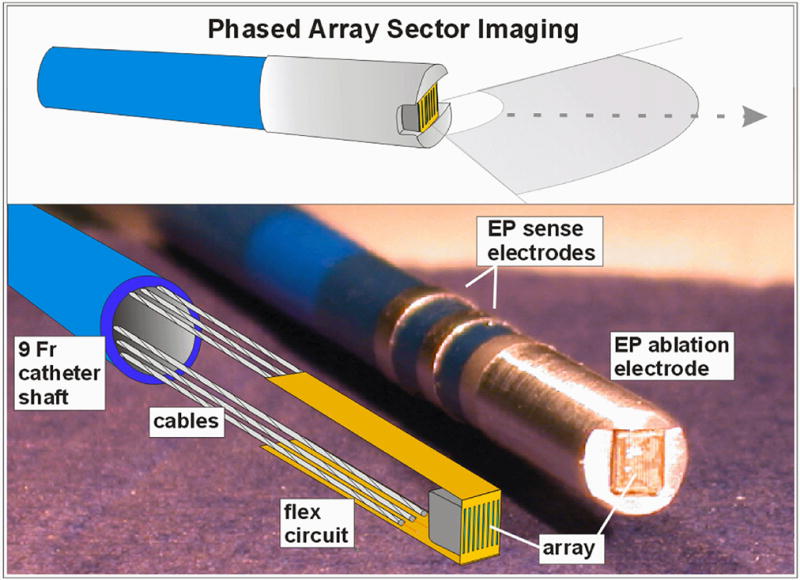
The 14MHz 24-element phased array forward-looking MicroLinear (ML) catheter tip region is shown. A completely equipped mechanical prototype is shown with its internal structures of the PZT array, flex circuit, and cabling in the lower panel at left.
Figure 2.
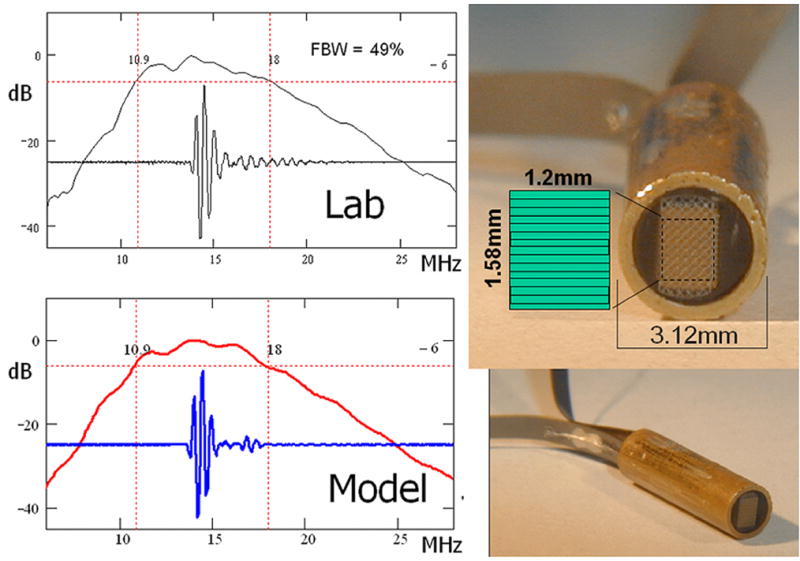
The second generation 14.4MHz MicroLinear piezoceramic 9 Fr subassembly is shown at right with the measured (top left) and estimated (bottom left) pulse echo performance. Fifty percent FBW was achieved. The array aperture of only 1.2mm by 1.58 mm is represented at the top right with the element layout as indicated.
Table 1.
PZT and cMUT Acoustic Array Design Parameters
| Design Parameter | Acoustic Array Design Type | ||
|---|---|---|---|
| Piezoceramic |
MEMS Silicon |
||
| Transducer Type | 2–2 composite PZT | cMUT Disk, or Rectangle | |
| Generation | Generation 1 | Generation 2 | Prototype |
| Catheter Size | 15F/10.2F | 9F | (in catheter assembly) |
| Transducer placement on flex circuit bend radius | inside | inside | outside |
| Array elements | 24 | 24 | 24 |
| Center Frequency (MHz) | 14 | 14 | 14 |
| Array pitch (mm) | 0.065 | 0.065 | 0.065 |
| Element Elevation (mm) | 1.2 | 1.2 | 1.2 |
The ML array construction is simple due to its very small size. With regards to the piezoceramic array, the flex circuit itself and a single thin parylene layer serve as the effective acoustic matching layers. The piezoceramic array is designed as a 2–2 composite structure using a high dielectric ceramic (L155N, TFT Corp., Tokyo, Japan) which has proved more reliable during fine dicing than the TRS-HK1 (TRS Technologies, State College PA) which had been used previously in the larger pitch HockeyStick array. The core ML array design is based on a stacked structure where one piezoceramic “layer” in the 2-2 PZT composite defines a single element prior to bonding the array to the flex circuit. The composite is 112 microns thick with 50 μm wide piezoceramic “stacked” elements and 15 microns epoxy filled kerfs. The front-side materials are: a 25 microns thick polyimide flex with 4.5 microns metal traces that make an electrical contact by compression through the bonding epoxy with the 2–2 composite structure, and a parylene layer at 10 microns thickness to serve as an insulating outer layer that prevents the flex circuit outside (ground shield) metal from touching biological tissue. The backing is a cast-on electrically conductive reference electrode side which is E-solder 3022 (Von Roll Isola, New Haven, CT) at approximately 1 millimeter in thickness. The ML array flex circuit assembly places the active signal wiring on the inside flex bend where solder connections to the internal coax cabling are made along with the ground wire connecting the piezoceramic grounded “backside” connection in a similar way as the HockeyStick array. This straightforward connection scheme allows for direct integration with the Vivid7 Dimension (GE VingMed Ultrasound, Horten, Norway) imaging system. The ML array is optimized for noisy catheter lab environments by utilizing a thin (3 microns) cross-hatch matrix metal ground shield on the entire outside bend surface of the flex circuit. Through hole vias are used in the flex circuit to join the outer metal shield to the inside flex circuit surface coax bond pad region.
The first-generation ML arrays were fabricated with 9 Fr catheter shafts and large 15 Fr (5mm) tip enclosures. This was done to avoid trace breaking and stress damage of the piezoceramic array after bending of the flex circuit following early assembly attempts. Improved assembly handling techniques resulted in a reduction in the flex bend radius which allowed smaller core assemblies. The original ML flex circuit was quite short at 13.6 mm; the second generation design has been extended to 120mm to augment the ML catheter tip flexibility by eliminating the relatively stiff set of 24 microcoax cables in distal tip region. The new longer flex circuit construction includes solder mask protection of the electrical traces in the long flex sections to maintain electrical trace isolation during the assembly. The second-generation ML arrays fit well within a 9 Fr distal tip construction. Thus far, five second-generation ML array assemblies have been fabricated and tested and are currently being integrated with 9 Fr catheter shafts (Figure 2).
Simulation and Bench Testing of the ML Array Designs
The first-generation ML catheter arrays showed only modest fractional bandwidth (FBW) performance at 25%, which was due to both poor mechanical bond lines in the array stack and unoptimized parylene thickness. Use of the KLM (35) acoustic transducer model revealed that the parylene layer, while needed for electrical isolation with biological tissue, is undesirable in this design for thicknesses beyond a few microns. An optimized parylene thickness of 10 microns was elected to achieve complete coverage without pinhole problems, and with only a 0.6dB loss in signal sensitivity and a 7% loss in maximum design bandwidth. With improved assembly techniques and optimization of the rudimentary matching layer, the second-generation devices have shown FBW performance in the 50% range. Array performance simulations agreed well with these new devices, as shown in Figure 2. Two-way pulse echo data from a flat X-cut quartz reflector at 3.75mm from the array in water were collected using a standard pulse generator (Panametrics 5900PR, 2μJ energy) and a fast sampling oscilloscope (LeCroy LC534, 500MS/sec). A direct image comparison with a commercial 10MHz phased array sector probe with elevation focusing was made to confirm that imaging parameters were working well on a Vivid7 commercial imaging system (Figure 3).
Figure 3.
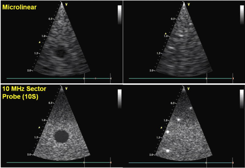
Phantom image test comparison with a commercial probe. The 14MHz 24 element Microlinear catheter array (top) with its limited aperture compares reasonably well to the much larger aperture neonatal probe, the Vingmed 10S (GE VingMed Ultrasound, Horten, Norway) (bottom), which is a 10MHz high frequency phased array equipped with 64 elements. Both arrays are tested here on the Vingmed Vivid 7 imaging system.
Pig Experiments
The prototype ML array was used in studies of four adult (34–55 kg) pigs, in three of which imaging was performed from the right atrium and the right ventricle to study ablation procedures performed in right-sided locations. In the fourth animal, the catheter was inserted into the right ventricle only, close to the septum for visualizing ablation on the left septal surface.
Closed-chest pigs were studied under general anesthesia with 2% isoflurane and mechanical ventilation. EKG, body temperature, and oxygen saturation were monitored; femoral arteries and veins as well as jugular veins were exposed by surgical incision, in preparation for catheter insertion. The Animal Care Committees of OHSU and UCLA approved the scientific methods and the animal treatment procedures.
In vivo placements of a radiofrequency ablation (RFA) devices were guided by visualization from the ML probe; in one particular case, a small, integrated ablation wire deployed directly from the tip an experimental combination ML catheter was tracked by the ML catheter (Figure 4b) during attempts at tissue ablation. Catheter ablations were otherwise performed using a Livewire catheter, 4 mm tip (St. Jude Medical Inc., Minnetonka, Minn.) at four locations in the isthmus area, or the right ventricle in three of the pigs, and in three locations in the left ventricle in the fourth pig. Ablation was accomplished with a Stockert RF generator (Biosense Webster, Diamond Bar, Calif.). The target temperature was 55°–70°C and the duration of delivery 60 seconds, with a power of 50W.
Figure 4.
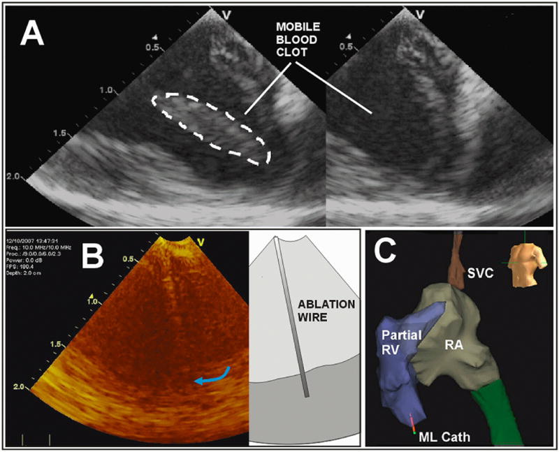
The ML in-vivo imaging image quality is demonstrated in A with a display depth of 2cm. A special ablation wire is tracked in B, and the ML catheter tip 3D spatial position in the apical region of the RV is tracked dynamically in panel C with a partially completed volumetric map of the right side of the pig heart with the use of the NavX electroanatomical mapping system; note the ML catheter tip shown near the RV apex at the bottom left in C.
Imaging characteristics, as well as interrogation for changes of strain mechanics, were accomplished using tissue Doppler strain imaging mode with the ML catheter operated with a Vivid7 Dimension at a transducer frequency of 12 MHz. High frame rate (120 frames per second) greyscale images were also obtained and processed with a 2D strain program for detecting alterations of cardiac mechanics associated with ablation in EchoPac software (GE Vingmed Ultrasound AS), processed off line.
RESULTS
Ablation Imaging
Along with a total imaging depth of field of at least 2.5 cm, the steerability and the forward-looking nature of this catheter made it easy to bring it into proximity with the ablation catheter and set up for imaging ablation within one minute of attempted manipulation and only two or three short fluoroscopic bursts. There was little difference in the ability to visualize ablation from the right ventricle and within the right ventricle compared to visualization from the right ventricle of septal ablation on the left ventricular side. Figure 4a shows the general near field image quality of a mobile blood clot, the imaging of a special ablation wire which had been specially integrated in a side channel of one of the ML designs, and as well a NavX electroanatomical mapping result of the right heart with the ML clearly delineated near the apex of the right ventricle.
Ablation could be localized by a) tissue brightening along with the expected bubble formation from gas evolution (36) during tissue heating as illustrated in Figure 5, as well as by b) significant diminution of regional strain both for 2D strain computation and for strain rate determined online using tissue Doppler imaging as shown in Figure 6. The RF shielding of the ML imaging catheter was adequate in the sense that any minor RF noise interferences observed in the ultrasound images were localized to a brightening and reverberation in the far field which were generally away from near field views of ablations sites. In addition, imaging noise from ablation activity was minimal in the ML forward-looking catheter as compared to our side-looking (unshielded) HockeyStick design.
Figure 5.
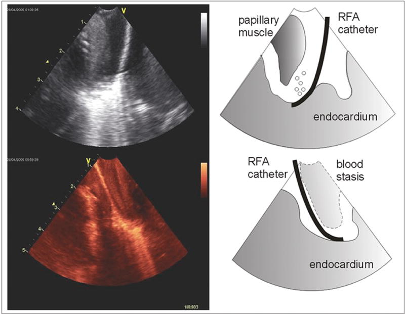
Ablation visualized in the RV apex. From the onset of the activation of the RF ablation energy, the tip of the ablation catheter generates a brightened tissue signal created by tissue gas bubbles evolution.
Figure 6.
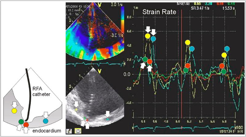
Strain rate imaging following ablation. The cup shaped tissue depression beneath the flexible ablation tip has decreased strain, as shown by the time course of the red and green traces. The yellow and turquoise traces (with “down” arrows) show noticeably greater peak strain rate than the red and green traces (with peaks at the “up” arrows). The diminution in strain rate of this region was still present after the ablation catheter had moved away.
Ablation sites in three of the four pigs were verified by pathologic examination after the animals were terminated (Figure 7).
Figure 7.
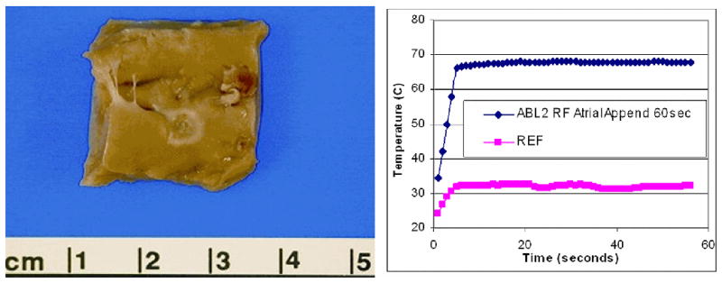
An ablation lesion created on the endocardial surface of the right atrial appendage is shown at the left, with the ablation site temperature plot at right. To confirm tissue temperatures during ablation a pair of 0.5mm fluoroptic (Luxtron, Santa Clara, Calif.) temperature probes were placed within the myocardium.
DISCUSSION
We have previously reported on the first of three devices built in this program, a piezoelectric ceramic side-looking 9F catheter called the Hockeystick. In concept, its design as a side-looking imaging device was not unlike the AcuNav catheter, although efforts to produce it preceded the introduction of that product. Both our side-looking phased array intracardiac imaging catheter and the forward-looking ML catheter have satisfactorily agile handling, built with the inherent directional steerability of EP catheters. The EP-enabled capability has permitted the recording of intracardiac electrical potentials, although not under visualization of the array, since the EP electrodes were mounted at the tip and behind the array. These enabling electrodes however, used in both the Hockeystick and the ML catheters, have allowed a very straight forward integration with the NavX mapping system for 3D electroanatomical spatial localization.
A key limitation in the optimal integration of the NavX and the side-looking device has been the necessity of preparing a specially segmented electrode on the catheter shaft to permit a continuous electroanatomical computation of the shaft’s angular position which would produce the 3D geometric position of the array’s image plane. Plans are underway for this extended NavX integration in both the ML and the HockeyStick catheter designs, which will be particularly valuable in the localization of the ML image plane as a small field-of-view device.
The MicroLinear represents the first very high frequency near field optimized forward-looking intracardiac device which operates without special software on a standard commercial imaging system. It incorporates the same dynamic steerability that was designed into the side viewing Hockeystick, which aids navigation. Additional planned steps in the evolution of this technology will include the completion of a thermally efficient cMUT array capable of delivering high intensity focused ultrasound for ablation, integrating imaging with therapy in the same device.
Acknowledgments
This research was supported by NHLBI Bioengineering Research Partnership grant R01 HL67647, “High frequency ultrasound arrays for cardiac imaging.” For the assembly and testing of prototypes, the authors gratefully acknowledge contributions of Ruibin Liu, and Jay Williams of the University of Southern California, and of Rick Kust and Hien Nguyen of Irvine Biomedical, Inc. Essential animal laboratory aid and experimental data management were provided by Gina Akopyan of UCLA, and by Simon Pranaitis of St. Jude Medical.
Abbreviations
- EP
electrophysiology
- ICE
intracardiac echocardiography
- Fr, or F
French size for catheters (3Fr=1mm)
- ML
microlinear
- IVUS
intravascular ultrasound
- AWG
American wire gauge
- ZIF
zero insertion force
- MEMS
microelectromechanical system
- cMUT
capacitive micromachined ultrasound transducer
- PZT
lead zirconate titanate
- KLM
Krimholtz-Leedom- Matthaei transmission line model
- FBW
fractional band width
- RFA
radiofrequency ablation
References
- 1.Lloyd-Jones DM, Wang TJ, Leip EP, et al. Lifetime risk for development of atrial fibrillation: the Framingham Heart Study. Circulation. 2004;110:1042–1046. doi: 10.1161/01.CIR.0000140263.20897.42. [DOI] [PubMed] [Google Scholar]
- 2.Cappato R, Calkins H, Chen SA, et al. Worldwide Survey on the Methods, Efficacy, and Safety of Catheter Ablation for Human Atrial Fibrillation. Circulation. 2005;111:1100–1105. doi: 10.1161/01.CIR.0000157153.30978.67. [DOI] [PubMed] [Google Scholar]
- 3.Drant SE, Klitzner TS, Shannon KM, Wetzel GT, Williams RG. Guidance of radiofrequency catheter ablation by transesophageal echocardiography in children with palliated single ventricle. Am J Cardiol. 1995;76:1311–1312. doi: 10.1016/s0002-9149(99)80364-6. [DOI] [PubMed] [Google Scholar]
- 4.Gorge G, Ge J, Baumgart D, von Birgelen C, Erbel R. In vivo tomographic assessment of the heart and blood vessels with intravascular ultrasound. Basic Res Cardiol. 1998;93:219–240. doi: 10.1007/s003950050090. [DOI] [PubMed] [Google Scholar]
- 5.Lai WW, Al-Khatib Y, Klitzner TS, et al. Biplanar transesophageal echocardiographic direction of radiofrequency catheter ablation in children and adolescents with the Wolff-Parkinson-White syndrome. Am J Cardiol. 1993;71:872–874. doi: 10.1016/0002-9149(93)90843-2. [DOI] [PubMed] [Google Scholar]
- 6.Lesh MD, Kalman JM, Karch MR. Use of intracardiac echocardiography during electrophysiologic evaluation and therapy of atrial arrhythmias. J Cardiovasc Electrophys. 1998;9:S40–S47. [PubMed] [Google Scholar]
- 7.Chu E, Fitzpatrick AP, Chin MC, Sudhir K, Yock PG, Lesh MD. Radiofrequency catheter ablation guided by intracardiac echocardiography. Circulation. 1994;89:1301–1305. doi: 10.1161/01.cir.89.3.1301. [DOI] [PubMed] [Google Scholar]
- 8.Shpun S, Gepstein L, Hayam G, Ben-Haim SA. Guidance of radiofrequency endocardial ablation with real-time three-dimensional magnetic navigation system. Circulation. 1997;96:2016–2021. doi: 10.1161/01.cir.96.6.2016. [DOI] [PubMed] [Google Scholar]
- 9.Kadish A, Hauck J, Pederson B, Beatty G, Gornick C. Mapping of atrial activation with a noncontact, multielectrode catheter in dogs. Circulation. 1999;99:1906–1913. doi: 10.1161/01.cir.99.14.1906. [DOI] [PubMed] [Google Scholar]
- 10.Gornick CC, Adler SW, Pederson B, Hauck J, Budd J, Schweitzer J. Validation of a new noncontact catheter system for electroanatomic mapping of left ventricular endocardium. Circulation. 1999;99:829–835. doi: 10.1161/01.cir.99.6.829. [DOI] [PubMed] [Google Scholar]
- 11.Schwartz SL, Pandian NG, Kusay BS, et al. Real-time intracardiac two dimensional echocardiography: An experimental study of in vivo feasibility, imaging planes and echocardiographic anatomy. Echocardiography. 1990;7:443–455. doi: 10.1111/j.1540-8175.1990.tb00385.x. [DOI] [PubMed] [Google Scholar]
- 12.Olgin JE, Kalman JM, Chin M, et al. Electrophysiological effects of long, linear atrial lesions placed under intracardiac ultrasound guidance. Circulation. 1997;96:2715–2721. doi: 10.1161/01.cir.96.8.2715. [DOI] [PubMed] [Google Scholar]
- 13.Hirshfeld J, Balter S, Brinker J, et al. ACCF/AHA/HRS/SCAI clinical competence statement on physician knowledge to optimize patient safety and image quality in fluoroscopically guided invasive cardiovascular procedures; A report of the American College of Cardiology Foundation/American Heart Association/American College of Physicians Task Force on Clinical Competence and Training. J Am Coll Cardiol. 2004;44:2259–2282. doi: 10.1016/j.jacc.2004.10.014. [DOI] [PubMed] [Google Scholar]
- 14.Dairywala I, Li P, Liu Z, et al. Catheter-based interventions guided solely by a new phased-array intracardiac imaging catheter: In vivo experimental studies. J Am Soc Echocardiogr. 2002;15:150–158. doi: 10.1067/mje.2002.115774. [DOI] [PubMed] [Google Scholar]
- 15.Packer D, Stevens C, Curley M, et al. Intracardiac phased-array imaging: Methods and initial clinical experience with high resolution, under blood visualization, initial experience with intracardiac phased-array ultrasound. J Am Coll Cardiol. 2002;39:509–516. doi: 10.1016/s0735-1097(01)01764-8. [DOI] [PubMed] [Google Scholar]
- 16.Ren J-F, Marchlinski F, Callans D, Herrmann H. Clinical use of AcuNav diagnostic ultrasound catheter imaging during left heart radiofrequency ablation and transcatheter closure procedures. J Am Soc Echocardiogr. 2002;15:1301–1308. doi: 10.1067/mje.2002.124646. [DOI] [PubMed] [Google Scholar]
- 17.Zong H, Lacomis JM, Schwartzman D. On the accuracy of CartoMerge for guiding posterior left atrial ablation in man. Heart Rhythm. 2007;4:595–602. doi: 10.1016/j.hrthm.2007.01.033. [DOI] [PubMed] [Google Scholar]
- 18.Daccarett M, Segerson NM, Gunther J, et al. Blinded correlation study of three-dimensional electro-anatomical image integration and phased array intra-cardiac echocardiography for left atrial mapping. Europace. 2007;9:923–926. doi: 10.1093/europace/eum192. [DOI] [PubMed] [Google Scholar]
- 19.Fahmy TS, Mlcochova H, Wazni OM, et al. Intracardiac echo-guided image integration: Optimizing strategies for registration. J Cardiovasc Electrophysiol. 2007;18:276–282. doi: 10.1111/j.1540-8167.2007.00727.x. [DOI] [PubMed] [Google Scholar]
- 20.Martinek M, Nesser HJ, Aichinger J, Boehm G, Purerfellner H. Impact of integration of multislice computed tomography imaging into three-dimensional electroanatomic mapping in clinical outcomes, safety, and efficacy using radiofrequency ablation for atrial fibrillation. PACE. 2007;30:1215–1223. doi: 10.1111/j.1540-8159.2007.00843.x. [DOI] [PubMed] [Google Scholar]
- 21.Gepstein L, Hayam G, Ben-Haim S. A novel method for nonfluoroscopic catheter-based electroanatomical mapping of the heart, in vitro and in vivo accuracy results. Circulation. 1997;95:1611–1622. doi: 10.1161/01.cir.95.6.1611. [DOI] [PubMed] [Google Scholar]
- 22.Wittkampf F, Wever E, Derksen R, et al. LocaLisa: New technique for real-time 3-dimensional localization of regular intracardiac electrodes. Circulation. 1999;99:1312–1317. doi: 10.1161/01.cir.99.10.1312. [DOI] [PubMed] [Google Scholar]
- 23.Earley M, Showkathali R, Alzetani M, et al. Radiofrequency ablation of arrhythmias guided by non-fluoroscopic catheter location: A prospective randomized trial. Eur Heart J. 2006;27:1223–1229. doi: 10.1093/eurheartj/ehi834. [DOI] [PubMed] [Google Scholar]
- 24.Kennedy J, ter Haar G, Cranston D. High intensity focused ultrasound: surgery of the future? Brit J Radiol. 2003;76:590–599. doi: 10.1259/bjr/17150274. [DOI] [PubMed] [Google Scholar]
- 25.Lubbers J, Hekkenberg R, Bezemer R. Time to threshold (TT): A safety parameter for heating by diagnostic ultrasound. Ultrasound Med Biol. 2003;29:755–764. doi: 10.1016/s0301-5629(02)00790-1. [DOI] [PubMed] [Google Scholar]
- 26.Pham PP, Balaji S, Shen I, Ungerleider R, Li XK, Sahn DJ. Impact of conventional versus biventricular pacing on hemodynamics and tissue Doppler imaging indexes of resynchronization postoperatively in children with congenital heart disease. J Am Coll Cardiol. 2005;46:2284–2289. doi: 10.1016/j.jacc.2005.08.036. [DOI] [PubMed] [Google Scholar]
- 27.Li XK, Pemberton J, Thomenius K, et al. Development of an EP enabled intracardiac ultrasound catheter integrated with NavX 3D electrofield mapping for guiding cardiac EP interventions: Experimental studies. J Ultrasound Med. 2007;26:1565–1574. doi: 10.7863/jum.2007.26.11.1565. [DOI] [PMC free article] [PubMed] [Google Scholar]
- 28.Stephens D, Cannata J, Liu R, et al. The acoustic lens design and in vivo use of a multifunctional catheter combining intracardiac ultrasound imaging and electrophysiology sensing. IEEE Transactions on Ultrasonics, Ferroelectrics, and Frequency Control. 2008;55:602–618. doi: 10.1109/TUFFC.2008.685. [DOI] [PMC free article] [PubMed] [Google Scholar]
- 29.Smith SW, Light ED, Wolf PD. Feasibility study of in-vivo real-time 3D intracardiac ultrasound. J Am Coll Cardiol. 1999;33:405A . [abstr] [Google Scholar]
- 30.Back M, Kopchok G, White R, et al. Forward-looking intravascular ultrasonography: In vitro imaging of normal and atherosclerotic human arteries. American Surgeon. 1994;60:738–743. [PubMed] [Google Scholar]
- 31.Gatzoulis L, Watson RJ, Jordon LB, et al. Three-dimensional forward-viewing intravascular ultrasound imaging of human arteries in vitro. Ultrasound Med Biol. 2001;27:969–982. doi: 10.1016/s0301-5629(01)00371-4. [DOI] [PubMed] [Google Scholar]
- 32.Light ED, Idriss SF, Wolf PD, Smith SW. Real time three dimensional intracardiac echocardiography. Ultrasound Med Biol. 2001;27:1177–1183. doi: 10.1016/s0301-5629(01)00421-5. [DOI] [PubMed] [Google Scholar]
- 33.Lee W, Smith S. Miniaturized catheter 2D for real-time 3D intracardiac echocardiography. IEEE Trans Ultrason Ferroelec Freq Contr. 2004;51:1334–1346. doi: 10.1109/tuffc.2004.1350962. [DOI] [PubMed] [Google Scholar]
- 34.Nikoozadeh A, Wygant I, Lin D, et al. Fully integrated cMUT-based forward-looking intracardiac imaging probe for electrophysiology. Proceedings of IEEE International Ultrasonics Symposium; 2007. pp. 900–903. [Google Scholar]
- 35.Krimholtz R, Leedom D, Matthaei G. New equivalent circuit for elementary piezoelectric transducers. Electron Lett. 1970;6:398–399. [Google Scholar]
- 36.Marrouche NF, Natale A. Monitoring pulmonary vein isolation using phased array intracardiac echocardiography in a patient with atrial fibrillation. Electromedica. 2002 [Google Scholar]