Abstract
It has long been recognized that cationic nanoparticles induce cell membrane permeability. Recently, it has been found that cationic nanoparticles induce the formation and/or growth of nanoscale holes in supported lipid bilayers. In this paper we show that non-cytotoxic concentrations of cationic nanoparticles induce 30–2000 pA currents in 293A and KB cells, consistent with a nanoscale defect such as a single hole or group of holes in the cell membrane ranging from 1 to 350 nm2 in total area. Other forms of nanoscale defects, including the nanoparticle porating agents adsorbing onto or intercalating into the lipid bilayer are also consistent; although the size of the defect must increase to account for any reduction in ion conduction, as compared to a water channel. An individual defect forming event takes 1 – 100 ms, while membrane resealing may occur over tens of seconds. Patch-clamp data provide direct evidence for the formation of nanoscale defects in living cell membranes. The cationic polymer data are compared and contrasted with patch-clamp data obtained for AMO-3, a small molecule that is proposed to make well-defined 3.4 nm holes in lipid bilayers. Here, we observe data that are consistent with AMO-3 making ~3 nm holes in living cell membranes.
Introduction
The interaction of synthetic nanoparticles and cells is a topic of growing interest. There is significant evidence that exposure of cells to many types of nanoparticles results in enhanced porosity of the cellular membrane with implications for drug and gene delivery as well for both acute and chronic toxicity.1–7 Researchers have used cell culture assays to examine increased leakage of cytosolic components out of, or extracellular dyes into, cells upon exposure to nanoparticles. Concentrations of polymeric nanoparticles that yield millimolar charge concentrations are acutely cytotoxic and lead to cell lysis.1,2,5 It has also been discovered that cells exposed to non-cytotoxic concentrations of polycationic nanoparticles for one hour leak cytosolic LDH(lactate dehydrogenase) into the supernatant and that dyes such as FDA(flourescein diacetate) are able to move through the previously impermeable cellular membrane.1,2 Complementing these cell-level studies, atomic force microscopy (AFM) experiments have examined the formation of nanoscale holes in supported lipid bilayers, model membranes, caused by nanoparticles.3,8,9 Theoretical studies of these hole formation events have shown that these processes are thermodynamically feasible.10 This has lead to the hypothesis that the cell membrane leakage observed at non-cytotoxic concentrations arises from the nanoscale holes induced in the cell plasma membrane.1,2,4 However, no measurement of individual nanoscale hole forming events induced by cationic nanoparticles on living cell membranes, and or the characterization of the time course of the events, has been reported.
In this paper we report data demonstrating that exposure of live cells to nanoparticles results in the formation of nanoscale defects. Specifically, whole-cell patch-clamp experiments are used to examine cell membrane porosity via measurement of the electrical conductance of 293A (human embryonic kidney) and KB (human epidermoid carcinoma) cells before and after exposure to nanoparticles. The experimental results show: a) exposure of cells to non-cytotoxic levels of cationic nanoparticles results in the formation of defects that enhance conductance through the cellular membrane, b) these defects can “recover” over time allowing a decrease in transmembrane conductance toward its original value, and c) that the size scale of these defects is comparable to that observed in model membrane studies by AFM and large enough to explain the observed diffusion of macromolecules through the cellular membrane.1,2 In addition, direct evidence of nanoscale hole formation induced by an amphiphillic phenylene ethynylene antimicrobial oligomer (AMO-3 )11–13 in living cell membranes is reported and compared and contrasted with the results obtained for the polycationic polymer nanoparticles.
Poly(ethyleneimine) (PEI), poly-L-lysine (PLL), generations 5 and 7 poly(amidoamine) (PAMAM) dendrimers, poly(vinylalcohol) (PVA), and poly(ethyleneglycol) (PEG) were selected for this study because they represent an important group of biomedical polymers being developed for drug and gene delivery applications. Additionally, cell-level porosity assays and AFM studies have been performed with them.1,2 As a contrast to these macromolecular nanoparticles, experiments were also performed with an antimicrobial small molecule with an m-phenylene ethynylene backbone (AMO-3).11–13 At the concentrations used, 1–3 of these small molecules are believed to act cooperatively to form ~3.4 nm regular pores in model membrane systems.12,13 Full details of all materials employed for these studies, as well as the patch-clamp method are provided in Experimental Procedures.
Results
Current-Voltage Relationships
Current-voltage (I-V) relationships for 293A cells before and after exposure to the cationic (PEI, PLL, G5-NH2, G7-NH2) and neutral (PVA, PEG) nanoparticles are shown in Figure 1. The molecular weight and polydispersity index of the cationic polymers is provided in Table S1. The conductance (slope of the I-V relationship) after 20 min exposure to the cationic polymers is in the range of 80–120 nS, an increase of ~50 times as compared with control cells. Figures S1 and S2 show the more detailed time evolution of the I-V characteristics for a single KB cell after exposure to 6 μg/mL PEI and 30 μg/ml AMO-3 solution respectively. The concentration for each nanoparticle was selected to obtain roughly equivalent membrane disruption effects as measured by the extent of LDH leakage.1,2 Exposure to neutral PVA and PEG did not result in an increase in conductance beyond the background value of 2 nS, see inset in Figure 1. Two other important characteristics of the IV relationships are the effect on cell membrane resting potential and the linearity. After exposure to PEI, PLL, G5-NH2 or G7-NH2, the increase in conductance coincided with an increase in the cell membrane potential from ~ −20 mV to ~ 0 mV, seen in figure S1. This indicates that the induced conductance is not cation specific (primarily Na+ extracellularly and K+ intracellularly). Additionally, the linearity of the I-V relationships, i.e. the absence of rectification, shows that Na+, K+ and likely Cl− ions are the major carriers of the current.
Figure 1.
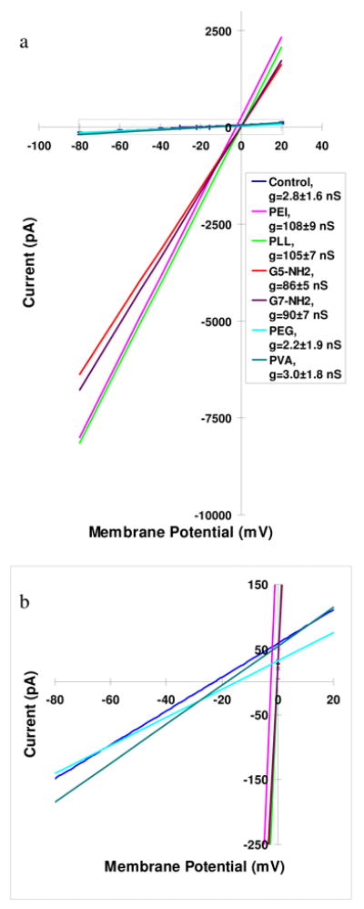
(a) Current-voltage relationships (average of three for each condition) for 293A cells exposed to polymer nanoparticle solutions. Membrane potential was ramped from −80 to 20 mV in 2 sec. After stable recordings were obtained (usually ~5 minutes), external solutions (Modified Tyrode, pH 7.4) containing the nanoparticles were applied to the cells. Slopes of the curves represent the average conductance (g, shown in inset) after 20 min application of polycationic solutions and charge neutral polymer solutions. Polycationic solutions contained 6 μg/mL PEI, 13 μg/mL PLL, 12 μg/mL G5-NH2, and 24 μg/mL G7-NH2 (pink, bright green, red, and purple, respectively); upon application the reversal potentials of the cells moved toward 0 mV, and the conductance of the cells dramatically increased to 80 – 120 nS. Charge neutral polymer solutions contained 6 μg/mL PEG, and 6 μg/mL PVA (turquoise and dark green, respectively). (b) Expanded view of dash box in (a). Nonexposed control cells (dark blue line) show a conductance of 2.8±1.6 nS and the reversal potential of − 22.9±7.2 mV (n= 20). The conductance and reversal potential of the cells after 20 min application of charge neutral polymer solutions (PVA, green; PEG, light blue; average of three) remain statistically the same as the control cells. (Note the membrane potentials are not corrected for voltage errors due to pipette series resistance, see supplemental information)
The implications of these results are two-fold. First, the absence of rectification in the I-V data indicate that the nanoparticles do not serve as the primary charge carriers. Second, the mechanism of endocytosis itself precludes it as a process that would result in an increase in current, even when positively charged nanoparticles are involved. Specifically, during endocytosis bulk ions from solution and surface charge neutralization between the lipid head groups and the nanoparticle would combine to form an electrically neutral vesicle that would not contribute to any net current flow. Instead the data indicate that exposure to these nanoparticles results in a breach of the cell membrane that opens the interior of the cell to the extracellular medium through holes that are not ion specific.
Current-Time Traces
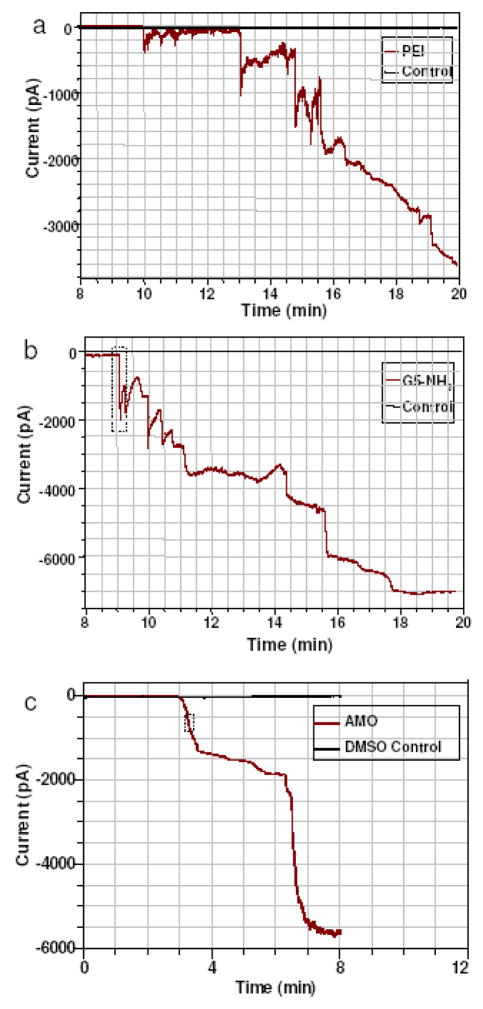
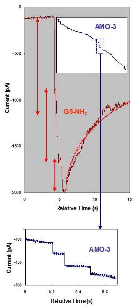
Figure 2 shows the gross time evolution of the increase in current after exposure to PEI, G5-NH2, and AMO-3. As an exemplar, the details of the onset and partial recovery of a few events is shown in Figure 3. These changes in conductance are identified as individual defect formation events because they are discrete, rapid (1–100 ms rise time) increases in current flow that are followed, in the case of the polymers, by a slower recovery (1 – 10 secs). After recording a number of current-time traces it is possible to construct a frequency histogram of current steps with a particular magnitude.
Figure 2.
Current-time recordings of 293A cells exposed to (a) 6 μg/mL PEI, (b) 12 μg/mL G5-NH2, and (c) 30 μg/mL AMO-3. Abscissa represents time after application of nanoparticles. The delay before onset of current events is primarily due to the transit time for nanoparticles to reach the cell (see Methods).
Figure 3.
Enlargement of the dotted-line insets in Figure 2(b) and (c) with the abscissa representing the relative time after application of nanoparticles. The current trace for G5- NH2 shows three individual current steps labelled with red arrows and an exponential fit of a current recovery with a dotted red line. The inset panel shows the current trace for application of AMO-3. The blue dotted box inset, enlarged in the bottom panel, shows four individual current steps and the lack of their recovery.
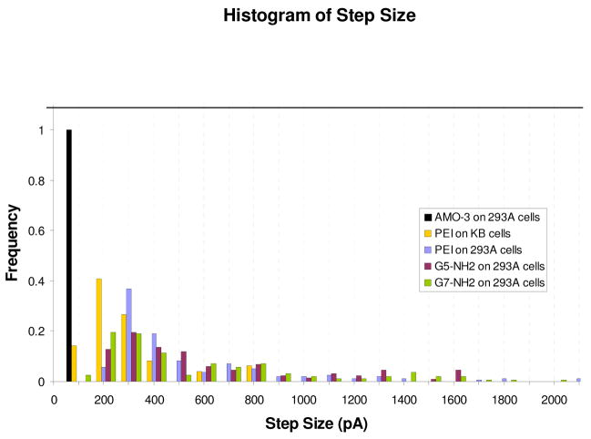
Using 42 current-time traces for PEI, G5, G7 and AMO-3, 614 current steps were analyzed and the corresponding histograms presented in Figure 4. The mean current step sizes for PEI, G5 and G7 are 490 ± 401, 770 ± 782 and 921± 1192 pA respectively. The extremely large standard deviations arise from the current distributions being non-gaussian, each possessing an asymmetric long tail toward large magnitude steps. In contrast, the current steps observed with exposure to AMO-3 are smaller in magnitude and much more narrowly distributed, all within a single bin. It should be noted that the defects reported in Figure 4 are the initial set of forming events, current < 5 nA, observed after exposure to the nanoparticles. As the experiment progresses nanoparticles are continuously being added to the extracellular solution, so that after some time the occurrence of defect formation and membrane healing begin to overlap to such a degree that it becomes impossible to identify individual disruption events.
Figure 4.
Normalized histogram of current step distributions for 293A cells exposed to PEI, G5-NH2, G7-NH2, and AMO-3, and for KB cells exposed to PEI, with 100 pA bin size. The histograms were formed from n = 8, 12, 13, 5, and 4 individual cell recordings, respectively. The scale for hole diameters (top axis) was obtained from Equations (1) and (2) in Discussion section.
In previous studies, the recovery of cell integrity was monitored by enzyme leakage assays.1 The results showed that the cationic polymer nanoparticle-induced porosity was eliminated after removal of the particles for 2 hours. Using the patch-clamp technique allows much better time resolution and many of the recorded current events showed immediate signs of recovery after the initial increase in current flow. However, unlike the rapid onset of current, which happens in milliseconds, recovery takes a period of 10’s of seconds to occur. Approximately 60% of the events for all three types of cationic polymer nanoparticles showed an immediate recovery of 20–50% in current flow. By fitting each of these recovery events to an exponential, a time constant could be obtained to quantify their time evolution. A histogram of these values is shown in Figure 5. The porosity produced by exposure to PEI recovers the fastest and exhibits a mean time constant of 5 ±2 (n =26) seconds, which is consistent with PEI forming the largest fraction of small holes. The mean time constants for recovery are 12 ±4 (n =21) and 26 ±12 (n =28) seconds for G5 and G7, respectively. Student’s t-test shows that the mean values of the recovery time constants are different between PEI, G5-NH2, and G7-NH2 at the 90% confidence level. Finally, and in distinct contrast to the polycationic polymer nanoparticles, it is important to note that the current steps produced by the AMO-3 do not show any recovery (Figure 3b).
Figure 5.
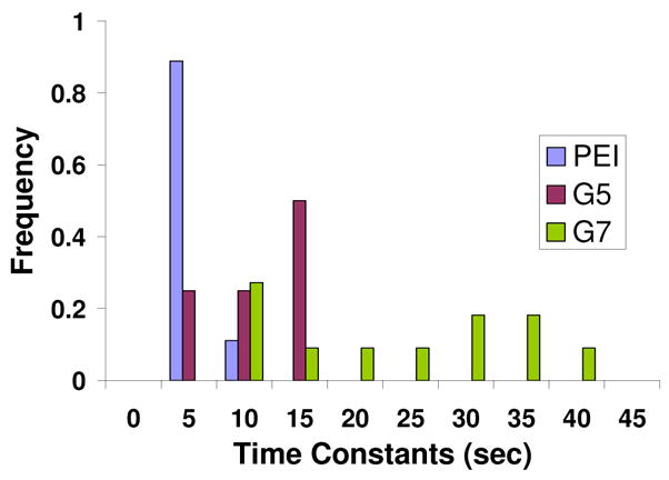
Time constants of current recoveries for 293A cells exposed to PEI, G5-NH2, and G7-NH2. The exponential fitting of time constants is as illustrated in Figure 3 (dotted red line). Cells exposed to AMO-3 did not show any recovery.
Discussion
Previous reports from our group used data from AFM studies to propose a model in which the positively charged dendrimeric nanoparticles remove lipid, leading to the formation of a nanoparticle-filled vesicle.9 The number of lipids required to form this vesicle is ~1400 for a G7-NH2 dendrimer. This leads to expected membrane defects of 23 nm diameter which is in good agreement with AFM images of holes formed in supported lipid bilayers after exposure to G7 dendrimers.8 Can the increases in conductance found in the patch-clamp experiments be used to determine the size of the defects in the cellular membrane?
To estimate the diameter of the defects that are formed when cells are exposed to nanoparticles a model for the conductance of a membrane pore is used. Following work measuring ion channel conductance in membranes, the diameter of nanoparticle-induced holes is calculated based on the magnitude of the conductance step, gstep, using a well-known equation for channel conductance:14,15
| (1) |
where Rstep is the resistance of the hole (based on the conductance of the current step), r is the radius of the hole, l is the hole length and ρ is the resistivity of the solution. The thickness of the membrane, i.e. length of the hole, is approximately 7 nm and the resistivity of the physiological solution is about 50 Ωcm. Using expression (1) and
| (2) |
where ΔIstep is the magnitude of the current step, Em is the holding potential and Erev is the reversal potential (considered 0 mV from the I-V relationships), it is possible to relate the experimentally measured current step to an estimate of the diameter of the hole needed to produce that change. These estimated values for the diameter of the hole formed by the nanoparticles are shown on the upper axis over the histograms in Figure 4. The estimated error for this axis is ±50% with the largest uncertainties due to the assumed resistivity of the bathing solution (~50 Ωcm) and the voltage drop on the patch-clamp pipette. (See Supplemental Information for error estimates.)
Viewing the data presented in Fig 4, it is evident that the PEI produces a larger fraction of events with a small current increase and calculated diameters of less than 4 nm. This correlates well with the fact that AFM studies of smaller dendrimers, G3 and G5, showed that they eroded material at the edges of defects whereas G7 had the capability to form larger holes on seemingly undefected lipid. Given the significant polydispersity of PEI, including a large fraction of low molecular weight material, finding numerous small events is not unexpected. The fact that G7 shows the same number of small current events (4–6 nm) as G5 suggests that the structural features of the cell membrane may play a dominate role in determining the magnitude of the current events. However, the recovery times for the defects caused by G7 were larger than those for PEI and G5. This could indicate that G7 dendrimers interact more strongly with the membrane defects increasing their stability.
It is interesting to note that the diameter of a circular section of membrane needed for the formation of a lipid vesicle with a G7 core is in the range of 13 – 16 nm. This structure has been postulated as a possible product that is formed when leptosomes and G7 dendrimers interact. Similar vesicle formation for G5 dendrimers is thought to require at least four dendrimers at the core. The long tail on the G7 distribution extends out to these diameters and beyond. It is possible that the origin for the highly asymmetric distribution is the formation of such dendrimer-vesicle complexes.8
Turning to the AMO-3 data presented in Figures 2, 3 and 4 there is a strong contrast between it and the results for the polymer nanoparticles. The most obvious difference is in the magnitude of the individual current steps: they are much smaller with a mean of 34±12 pA. Using the transport model described above, the area of the pore formed by the AMO-3 molecules is calculated to be ~2 nm in diameter. The second notable feature is the narrow size distribution. Lastly, unlike with the polymer nanoparticles, no recovery of the current is observed for the AMO-3 data.
These contrasts between the behaviour of the polymer nanoparticles and AMO-3 can be examined in light of recent studies of the structure of the pores generated by AMOs. Wong et. al report SAXS experiments that show lipid bilayers developing an inverted hexagon structure upon exposure to AMO-3.13 The structure is caused by the amphiphilic molecules inserting into the lipids and stabilizing the mosaic of pores. Analysis of diffraction data yields a lattice of 3.4 nm diameter pores with several AMO molecules associated with each individual hole.12 The AMO-3 patch-clamp data, including the magnitude and homogeneity of the measured current steps and the lack of recovery, are consistent with the structural proposal based upon the diffraction data (vida infra).
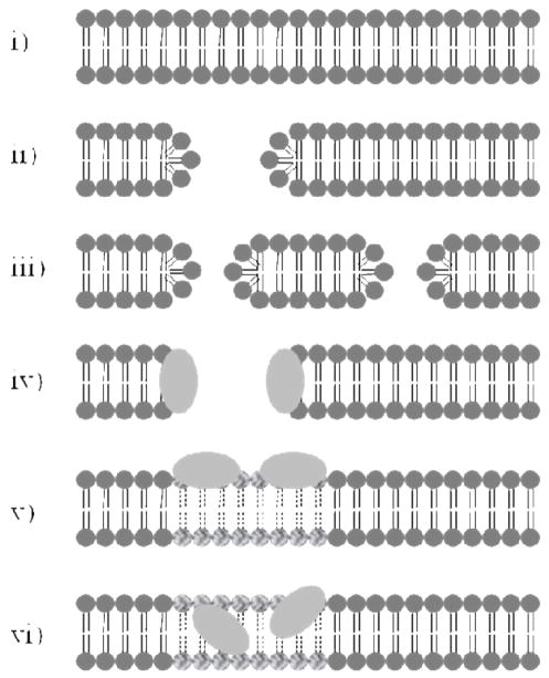
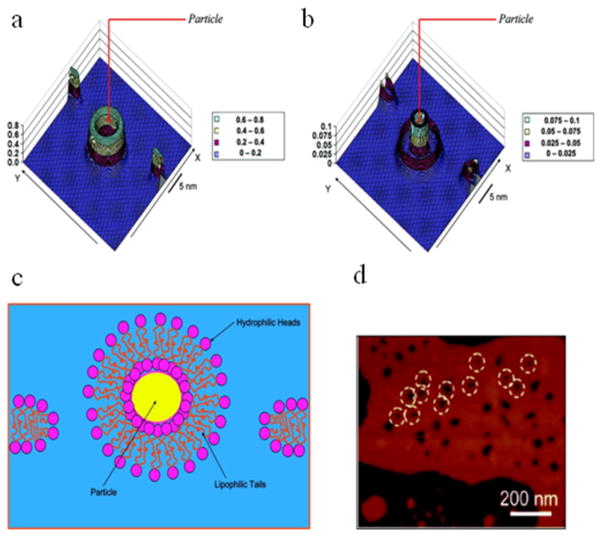
The formation of a nanoscale hole in the cell membrane, filled with water and ions, provides the lower bound for the size of the disruptive events causing the ion permeability measured in this study. A hole or pore of this type is illustrated schematically in Figure 6(ii). Note that using the current measured by whole-cell patch-clamp we cannot distinguish a single hole (ii) from two holes that sum to the same area (iii), or for that matter any number of holes with areas that allow a summing of ion conductance. The hypothesis of nanoscale holes of this type is also supported by AFM measurements on supported lipid bilayers, where holes of this size were directly imaged, and simulations as highlighted in Figure 7.8,10 An important variation to consider is a nanoscale hole that is coated with the porating agent as illustrated in schematic model (iv). This may serve to stabilize the hole and would likely affect the current recovery times (Figure 5). Such models have substantial precedence in the literature for AMOs as illustrated in Figure 8. As mentioned above, our data are in excellent agreement with these proposals.12,13 A coated pore has also been proposed for PAMAM dendrimers as shown in Figure 9B.16 Intercalation models such as (vi) have also been proposed for PAMAM dendrimers as shown in Figure 9A.17 Simulation models of dendrimers and PLL also show membrane binding and lipid disruption as illustrated in model (v).16–21 Note that for models (v) and (vi) of the nanoscale defects, the ion conduction would be expected to be substantially reduced as compared to nanoscale hole model (ii). Thus for models (v) and (vi), the size of the nanoscale defect implied by the currents shown in Figures 2–4 would be larger than the predicted sized of the simple holes in which lipid and other membrane components, as well as the porating species themselves, do not occlude the hole.
Figure 6.
i) Schematic of unperturbed membrane. Models ii-vi represent various forms of nanocale membrane defects consistent with the ionic currents measured in this work: ii) nanoscale hole in membrane iii) two nanoscale holes in membrane with same area as case (i) above are indistinguishable when only considering current flow iv) nanoscale hole supported by porating agent such as AMO or cationic polymer v) membrane disrupted by surfacing binding, affected lipid head groups and tails are highlighted vi) membrane disrupted by intercalation.
Figure 7.
Detailed proposed model of PAMAM dendrimer causing hole formation analogous to schematic models (ii) and (iii). (A) Simulated density map of the lipophilic part of the bilayer. (B) Simulated density map of the hydrophilic (headgroup) part of the bilayer. X-axis is normal to the bilayer plane. (C) Sketch demonstrating the formation of a nanoparticle-bilayer complex and corresponding breakage of the original membrane. (D) AFM pictures of lipid bilayers with holes made by charged PAMAM dendrimers. Particle radius Rp = 2.4 nm. Reprinted with permission from reference 10.
Figure 8.
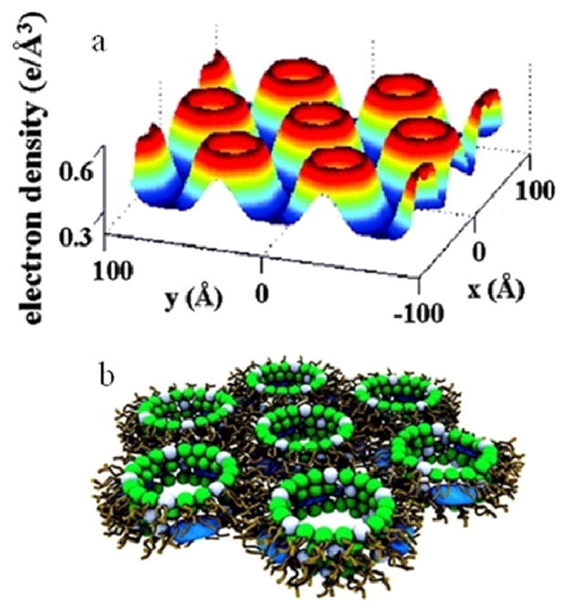
Detailed proposed model for AMO in lipid membrane analogous to schematic model (iv) in Figure 6. (A) Electron density profile (x, y) of the 2D unit cell for complexes formed by an AMO in a DOPG:DOPE = 20:80 lipid membrane showing an inverted hexagonal structure. The regions of lowest electron density correspond to lipid chains. Circular rims of high electron density surrounding holes of intermediate density correspond to lipid head groups surrounding water channels which have a diameter of 3.4 nm. (B) A proposed model of the unit cell. The white and green spheres represent head groups of zero intrinsic curvature (ex. DOPG, DOPC) and negative intrinsic curvature lipids (ex. DOPE), respectively. AMO molecules are represented by blue spherocylinders embedded in the membrane Reprinted with permission from reference 13.
Figure 9.
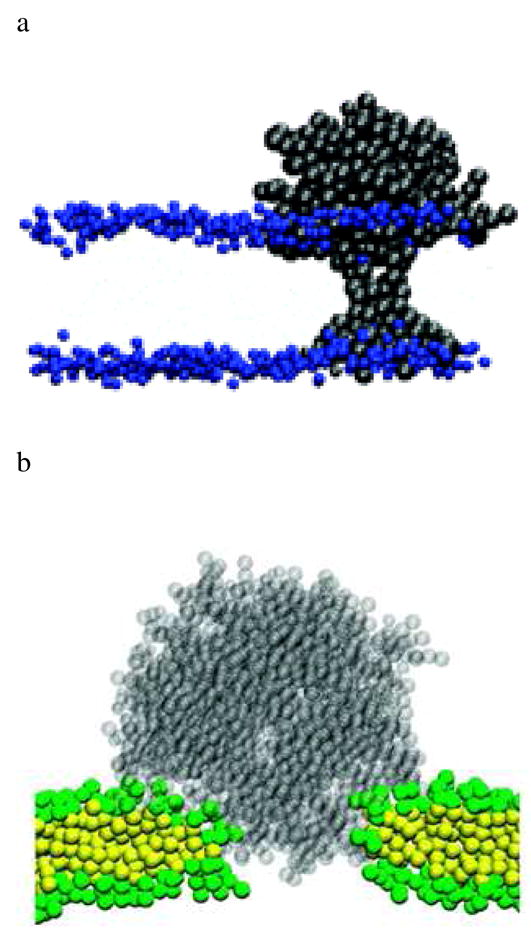
a) Detailed proposed model for G5 PAMAM dendrimer in lipid membrane analogous to schematic model (vi) in Figure 6. Snapshot after 0.5 μs of simulation. Black dots represent dendrimers, and blue dots represent headgroups of the DPPC bilayer. Reprinted with permission from reference 17. b) Detailed proposed model for G7 PAMAM dendrimer in lipid membrane analogous to schematic model (iv) in Figure 6. A snapshot of the dendrimer-induced pore in a DMPC bilayer at the end (160 ns) of the simulation G7 PAMAM. Transparent gray dots represent a G7 dendrimer. Green and yellow dots represent head and tail groups of DMPC, respectively. Water molecules and ions are omitted for clarity. Reprinted with permission from reference 16.
Significance
One of the hallmarks of the cell membrane is its ability to selectively control traffic into and out of the cell and maintain a separation between the cytosol and extracellular environment. In this report we have shown that at non-cytotoxic concentrations, G7-NH2 and G5-NH2 dendrimer, PEI, PLL, and AMO-3 cause a physical breach in the cell membrane by creating nanoscale defects. Defect formation times were measured to range from 1 – 100 ms. The defect size, as estimated by conductance change, is comparable to the holes measured via AFM (for the polymers) in supported lipid bilayers or SAXS (AMO-3) in a solution of lipid vesicles.4,8 The data reveal that tests focusing solely on gross toxicity are not sufficient to measure or understand nanoparticle- or AMO-induced membrane disruption, and in particular will not give a good understanding of the chronic effects of these materials on cells or tissue.
Recent reports indicate that many classes of nanoparticles, including those discussed in this report, are very facile at transporting material through tissue.22–26 The efficient induction of nanoscale holes in membranes provides a mechanism for at least some classes of nanoparticles. As these materials continue to be developed for use in biomedical, industrial, and consumer products, the implications of inducing porosity in tissue that comes in contact with nanoparticles will need to be investigated.
Experimental Procedures
Materials and Solutions
Poly(ethyleneimine) (PEI), poly-l-lysine (PLL), and polyethylene glycol (PEG) were purchased from Sigma-Aldrich. Generation 7 PAMAM dendrimers (G7-NH2) were synthesized at the Michigan Nanotechnology Institute for Medicine and Biological Sciences, University of Michigan. The synthesis of AMO-3 was previously reported.11–13 Pipette solution for whole-cell recordings (KINT) consisted of 140 mM KCl, 1 mM K*EGTA, 10 mM K*HEPES and was adjusted to pH 7.35 with KOH. The extracellular bath solution was a modified Tyrode solution consisting of 137 mM NaCl, 5.4 mM KCl, 0.5 mM MgCl2, 0.16 mM NaH2PO4, 3 mM NaHCO3, 5 mM HEPES, 5 mM glucose, adjusted to pH 7.35 with HCl and supplemented with 500 μM Ca2+.
Whole-cell patch-clamp
The 293A and KB cell lines were purchased from Invitrogen (Carlsbad, CA) and the American Type Tissue Collection (ATCC; Manassas, VA), respectively, and grown continuously as a monolayer at 37 °C and 5% CO2 in Dulbecco’s modified Eagle’s medium (DMEM, Gibco, Eggenstein, Germany) supplemented with 10% fetal bovine serum (FBS), 0.1 mM MEM Non-Essential Amino Acids (NEAA), and 1% Penicillin-Streptomycin. Ionic currents from single 293A cells were recorded using the whole-cell configuration of the patch-clamp technique. Recordings were carried out using an Axopatch 200B amplifier, Digidata1322A and pCLAMP 8.2 software (Molecular Devices, USA). Micropipettes were pulled from KIMBLE glass (#73813) on a horizontal puller (Sutter Instrument, USA). Pipette resistance ranged from 1 to 2.5 MΩwhen filled with KINT solution. Nanoparticle solutions were prepared by dissolving the desired amount of solid in the modified Tyrode solution. During experiments, free modified Tyrode solution or modified Tyrode solution containing nanoparticles was superfused into the chamber holding the cells via a peristaltic or syringe pump (at flow rate of 2.2 μL/s), respectively. A small well at the opposite end of the chamber was used to remove fluid at an equal rate via vacuum suction. The total volume of chamber was approximately 200 μL. In some experiments, the holding potential was ramped from −80 mV to 20 mV for 1 sec. In other experiments, the pipette potential was held at −70 mV and the current was low-pass filtered at 1 kHz and recorded as a function of time at 5 kHz sampling rate.
During voltage ramp experiments, stable records were obtained for at least 5 min before applying solution containing nanoparticles. For experiments where the membrane potential was held constant, stable I-V traces were obtained for at least 2 min and then a stable current as a function of time trace was obtained for another 1.5–2 min before application of nanoparticle solution. In all experiments, the access resistance (Ra) was checked periodically during recording. Cells with a Ra > 5 MΩ were excluded from analysis.
Supplementary Material
Acknowledgments
This research was supported by a grant from the National Institutes of Health, National Institute of Biomedical Imaging and BioEngineering (R01-EB005028).
Footnotes
Supporting Information Available. I-V curves for KB cells and PEI as a function of time are provided as Figure S1. I-V curves for 293A cells and AMO-3 as a function of time are provided as Figure S2. Table S1 contains a summary of the molecular weight and polydispersity of the G5-NH2, G7-NH2, PEI, and PLL used for this study.
References
- 1.Hong S, Bielinska AU, Mecke A, Keszler B, Beals JL, Shi X, Balogh L, Orr BG, Baker JR, Banaszak Holl MM. Bioconjugate Chem. 2004;15:774. doi: 10.1021/bc049962b. [DOI] [PubMed] [Google Scholar]
- 2.Hong SP, Leroueil PR, Janus EK, Peters JL, Kober MM, Islam MT, Orr BG, Baker JR, Holl MMB. Bioconjugate Chem. 2006;17:728. doi: 10.1021/bc060077y. [DOI] [PubMed] [Google Scholar]
- 3.Leroueil PR, Berry SA, Duthie K, Han G, Rotello VM, McNerny DQ, Baker JR, Orr BG, Holl MMB. Nano Lett. 2008;8:420. doi: 10.1021/nl0722929. [DOI] [PubMed] [Google Scholar]
- 4.Leroueil PR, Hong SY, Mecke A, Baker JR, Orr BG, Holl MMB. Acc Chem Res. 2007;40:335. doi: 10.1021/ar600012y. [DOI] [PMC free article] [PubMed] [Google Scholar]
- 5.Fischer D, Li YX, Ahlemeyer B, Krieglstein J, Kissel T. Biomaterials. 2003;24:1121. doi: 10.1016/s0142-9612(02)00445-3. [DOI] [PubMed] [Google Scholar]
- 6.Verma A, Uzun O, Hu YH, Hu Y, Han HS, Watson N, Chen SL, Irvine DJ, Stellacci F. Nature Materials. 2008;7:588. doi: 10.1038/nmat2202. [DOI] [PMC free article] [PubMed] [Google Scholar]
- 7.Zhang ZY, Smith BD. Bioconjugate Chem. 2000;11:805. doi: 10.1021/bc000018z. [DOI] [PubMed] [Google Scholar]
- 8.Mecke A, Majoros I, Patri AK, Baker JR, Banaszak Holl MM, Orr BG. Langmuir. 2005;21:10348. doi: 10.1021/la050629l. [DOI] [PubMed] [Google Scholar]
- 9.Mecke A, Uppuluri S, Sassanella TJ, Lee DK, Ramamoorthy A, Baker JR, Orr BG, Banaszak Holl MM. Chem Phys Lipids. 2004;132:3. doi: 10.1016/j.chemphyslip.2004.09.001. [DOI] [PubMed] [Google Scholar]
- 10.Ginzburg VV, Balijepailli S. Nano Lett. 2007;7:3716. doi: 10.1021/nl072053l. [DOI] [PubMed] [Google Scholar]
- 11.Arnt L, Rennie JR, Linser S, Willumeit R, Tew GN. J Phys Chem B. 2006;110:3527. doi: 10.1021/jp054339p. [DOI] [PubMed] [Google Scholar]
- 12.Yang LH, Gordon VD, Trinkle DR, Schmidt NW, Davis MA, DeVries C, Som A, Cronan JE, Tew GN, Wong GCL. Proc Natl Acad Sci U S A. 2008;105:20595. doi: 10.1073/pnas.0806456105. [DOI] [PMC free article] [PubMed] [Google Scholar]
- 13.Yang LH, Gordon VD, Mishra A, Sorn A, Purdy KR, Davis MA, Tew GN, Wong GCL. J Am Chem Soc. 2007;129:12141. doi: 10.1021/ja072310o. [DOI] [PubMed] [Google Scholar]
- 14.Noronha FSM, Cruz JS, Beirao PSL, Fatima Horta M. Infection and Immunity. 2000;68:4578. doi: 10.1128/iai.68.8.4578-4584.2000. [DOI] [PMC free article] [PubMed] [Google Scholar]
- 15.Hille R. Ionic channels of excitable membranes. Sinauer Associates; Sunderland, England: 1992. [Google Scholar]
- 16.Lee H, Larson RG. J Phys Chem B. 2008;112:7778. doi: 10.1021/jp802606y. [DOI] [PMC free article] [PubMed] [Google Scholar]
- 17.Lee H, Larson RG. J Phys Chem B. 2006;110:18204. doi: 10.1021/jp0630830. [DOI] [PubMed] [Google Scholar]
- 18.Lee H, Larson RG. Molecules. 2009;14:423. doi: 10.3390/molecules14010423. [DOI] [PMC free article] [PubMed] [Google Scholar]
- 19.Lee H, Larson RG. J Phys Chem B. 2008;112:12279. doi: 10.1021/jp805026m. [DOI] [PMC free article] [PubMed] [Google Scholar]
- 20.Kelly CV, Leroueil PR, Nett EK, Wereszczynski JM, Baker JR, Orr BG, Holl MMB, Andricioaei I. J Phys Chem B. 2008;112:9337. doi: 10.1021/jp801377a. [DOI] [PMC free article] [PubMed] [Google Scholar]
- 21.Kelly CV, Leroueil PR, Orr BG, Holl MMB, Andricioaei I. J Phys Chem B. 2008;112:9346. doi: 10.1021/jp8013783. [DOI] [PMC free article] [PubMed] [Google Scholar]
- 22.Oberdorster G, Oberdorster E, Oberdorster J. Environ Health Perspect. 2005;113:823. doi: 10.1289/ehp.7339. [DOI] [PMC free article] [PubMed] [Google Scholar]
- 23.Nigavekar SS, Sung LY, Llanes M, El-Jawahri A, Lawrence TS, Becker CW, Balogh L, Khan MK. Pharm Res. 2004;21:476. doi: 10.1023/B:PHAM.0000019302.26097.cc. [DOI] [PubMed] [Google Scholar]
- 24.Kim JS, Yoon TJ, Kim BG, Park SJ, Kim HW, Lee KH, Park SB, Lee JK, Cho MH. Toxicol Sci. 2006;89:338. doi: 10.1093/toxsci/kfj027. [DOI] [PubMed] [Google Scholar]
- 25.Geiser M, Rothen-Rutishauser B, Kapp N, Schurch S, Kreyling W, Schulz H, Semmler M, Hof VI, Heyder J, Gehr P. Environ Health Perspect. 2005;113:1555. doi: 10.1289/ehp.8006. [DOI] [PMC free article] [PubMed] [Google Scholar]
- 26.Duncan R, Izzo L. Adv Drug Delivery Rev. 2005;57:2215. doi: 10.1016/j.addr.2005.09.019. [DOI] [PubMed] [Google Scholar]
Associated Data
This section collects any data citations, data availability statements, or supplementary materials included in this article.


