Abstract
A multifunctional 9F intracardiac imaging and electrophysiology mapping catheter was developed and tested to help guide diagnostic and therapeutic intracardiac electrophysiology (EP) procedures. The catheter tip includes a 7.25-MHz, 64-element, side-looking phased array for high resolution sector scanning. Multiple electrophysiology mapping sensors were mounted as ring electrodes near the array for electrocardiographic synchronization of ultrasound images. The catheter array elevation beam performance in particular was investigated. An acoustic lens for the distal tip array designed with a round cross section can produce an acceptable elevation beam shape; however, the velocity of sound in the lens material should be approximately 155 m/s slower than in tissue for the best beam shape and wide bandwidth performance. To help establish the catheter’s unique ability for integration with electrophysiology interventional procedures, it was used in vivo in a porcine animal model, and demonstrated both useful intracardiac echocardiographic visualization and simultaneous 3-D positional information using integrated electroanatomical mapping techniques. The catheter also performed well in high frame rate imaging, color flow imaging, and strain rate imaging of atrial and ventricular structures.
I. INTRODUCTION
As intracardiac echocardiography (ICE) imaging catheters become more commonly used to guide interventional electrophysiology (EP) therapeutic procedures, their expanded capability in imaging and procedural guidance is in constant development. Recent reports have shown improvements in atrial fibrillation interventional procedures using ICE integrated with other available imaging modalities [1], [2]. We have taken this integration approach by building and testing a multifunctional catheter capable of both EP sensing and ICE imaging functions. The principal goal of our multifunctional catheter design is to improve the guidance of therapeutic interventional procedures to correct arrhythmias. These procedures are currently performed with high patient exposures to the ionizing radiation of fluoroscopy and require hours of time to confirm intracardiac catheter positions and procedural success. We believe that the integration of three-dimensional (3-D) anatomical mapping with ICE imaging will lead to powerful new methodologies in the interventional treatment of arrhythmias, and as well other intracardiac interventions.
Although ICE catheters have been in use now in various forms for some time, only limited descriptions of the important technical details of a side-looking phased-array ICE catheter design have been available. Our approach here is to generally describe the catheter, to focus in particular on critical aspects of the design such as the array elevation lens, and to describe our in vivo experience with our multifunctional catheter in a novel ICE integration with 3-D anatomical mapping.
A. Conventional Interventional EP Guidance and Early ICE Development
The gold standard image guidance tool in intracardiac EP is fluoroscopy, used to confirm catheter position and provide a general anatomical reference for the interventionalist. Fluoroscopic imaging, however, cannot provide sufficiently detailed anatomical information about cardiac anatomy and can misrepresent catheter position [3]. One study reported significant errors in atrial catheter perceived location based on fluoroscopy compared to ICE positional confirmation [4]. Procedural errors in lesion placement are not only inefficient, but can be harmful if critical structures such as sinus nodal tissue are inadvertently ablated. Using continuous ICE anatomical information, the positional accuracy of ablation catheter placement can be improved and fluoroscopy time reduced [5].
Intracardiac echocardiography catheter designs have existed for some time [6], [7], although multi-site use was not seen until the late 1980s and early 1990s when catheters with wire-driven rotating piezoelectric transducers were used clinically to investigate ultrasonic guidance of various intracardiac procedures [8]–[11]. These early mechanical ICE catheters [12] had some shortcomings as they were typically large (e.g., 10F, or approximately 3.3 mm in diameter), were not directly steerable (needed a steerable sheath), had limited tissue penetration due to a small circular aperture affecting transmitted power and depth of focus, had a slow frame rate (limited to 30 Hz), and were incapable of high quality Doppler or tissue velocity imaging (TVI).
The mechanical rotating 12.5-MHz intracardiac catheters from the mid-1990s were somewhat limited [13] in their usefulness due to echo attenuation, but other investigators [14] found that a 10F 10-MHz mechanically rotating catheter helped in confirming good ablation electrode contact and shortening of procedure times in porcine models. Foster and Picard [15] found that mechanical rotation catheters can produce accurate measurements of heart valves, but also saw that nonuniform rotational distortion in mechanical catheters and ring-down artifacts from phased-array catheters limit optimal performance. Epstein et al. [4] showed that mechanical rotational ICE could play a role in more accurately targeting ablation sites compared with fluoroscopy alone in the canine model.
The Mayo Clinic [16] demonstrated early success using a 8F rigid catheter with a high performance 7-MHz, 128-element, side-looking phased array in studies done with a canine heart model. Bruce et al. [17] were among the first to compare the 9F 9 MHz mechanical catheter and the newly FDA-approved 10F wideband (5.5–10 MHz) phased-array transducer with capabilities including pulsed wave, color, and tissue Doppler. The 10F phased-array device has been used in key studies since 2000 [18]–[20], and in 2005 an 8F version of the device was approved for human use.
From 2000 on, there have been several very innovative designs targeting advanced imaging arrays for EP procedures. Initially these were large prototype devices at 12F operating at 5 MHz [21], [22], but more recently they have improved in size to a 7F catheter equipped with a 5-MHz, 112-element, side-looking array for 3-D intracardiac imaging [23]. In 2004, the use of a highly integrated multifunctional catheter was described [24] as a 14F device with a 2-D matrix array of 112 elements for 5-MHz imaging surrounded by an ablation annulus operating at 10 MHz, and EP sensors near the catheter tip. Recently, a new 7F catheter integration effort was reported to guide EP interventions with a dual-purpose side-looking 128-element imaging and therapy array operating at 10 MHz [25], which is designed to image as well as ablate tissue around the ostia of left atrium (LA) pulmonary veins.
B. Multifunctional Guidance of EP Therapies
To treat atrial fibrillation, ICE can provide important guidance not only in identifying key anatomic structures, but also in direct ablation guidance and in avoiding and detecting therapeutic procedure complications such as micro emboli production during ablation and thrombus formation on sheaths and catheters [1], [26].
Guiding interventional EP therapies is clearly challenging. To add another dimension of positional information, we have integrated EP sensor electrodes near the distal tip array to utilize the electroanatomical mapping capability of the Ensite NavX (Endocardial Solutions, Inc. (St. Jude Medical), Minneapolis, MN) guidance system. The electroanatomical mapping technique uses concepts from impedance tomography and 3-D display technologies to allow the visualization of heart chambers “mapped” by the electroanatomical mapping catheter. Once a volume is mapped and displayed, the EP sensor-equipped ICE catheter as well as the mapping catheter can be continually sensed in 3-D position and displayed in real time. By integrating ultrasound imaging with spatial 3-D mapping, the multifunctional ICE catheter has the potential to achieve a new level of procedural guidance.
II. METHODS
A. Catheter Design
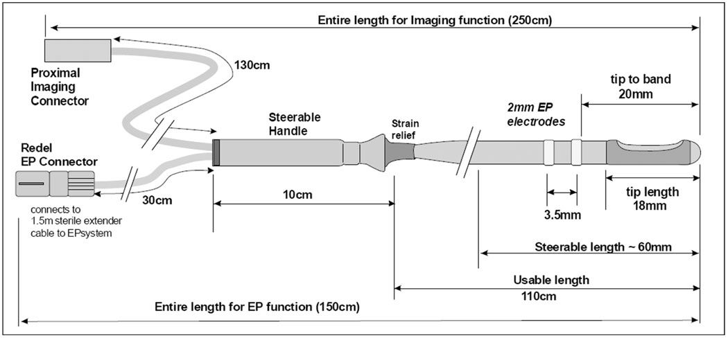
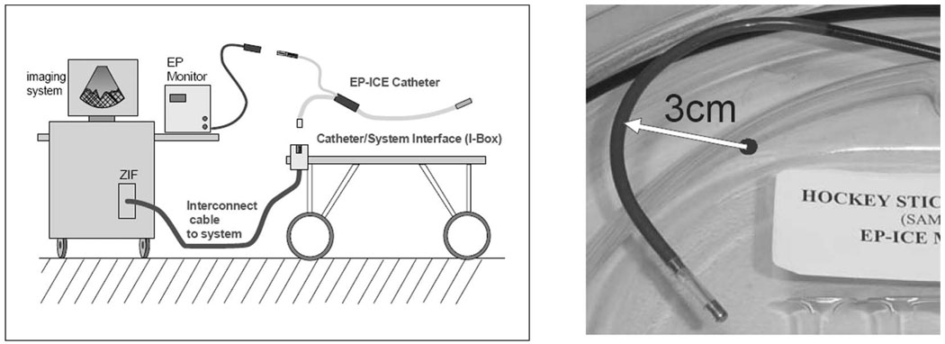
The 9F (3-mm diameter) shaft of the multifunctional ICE catheter is made of a biocompatible polymer with a reinforced proximal section for “push-ability” and good handling. The device is designed for single use in the EP laboratory under sterile conditions. The tip is rounded for safety, and may include a metal tip electrode or finished polymer tip, depending on the design style. The only exposed metal features are the standard metal EP electrodes which are mounted, depending on the design style, on the catheter shaft at the proximal side of the array or as an electrode pair on either side of the array. An interconnect termination box has been designed to offer a high utility, low cost catheter connection scheme for enabling easy and safe connection capability within the sterile field at the patient table. The catheter, named the HockeyStick, has dimensions as shown in Fig. 1, with interconnect diagram and an image of the “hockeystick” bend in Fig. 2.
Fig. 1.
The functional dimensions of the 9F HockeyStick catheter.
Fig. 2.
The general cable connection scheme for the combination catheter. The left panel shows the nondisposable trunk cable between the imaging system and the patient table, and the two separate connection paths for EP mapping and for imaging. The right panel shows the distal end of an early mechanical prototype steered in its minimum bend radius position.
B. Integration of EP Mapping Sensors
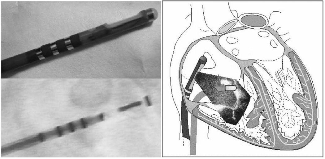
Several EP mapping sensor arrangements were implemented during catheter development. One design with which we have the most experience utilizes two sensor bands just proximal to the imaging array at the tip of the catheter. The sensor bands as EP mapping electrodes are able to sense local intracardiac potentials, providing valuable electrocardiographic data. The electrodes also serve another valuable function. When used with electroanatomical mapping apparatus and an applied electrical field gradient, they can track the 3-D position of the catheter. The internal catheter wires for each of these bands are routed, with good quality electrical isolation, to the EP connector which is connected to the EP monitor.
C. Steering
To enable bidirectional steering, two steering wires were needed in the catheter design. Each steering wire is housed in its own small lumen within the catheter shaft on opposite sides of the shaft. The steering handle, together with a longitudinally firm catheter shaft, form the remainder of the mechanical steering system that allows the sector image to be oriented on either the outside or the inside radius of the catheter steering bend. The image plane is essentially in the same plane as the steering bend. The torque ability of the catheter shaft enables fine adjustment of image plane positioning.
D. Interconnect and Imaging Array Cable
The catheter was designed to use an imaging system connector with the necessary attributes of a small, sterilizable, and disposable connector. This critical link to the imaging system needs to be small, low cost, and reliable, and needs to possess a good retention force, while also protecting user safety with recessed system-end live electrode contacts. A simple but very useful system interface called the Interface Box (I-Box) was designed to allow a 2.5-meter trunk cable connection to be made to the imaging system zero insertion force (ZIF) connector. The I-Box was designed with a 100-pin SAMTEC BSH series connector mounted directly to a well-shielded interconnect printed circuit board. A trunk cable is assembled with a shielded bundle of 40 AWG coaxial cables to link the I-Box with the system ZIF connector.
The imaging array cable within the catheter is a shielded bundle of 64 individual microcoaxes (Tyco Electronics/Precision Interconnect, Wilsonville, OR) that is nominally 1.96 mm in diameter and occupies a large portion of the catheter shaft lumen. The individual coax members are made with a 48 AWG center conductor, a 0.033 mm fluoropolymer insulation, and a 52 AWG served shield offering better than 95% coverage with a 0.015 mm polyester film covering that produces a total coax diameter of 0.165 mm. The 64 coaxes are assembled together with a 0.05 mm binder tape, 46 AWG shield braiding, and an additional 0.05 mm wrap of fluoropolymer tape. The characteristic impedance is 50 ohms.
E. Imaging Array Piezoelectric Design
The 64-piezoelectric array elements are arranged within the tip enclosure at the distal end of the catheter to form a side-looking image plane with a centered sector image orthogonal to the catheter axis. The active imaging aperture is 2.6 mm in elevation and 6.4 mm in length with a 100-micron element pitch. At 7.25 MHz, the 2.6-mm elevation length provides a good passive focus for imaging in the 10-to 40-mm range, and phased-array focusing in the image plane is designed to produce an azimuthal resolution close to 0.5 mm.
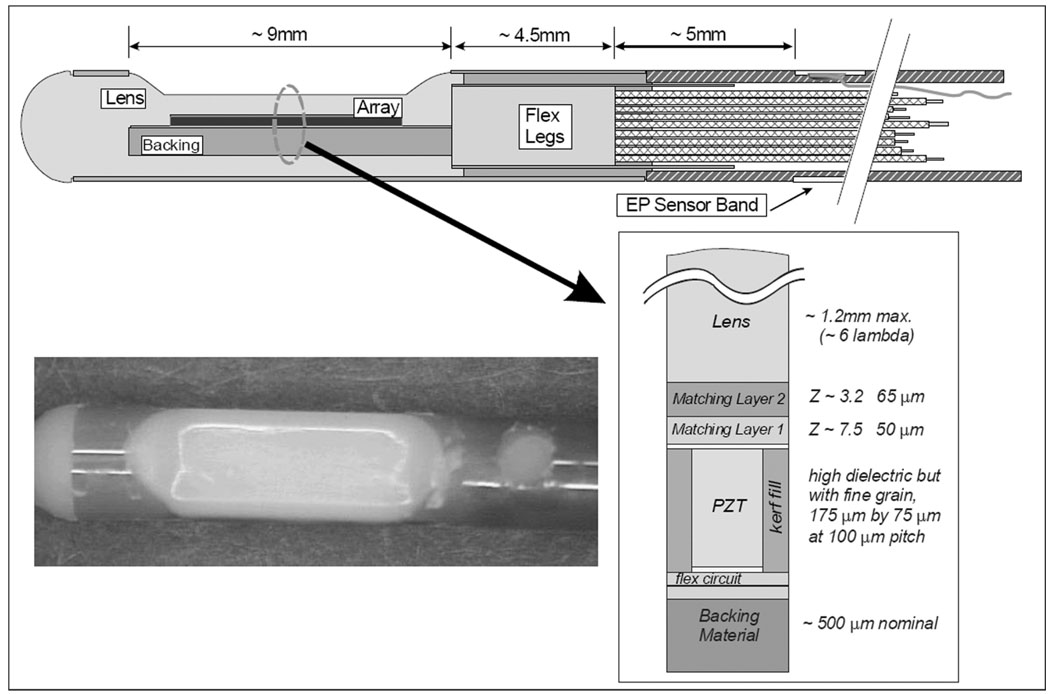
The array is made of a standard 2-2 composite with absorbing kerf fillers. To achieve a fractional bandwidth (FBW) greater than 50%, a double matching layer was employed with the first layer targeted to be 7.5 MRayls at 50 microns and the second layer 3.2 MRayls at 65 microns. The array assembly was bonded to a 25-micron polyimide flex circuit with a high absorption backing. The flex circuit is folded on itself at the tip of the array to allow adequate paths for the 64-element connections, so the flex is doubled layered under the PZT stack as shown in Fig. 3, creating a total double flex thickness of approximately 85 microns with the glue layer. Design parameters are given in Table I.
Fig. 3.
The tip region of the HockeyStick catheter. The flex folds back upon itself at the distal tip so that there are actually two flex layers under the array, with an adhesive layer between them. The photo shows a HockeyStick catheter tip region with a tapered lens design.
TABLE I.
HockeyStick Piezoceramic Array Design Parameters.
| Ceramic post material | Elevation width (mm) |
Element thick. (microns) |
Element width (microns) |
Array pitch (microns) |
||
|---|---|---|---|---|---|---|
| TRS-600FGDH or TRS-HK1-HD | 2.6 | 175 | 75 | 100 | ||
| Material | Thickness (microns) |
Long. atten. (dB/mm) |
Density (kg/m3) |
Vlong. (m/s) |
Z (kg/m2 sec) |
Vshear (m/s) |
| Outer matching layer | 65 | 13 @ 30 MHz | 1150 | 2650 | 3.05E+06 | 1270 |
| Inner matching layer | 50 | 13.8 @ 30 MHz | 3870 | 1900 | 7.35E+06 | ~900 |
| Kerf/backing material | ~1000 | 12.9 @ 10 MHz | 1408 | 2360 | 3.32E+06 | ~1131 |
| Kapton flex circuit (2-layer thickness) | ~85 | 3.29 @ 20 MHz | 1420 | 2227 | 3.16E+06 | ~1000 |
The array lens material was selected to be a castable biocompatible polyurethane (RP 6400; Freeman Mfg. & Supply Co., Avon, OH) with an acoustic velocity as close to that of water as reasonably possible, since the preferred round lens cross section would represent as much as a 6-lambda thickness at the thickest point in the lens. The acoustic attenuation of this lens material is significant at 10 dB/cm/MHz for one-way transmission.
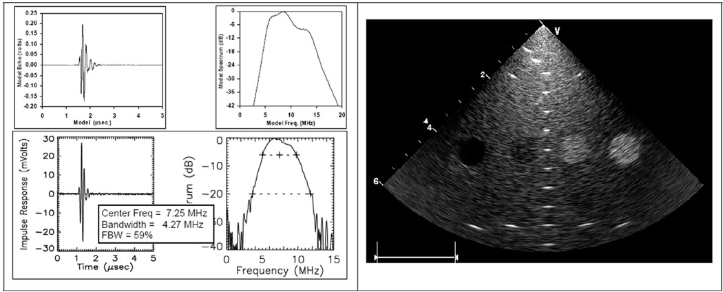
Laboratory testing of early array prototypes showed an average element center frequency of 7.25 MHz and a band-width of 4.27 MHz. There is a small but noticeable downward shift in center frequency from the design, resulting from lens attenuation. A discussion on the lens design and material comparisons is continued in the sections below.
F. Imaging Array Acoustic Beam Simulation and Optimization
The acoustic lens of the multifunctional catheter is a critical element in the design of the device. The acoustic lens profile ideally would be of a round shape which would be optimal for use in the body’s tortuous vasculature and would make manufacturing assembly easier as well. A round lens, though, would require the lens material to satisfy multiple essential design requirements that include 1) material biocompatibility, 2) low acoustic loss in two-way transmission through the lens, 3) nearly tissue-matched acoustic velocity, and 4) good mold performance and adhesion characteristics in assembly. As an alternative, the lens can be tapered in thickness, which can help reduce potentially undesirable elevation beam performance if the lens material velocity is not matched to tissue velocity, but does not provide the very best physically smooth outer profile. A controlled, multivariate test of reasonable candidate materials that are close to our desired characteristics might identify a better material, but prototype testing for design parameter optimization would be expensive and time consuming. We elected to solve the issue with a good analytical investigation, confirmed with Schlieren imaging and hydrophone tests.
The assessment of acoustic lens performance can take several paths. The classical lens formula that is usually used to control first-order elevation beam performance does not help very much because it is applied typically with a very large lens radius for subtle phase adjustments to the native beam. The standard lens formula [27],
| (1) |
where daf is the depth-at-focus, roc is the radius of lens curvature, and Vlens and Vmed are the acoustic velocities of the lens and medium, respectively, can be useful for finding the radius of curvature needed with a large radius and slow lens material. The relation is derived by assuming that the geometric angles are small, i.e., that sin(θ) ~ θ, where θ is the angle, with apex at the center of lens curvature, between the beam centerline and a point on the surface of the lens. Although this expression provides some insight, it does not provide adequate details about the actual beam character with changes in frequency, material attenuation, or a partially flattened (“tapered”) lens shape.
The beam-forming simulation we use calculates the elevation beam profile in two distinct steps. The first step uses the transducer aperture and lens properties to calculate an intermediate aperture on the surface of the lens itself, made up of well spatially sampled complex pressure points; the second step uses Huygen’s principle to calculate the beam field points from the intermediate lens surface aperture. The elevation beam model used in our study here does not address acoustical coupling issues with the transducer stack; however, all of the lens materials considered in our study have an acoustic impedance reasonably close to that of water, so first-order coupling effects are minimal. Lens speed, shape, and attenuation are certainly important to us and are carefully considered.
1. Elevation Beam Modeling Foundation
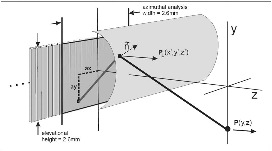
The catheter array elevation beam modeling geometry is shown in Fig. 4 and Fig 5. The scalar diffraction expression we use contains a Green’s function that includes bandwidth and an implicit inclination factor to obtain the desired pressure vector in the z direction. This particular version of the well-known expression, in Cartesian coordinates, is
| (2) |
where Pa is the complex pressure at the aperture, R is the beam ray distance from an aperture plane coordinate to a particular field coordinate, and dA is the incremental summation area on the aperture. A complex wave number k = (ω/cm + jα) is used here, where cm is the speed of sound in the medium, ω is the radian center frequency for the transmission signal used, and α is the medium’s attenuation coefficient in Nepers/m. The bandwidth coefficient γ is defined as FBW/0.4λ with units of m−1, where FBW is the fractional bandwidth of the acoustic transmission and λ is the wavelength in the medium at the center frequency.
Fig. 4.
The array, lens, and elevation field geometry. A single intra-lens acoustic path is shown that helps to produce a new Huygen’s point on the lens surface. This new calculated point describes a complex vector pressure normal to the lens surface. The Z-component of the complex pressure is then used to produce the pressure estimate in the Y-Z field.
Fig. 5.
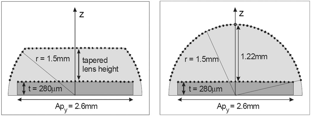
The elevation-depth plane at x = 0 showing the serial computation apertures with transducer array and lens surface sample points. The plot in the left panel shows the sampling used for the points with a tapered lens surface, and the right panel shows the sample points in the full round lens case.
2. Application of the Rayleigh-Sommerfeld Equation and Huygen’s Principle
The field pressure along the depth and elevation axes can be used as a descriptive indicator of beam performance. In essence, we wish to investigate the dependence of axial beam energy with variations in lens material and shape, and further to determine how these variables affect the beam with changes in frequency as well. Because we are primarily interested in elevation effects due to the lens, we assume the transducer and excitation are uniform in azimuth and treat azimuthal beam-forming as an independent problem.
We can make use of the Rayleigh-Sommerfeld integral and adapt its use for the investigation through the incorporation of lens shape, material, and echo bandwidth. To consider the lens shape we will use Huygen’s principle and first calculate an array of new point sources on the surface of the lens prior to a final calculation of the field pressure. With regard to lens shape variants, we have assumed that the “thinner” lenses are simply truncated in a manner as shown in Fig. 5(a). More complex shapes with the flat sections tapered in long radii are possible to consider, but not considered practical for a catheter “cast in place” lens assembly method. To accommodate material characteristics, we will establish mid-band wave lengths for the lens and body tissue respectively and incorporate lens and tissue attenuation in the study.
A segment of the intracardiac imaging catheter 64-element array with lens is shown in Fig. 4, with an elevation aperture of 2.6 mm and a maximum azimuthal aperture of 6.4 mm. The aperture used in the beam simulations is a 2.6-mm-square aperture sampled at points “ax” and “ay” with a pitch of λ/2. The lens surface aperture is a 3-D situation with the x = 0 planar sampling point schemes shown in Fig. 5, where the transducer array backside flex circuit defines the center of radius for the lens, thus creating an array surface offset from the flex plane by the complete array thickness, or approximately 280 microns. Consequently, the full thickness lens for the 9F (3-mm) catheter diameter at the elevation origin, y = 0, is the catheter radius less the transducer thickness, or 1.22 mm. The lens samples are spaced evenly on the lens surface regardless of a round or tapered lens shape at a pitch of λ/2 to assure good spatial sampling uniformity. The field examined is referenced to the surface of the transducer array so that the water/tissue interface for a round lens is at z = 1.22 mm, and thus a convenient starting point of 1.5 mm was always used in the simulations performed, regardless of lens shape.
We would like to analyze with high accuracy the beam behavior in elevation and depth for the intracardiac catheter lens with various shapes and lens speeds. Geometric acoustics (as in ray optics) could be employed, but in addition to each individual ray refraction calculation, we would also need to attend to the resulting sample point density on the intermediate virtual aperture that would be subsequently used for acquiring the points in the beam field at all depths beyond this intermediate aperture. Since we want to look at the full-round lens with a radius of ~7.5λ as well as tapered lens structures, the application of Huygen’s principle to calculate an intermediate aperture on the surface of the lens itself has great appeal for accuracy and relative ease in a computer-aided simulation.
To acquire the effective pressure distribution on the lens surface for the determination of the elevation beam in the insonified medium, we first consider the uniform pressure Pa (ax, ay, 0) at the transducer-lens interface without concern for the efficiency of transducer lens coupling. We will consider this our “first” of two serial apertures which includes the square transducer face region of 2.6-mm elevation and also 2.6 mm in azimuth. By taking advantage of symmetry in the azimuthal plane, we can obtain the elevation beam points on the 3-D lens surface from just the positive x-axis points of the transducer array surface aperture, or the “first aperture.” The “second,” or intermediate, virtual aperture is found, then, as a set of 3-D complex and time-delayed lens surface points given by
| (3) |
where Pa(ax, ay, 0) is the complex pressure at the transducer face aperture, and R(ax, ay, 0, x′, y′, z′) is the beam ray distance from an aperture plane coordinate ax, ay, 0 to a particular x′, y′, z′ field coordinate on the lens surface. The bandwidth coefficient γL, based on the wavelength in the lens medium, is distinct from the coefficient γm used for the calculation in the tissue medium. The pressure vector on the lens surface is scaled by the unit area of the sampled transducer face aperture, which is given by ΔAxd, the area defined by the square of the λ/2 sampling dimension.
The second step in the calculation of the elevation beam in the tissue medium involves the use of the new lens surface aperture. The complex pressures at the uniformly distributed point sources on the surface of the lens are delayed, weighted, and summed to calculate the pressure at each field point:
| (4) |
The second step calculation is similar in form to the first, with symmetry in the x plane permitting half of the computations that would otherwise be needed in the elevation beam field. Using a z-axis sampling of 0.9λ̣ the elevation beam field calculation required 48 seconds using MathCad (Parametric Technology Corp., Needham, MA) and an ordinary laptop PC (DELL Inspiron-5100 with a 2.4-GHz Pentium4, and 512-MB memory). To establish a reference comparison between the well-known analytical circular aperture solution and the simulation method performed, the simulation z-axis elevation beam result for the two serial apertures of a circular array plane section coupled to a “full round elevation lens composed of water” (i.e., using a circular segment array plane and a curved lens surface as the two Huygen’s apertures) agreed very well in both near- and far-field regions with the well-known analytical solution for the z-axis response using a circular aperture [28].
3. Computations to Find the Key Design Constraints on Catheter Lens Construction
Elevation beam simulations were carried out to study the effects of various lens materials and lens shapes under typical in vivo conditions. Three lens materials were examined as suitable candidates. Their material characteristics are shown in Table II. These materials are RP 6400, Bacon430 (Bacon Industries, Inc., Watertown, MA), and Santoprene (Advanced Elastomer Systems, Akron, OH), all with known sound velocities at body temperature as well as room temperature acquired from our own laboratory measurements that compare favorably with other sources as well [29], [30]. Each material has both good and bad attributes. As stated earlier, the best candidate should not only provide good elevation beam-forming capability, but also allow for easy and reliable casting and possess good biocompatibility. The Bacon430 and the RP 6400 are both two-part polyurethanes that can cure at room temperature or in an oven for an accelerated cure. The Santoprene is a biocompatible, low attenuation thermoplastic elastomer that can be shaped by heating but would be challenging to use in a catheter unless it is preformed and glued into place.
TABLE II.
Material Characteristics for Elevation Beam Study.
| Material | Hardness, Shore A |
VI @ 25C (m/s) |
VI @ 37C (m/s) |
Density (g/cm3) |
ZI (MRayl) |
Loss (dB/cm/MHza) |
a |
|---|---|---|---|---|---|---|---|
| RP-6400 | 52 | 1540 | 1480 | 1.04 | 1.54 | 10 | 1 |
| Bacon 430 | 70 | 1870 | 1746 | 1.10 | 1.92 | 7.7 | 1 |
| Santoprene | 65 | 1535 | 1474 | 0.97 | 1.43 | 5 | 1 |
| water | — | 1494 | 1521 [28] | 1.00 | 1.52 | 0.0022 | 2 |
| blood | — | — | 1590 [31] | 1.06 [34] | 1.68 | 0.16 [34] | 1.21 |
| cardiac muscle | — | — | 1595 [32] | 1.06 [34] | 1.69 | 0.52 [33] | 1 |
Since the lens polymers under consideration possess acoustic impedances close to that of the medium, the transmission coefficient at the lens surface boundary is ignored, in addition to other transmission coupling factors such as the mass loading effects of the lens on the array elements.
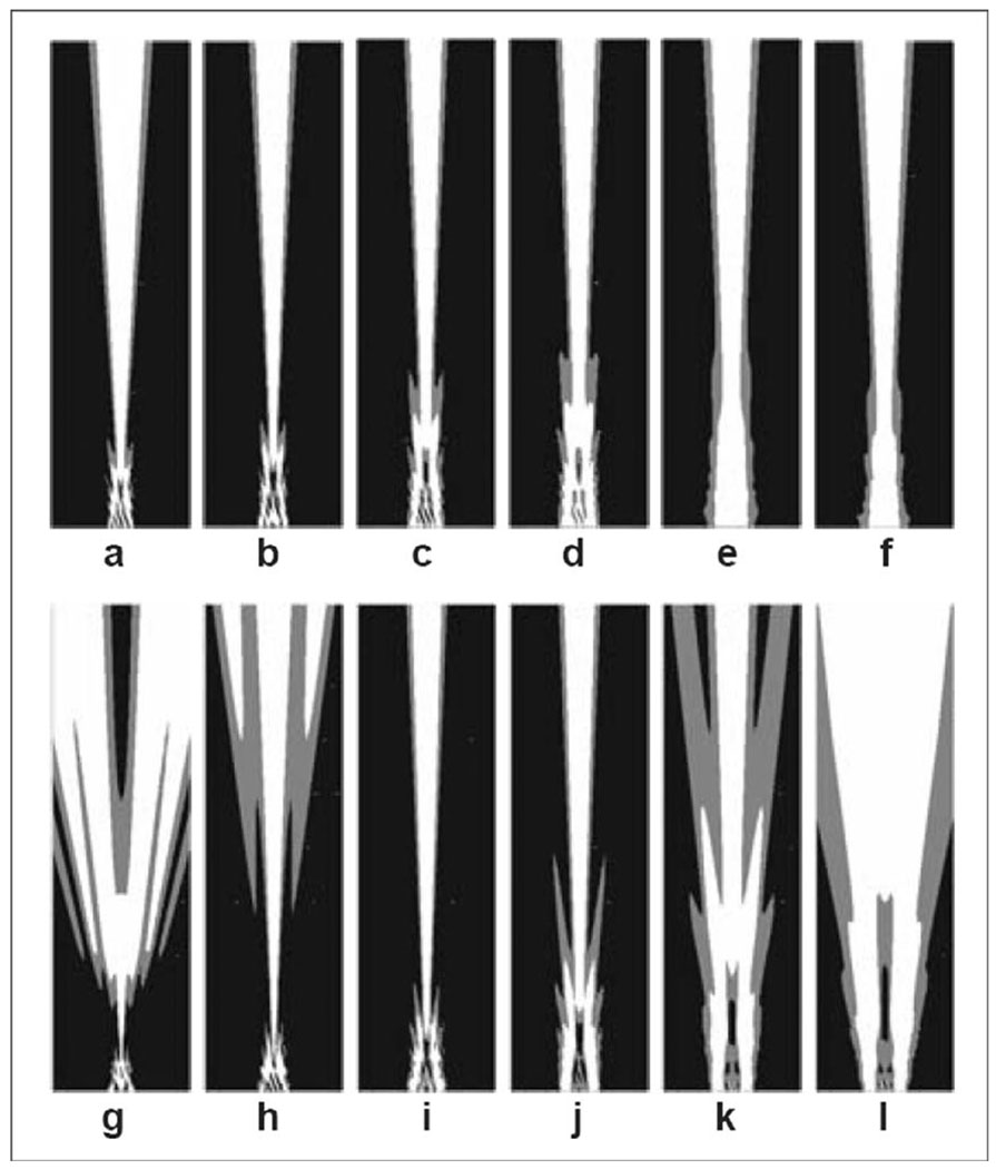
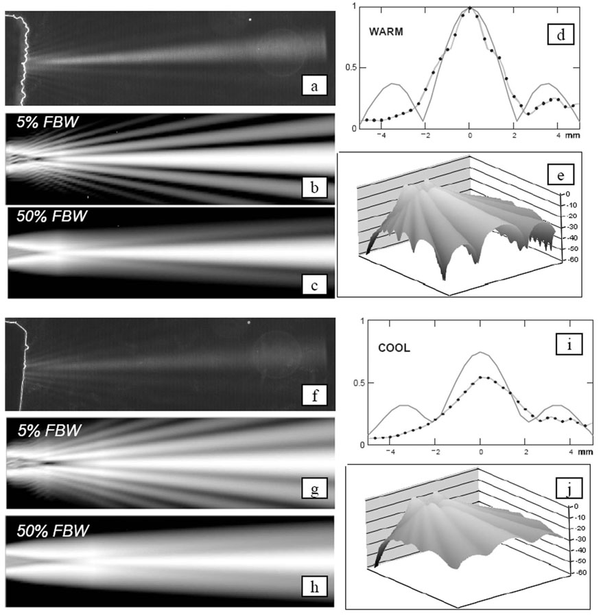
A simulation study was conducted to examine the effects on the elevation beam with lens speed and shape as the primary study variables, and with lens attenuation assumed to be 10 dB/cm/MHz, as in the case of a typical polyurethane lens material. Two sets of beam plots are shown in Fig. 6, where the tapered lens (top row) shows a relative insensitivity to lens speed, but the full round lens (bottom row) shows a considerable dependence.
Fig. 6.
The simulated two-way elevation beams of the tapered lens at 0.7-mm thickness (top row) and the full round lens at 1.22-mm thickness (bottom row) with lens materials of six different speeds (columns) at 7.25 MHz and 5% fractional bandwidth transmission signals. All beam plots are normalized at every depth, and plot dimensions are 10 mm in elevation, and 1.5 to 37.5 mm in depth (relative to the array top surface under the lens) with the white at −6 dB and gray at −12 dB beam contours. Both the tapered and the full round lens speeds are in meters per second and relative to a tissue medium speed. The relative speeds for tapered lens are: (a) −500, (b) −300, (c) −100, (d) 0, (e) +300, and (f) +500; and for the round lens: (g) −300, (h) −200, (i) −100, (j) 0, (k) +100, and (l) +200.
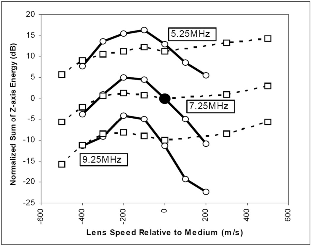
A single-point estimate may be used to describe elevation beam focusing quality for each of the 12 beams shown in Fig. 6; these estimates are plotted in Fig. 7 (see middle solid and dash set at 7.25 MHz). Fig. 7 has two families of curves, the solid group represents the full round lens case, and the dashed line group the tapered lens case. Each family is normalized to the respective case at 7.25 MHz with the lens speed matched to the medium (see large center point). In plotting single point estimates of elevation beam quality, we do not use “peak focus” pressure, due to the concern that a very slow speed lens, for example, will tend to focus in the near field but produce a poorly focused beam along the z-axis, e.g., the case in Fig. 6(g). The best elevation beam will maintain as much energy along the z-axis as possible. We define the metric for the normalized sum of z-axis energy (NSZE) to be
| (5) |
where the transmitted pressures along the z-axis are PM (0, z) and PW (0, z). The former is the calculated pressure in a tissue medium with a particular lens studied, and the latter is the calculated pressure in water without any lens. The medium acoustical impedance is assumed to be nominally equivalent in tissue and water so that both the impedance and temporal factors vanish. A strong, well-collimated beam will show a large value of NSZE. The simulation results indicate a frequency dependence effect on the acceptable range for the lens speed relative to the medium. It appears that a lens speed of −155 m/s relative to the medium is optimal for 7.25 MHz, and the two-way pulse echo half-power limits indicate an acceptable tolerance of ±125 m/s. The lower and upper band simulations shows lens speed center and tolerance of 155 ±145 m/s and 187 ±117 m/s, respectively.
Fig. 7.
The computational summary result of lens shape, speed, and operational frequency on elevation beam quality. A comparison is shown of normalized (based on the case at the central point) two-way elevation beam energy sums on the center (z) axis for center frequencies of 5.25, 7.25, and 9.25 MHz and 37°C tissue environment conditions with both a full round lens with radius 1.5 mm and center lens thickness of 1.22 mm (solid lines), and a tapered lens of thickness 0.7 mm (0.52 mm less thick than the round lens, dashed lines) with a variation in lens speed relative to the medium speed. The lens attenuation is fixed at 10 dB/cm/MHz and the medium attenuation is assumed to be 0.52 dB/cm/MHz. The simulations were done at 5% FBW and for depths from z = 1.5 to 37 mm.
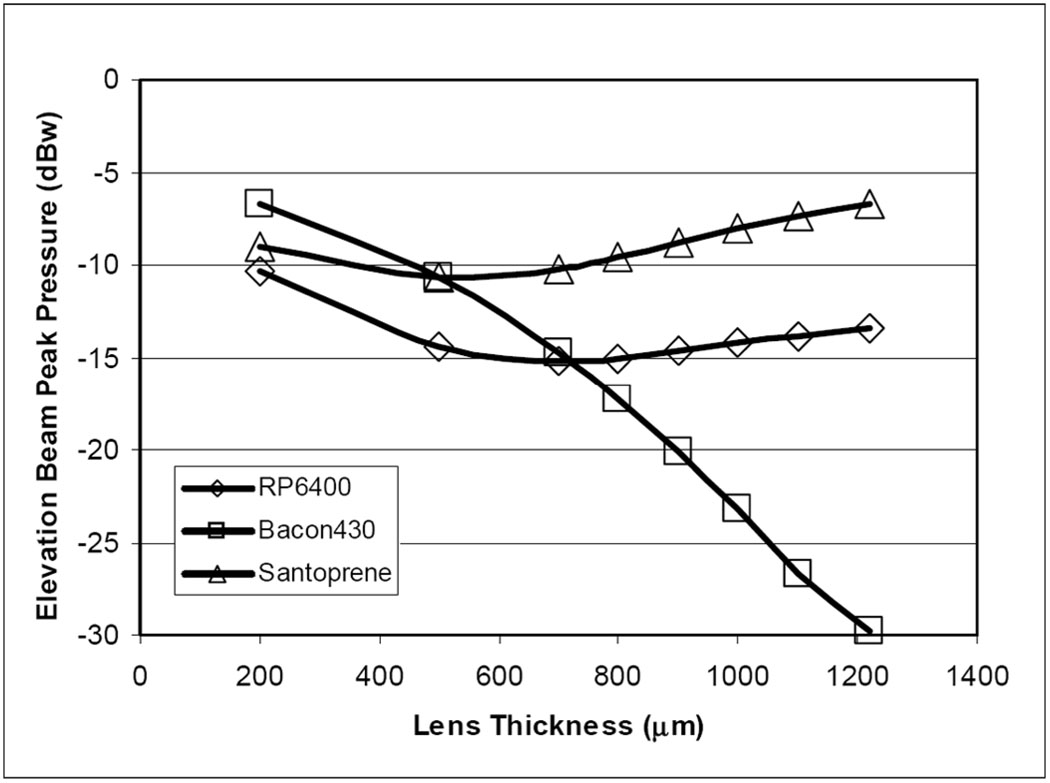
Additional elevation beam simulation analysis, using a conventional normalized pressure metric, predicts the peak pressures with a variation of lens thicknesses for the three lens material candidates. Fig. 8 shows the peak pressure response in decibels, normalized to the response with the lens replaced by water, of the three lens materials as lens thickness is varied from 0.20 mm microns to a full round thickness of 1.22 mm in each case. As the lens is thickened, the comparatively fast material (Bacon430) shows a monotonic drop in peak pressure with lens thickness, whereas the other two slower materials show a “recovery” in the elevation peak pressure due to a beneficial focusing effect.
Fig. 8.
The simulated response of the elevation beam relative pressure at the focal peak as a function of the lens thickness. Three lens material candidates were examined in lens thicknesses from 0.2 mm to a full round lens at 1.22 mm.
III. RESULTS
A. Transducer Array Characterization
The HockeyStick catheter arrays were built with both the TRS-600 and the TRS-HK1 piezoceramic materials (TRS Technologies, Inc., State College, PA) as the foundation of the 2-2 composite high efficiency design. The vast majority of our experience in this design is based on use of the TRS-HK1 material. The finished arrays were tested for pulse echo and impedance characterization. The single-element transducer tank circuit model components for this design appear to be 27 pF, 500 ohms, 19.5 µH, and 16 pF for C0, Rx, Lx, and Cx, respectively, where C0 is the bulk capacitance and the others are the series arm components that determine the resonant qualities of the transducer.
The series (fs) and parallel (fp) resonant frequencies, 8.6 MHz and 11.8 MHz, respectively, were obtained from the model to determine the thickness mode coupling coefficient kt for the composite array material [35], which appears to be approximately 0.72. The KLM model result shown in Fig. 9 predicts a center frequency of 7.67 MHz and an FBW of 68%; the laboratory data in Fig. 9 show the results of an early catheter built with corresponding values of 7.25 MHz and 59%, respectively.
Fig. 9.
The HockeyStick catheter array with an RP 6400 full round lens configuration. 1-D KLM model result is shown at upper left; pulse-echo test results from the second device built, HS-2, are shown at lower left. The right panel shows a standard target phantom result for phased-array imaging with an early prototype to a 60-mm depth.
B. Catheter Testing and Lens-Dependent Elevation Beam Forming
HockeyStick catheters with lenses both full round and tapered were built and characterized. The primary means of testing the devices while in process was electrical capacitance measurement of each of the 64 channels to determine open or shorted conduction pathway conditions. The individual elements exhibited measured capacitances typically in the 30- to 40-pF range (including the parasitic capacitance of the measurement technique) while the coax cable itself was approximately 260 pF. This capacitance ratio was sufficient to permit easy inferential assessments to steer any necessary rework.
Schlieren optical imaging (Onda Corp., Sunnyvale, CA) of the HockeyStick beams, both in azimuth and elevation, were performed to help in the understanding of the effects caused by the lens. The azimuthal Schlieren plots showed results in accordance with the expected focusing, and the phantom images were quite acceptable, as demonstrated in Fig. 9. The best azimuthal resolution expected, for a depth of 30 mm, for example, is close to the product of wavelength and f-number, with a full aperture active in receive producing the result of approximately 0.22 mm times 30/6.4, or about 1 mm. This is reasonably accurate for continuous wave (CW) and will be degraded somewhat at 59% FBW to become about 1.35 mm.
Schlieren elevation beam tests were performed with the full round lens catheters and the tapered lens devices in baths at room temperature (~21°C) and warm (~37°C) conditions. In all cases the lens material was RP 6400. Fig. 10 shows the Schlieren test bath results for the round lens/warm bath and round lens/cool bath conditions. The simulated (one-way transmission case) beams are also shown for each case. It should be noted that for the two temperatures, the simulation peaks have been determined to be −5.9 dBw and −9.5 dBw, respectively, all estimated with a normalization to the elevational peak simulation result of a no-lens/cool water bath case.
Fig. 10.
Simulation and laboratory comparisons of a full round lens beam performance at 37°C (a)–(e) and 21°C (f)–(j) water bath conditions. The Schlieren images (a) and (f) show elevation focusing with a narrow band signal at 7.25 MHz at warm and cool temperatures with image dimensions of 10-mm total elevation width and a depth of 37 mm. The simulation plot sets [(b), (c), (e), and (g), (h), (j)] show the expected one-way elevation beam results for the same plot dimensions as the Schlieren, but with the normalized-at-every-depth plot intensity ranges of 18 dB, 18 dB, and 60 dB, respectively. The elevation beam profiles (d) and (i) show a normalized comparison of predicted profiles (solid) and hydrophone data (points) collected at a depth of 20 mm with a narrow-band 4-MHz test signal. The calculated elevation peak pressures normalized to a no-lens condition in a cool bath are −5.9 dBw and −9.5 dBw for the warm and cool baths, respectively.
Hydrophone (HGL-0200; Onda Corp.) measurements of the HockeyStick catheter elevational beam performance were made, using a low, narrow band edge frequency of 4 MHz and a beam depth of 20 mm, at warm and cool water bath conditions.
C. Animal Studies
More than 10 Yorkshire pigs weighing in the range of 34 to 55 kg were studied to examine the capabilities of the multifunctional HockeyStick catheter in combination with standard EP mapping and ablation catheters within the right atrium. ICE imaging was performed using a commercial ultrasound imaging system (GE-Vingmed Vivid 7; GE Medical Systems, Milwaukee, WI) in standard imaging modes, including color and pulsed Doppler, tissue Doppler, tissue velocity (TVI), strain rate (SRI), and tissue synchronization (TSI) imaging. High display rates at 150 frames/s were commonly used.
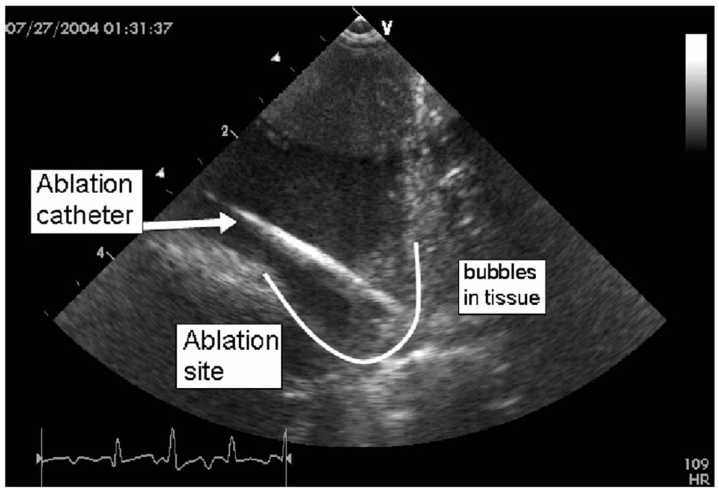
The pig studies yielded useful ultrasound imaging guidance indicators while simultaneous tissue ablation was performed (Fig. 12) using a separate ablation catheter with 50 Watts of RF power delivery capability. Tissue motion tracking of arrhythmias was interpreted using strain rate imaging data derived from tissue velocity imaging. Experimental designs were proposed to track multiple spatial velocity gradients at specific heart wall sites by displaying in real time their high fidelity tissue motion to aid in the assessment of sinus rhythm abnormalities.
Fig. 12.
A HockeyStick catheter image of the atrio-ventricular sulcus region in the right atrium of a pig during an active RF ablation procedure. The ablation catheter itself, the lesion site, and bubbles forming during prolonged ablation are clearly visible.
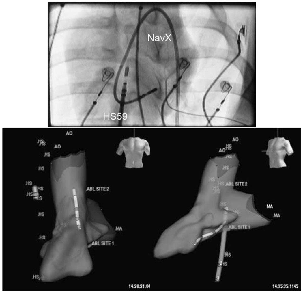
A NavX electroanatomical mapping system with multiple lead inputs and full 3-D software mapping tools was used to perform both intracardiac volume mapping and integration experiments with the HockeyStick catheter (Fig. 13). The EP sensor connector of the HockeyStick ICE catheter was connected directly to the NavX system, which allowed both the HockeyStick and the NavX catheter to be simultaneously visualized on the NavX system. Fig. 13 shows the HockeyStick on the right side of the heart in the right atrium (RA) while the NavX catheter is shown in the left ventricle (LV) after completing the 3-D mapping of that chamber.
Fig. 13.
The anterior view fluoroscopic image at the top shows the NavX mapping catheter looped on itself in the left ventricle (LV) of a pig, while the HockeyStick is shown in the RA. The two views at the bottom show the 3-D volume of a pig LV mapped by a NavX electroanatomical mapping catheter; the HockeyStick catheter (labeled “HS”) is in the RA while the slightly smaller NavX catheter is seen in the left ventricle. Both catheters were independently steered and could be tracked in a continuous 3-D mode very easily.
IV. DISCUSSION
A. HockeyStick Lens Elevation Beam Acoustic Performance
In addition to the fundamental performance of the array as an efficient acoustic energy transduction device, the optimal operation of the HockeyStick catheter lens itself is vital in high performance ICE imaging. Since it is quite expensive in time and materials to build large numbers of devices and conduct extensive tests, it seems to be a good approach to model the anticipated performance of potential designs. To be reasonably complete, a lens elevation beam-forming simulation was attempted to establish the parameter boundaries of ICE catheter lens design to include at least 1) material speed, 2) lens shape, and 3) frequency range.
To better understand the lens, we made continued use of opto-acoustic Schlieren beam- and hydrophone-based measurements to aid, in particular, the characterization of the round lens beams in both cool and warm bath conditions. The Schlieren image and hydrophone test results were obtained for only a limited number of the actual beam configurations. However, based on quantitative tests and our general observations, we can conclude the following: 1) the beam peak focus intensity in warm water does appear stronger than the cool water test peak, 2) the side lobes in the warm water condition appear to be sharper than the cool water lobes, and 3) the hydrophone measurements seem to confirm this as well.
For the round lens construction, a tissue-medium relative speed of approximately −155 m/s appears to be best. The acceptable speed range is rather narrow, and gets narrower with increasing center frequency, which suggests that successful wide band operation with a round lens requires a very good lens speed selection at the expected temperature of use.
For the chosen materials in consideration, Fig. 8 shows that the very thin (at 0.20 mm) lens condition produces a fairly matched group of materials with a slight edge to the Bacon430. By increasing the lens thickness, though, the material attenuation starts to create an effect. However, beyond a thickness of approximately 0.6 mm, the two slower-than-tissue materials show a strong focusing effect. At the full round lens condition, the fast material shows a very pronounced undesired effect derived from beam diffraction.
Polyurethane, which is a very common material in many ultrasound lens designs, will show a decrease in acoustic velocity with increasing temperature in a manner similar to that in animal fat. However, this is the opposite of the thermal effect on speed for water, blood, and muscle, all of which show a characteristic increase in acoustic velocity with an increase in temperature. These opposing characteristics can produce some very interesting results when combined with the extreme lens curvature of the round lens design for an ICE catheter. The two-way (pulse echo) simulations performed have predicted that a full round lens made of RP 6400 polyurethane will produce a beam with a peak 7.3 dB below that of a tapered lens at 21°C room temperature water, but at body temperature and tissue loading conditions, the round lens is predicted to provide a focused beam 1.8 dB above that of the tapered lens. A small number of round and tapered lens catheters were compared that confirm qualitatively this interesting factor of two (~5 dB) ratio in performance between body temperature and tissue loading conditions during animal studies and performance in cool water bath tests. The important result, though, is that a full round lens device, even with a substantial attenuation such as that of RP 6400, can image quite well in comparison to the tapered lens variety in actual body temperature and loading conditions. To fully quantify the apparent pulse echo sensitivity dependence of lens shape, temperature, and medium, many more catheters would be needed, which was beyond the scope of our investigation.
We employed both tapered and round lens constructions for catheters used in animal trials, with more in total made of the tapered lens design, since early assembly fabrication techniques using molds have allowed a straightforward implementation, and we had less concern for variations in lens attenuation from one catheter to the next in the creation of our preclinical prototype devices. Since RP 6400 is easily molded in place, it was the material of choice; Santoprene, although it is considered the best for material characteristics, is a thermoplastic elastomer which is best used as a precast lens rather than a mold-in-place material.
B. Imaging Utility of the Multifunctional HockeyStick Catheter
The side-looking HockeyStick catheter was successful in obtaining very useful images of therapeutic RF catheter ablations. Early animal studies targeted general B-Mode imaging of intracardiac features and ablation catheters, with attention to evaluation of resynchronization pacing using the multifunctional nature of the HockeyStick catheter equipped with integrated EP sensors. The HockeyStick catheters were usually advanced to the heart to perform studies of the RA and right ventricle (RV) without fluoroscopic guidance. Clear delineation of bubble production after prolonged RF ablation was observed.
The HockeyStick was used very successfully to track tissue synchrony using the high frame rate SRI modality available on the imaging system platform. This ability can be valuable in the assessment of cardiac arrhythmias. Using this tissue tracking technique, high frame rate SRI imaging allows a mechanical survey of the effects of the electrical activation and improves the ability to detect early contractions in the monitored regions of the myocardium that move first.
C. ICE Imaging with 3-D Electroanatomical Mapping Guidance
Electroanatomical mapping has become a significant visual guidance tool in intracardiac EP procedures. The technique uses patient isolated electrical field gradients established by a set of patch electrodes attached to the patient’s body in at least 5 key positions. The electrical field gradients can be sensed by either a single electrode on a single intracardiac catheter, or by as many as 64 electrodes from many different catheters. The system can determine the location of any single electrode to a spatial accuracy in the range of approximately ±1 mm, with a temporal sampling rate as high as 1200 per second [36], [37]. The key enabling feature of this technology is its adaptability; the only particular requirement for our ICE imaging catheter is the feature of EP electrodes on the catheter tip with an internal wire path to a proximal end connector compatible with the electroanatomical system inputs.
A series of preclinical studies were performed that combined ICE imaging capability with catheter localization and tracking in 3-D space in real time. Following an initial volumetric mapping with the NavX catheter, the HockeyStick catheter itself could be tracked continuously within the volume, and with its multiple electrode features, the orientation of the ICE catheter could also be placed accurately in a visualized 3-D position within the intracardiac chamber. Since the HockeyStick has a separate EP connector to allow for ECG signal monitoring, the electrodes connected to this EP connector allow for a very easy means of connection to the NavX system connectors. It is only this simple interconnect that is necessary for the NavX system to track the electrode positions in 3-D space. This capability can potentially yield a very powerful strategy to enhance the clinical utility of ICE by enabling therapeutic procedures, guided by intracardiac echocardiography, with much less dependency on hazardous fluoroscopic image guidance. In one of our studies, the navigation and manipulation time for achieving ultrasound imaging of an ablation procedure was substantially reduced by over 75% compared to fluoroscopic visualization only.
V. CONCLUSIONS
A round elevational lens for a side-looking catheter-based array can work well provided care is taken in the areas of lens material acoustic velocity and construction techniques. Knowledge of expected catheter design operation at room temperature and body temperature is important not only for the best application of the design, but as well to establish how the array performance is to be evaluated in fabrication and testing. Precise lens acoustic velocity selection may be critical for applications using wide band imaging techniques such as in harmonic imaging.
A multifunctional intracardiac catheter combining electrophysiology sensing and ultrasonic imaging is feasible and potentially may become a practical tool for the guidance of interventional procedures. The future combination of electroanatomical mapping and ICE may offer a significant means to improve the identification accuracy of therapeutic targets, add to the total diagnostic content during procedures, and decrease the dependency on potentially hazardous fluoroscopic guidance through integration with electroanatomical mapping tools.
Fig. 11.
A HockeyStick catheter prototype is shown at top left with a total of four EP sensor electrodes, one of which is located at the distal tip. A fluoroscopic view of the same catheter is shown at bottom left. The sketch at the right portrays the HockeyStick in the right atrium guiding an RF ablation catheter.
ACKNOWLEDGMENTS
Jay Williams, University of Southern California; Deborah Stutz, GECRD; Cary Hata, Rita Rys, and Tho Nguyen, Irvine Biomedical, Inc.; Xiaokui Li, M.D., Oregon Health Sciences University; and Charlie Holtan, Tyco Electronics are gratefully acknowledged for assembly and testing of prototypes, contributions to designs, and the organization of data.
This research was performed with funding from NIH/NHLBI grant R01 HL067647.
Biographies
Douglas N. Stephens (M’82) is a life-long resident of California. He received a B.S. in Physiology from the University of California, Davis in 1976, and the B.S. and M.S. degrees in Electrical and Electronic Engineering, and Biomedical Engineering in 1981 and 1983, respectively, from California State University, Sacramento. Prior to his years at EndoSonics he developed electronics for GE Medical Systems Division, assisted two start up companies in medical electronics, and in 1984 designed motion control system for ultrasound scanning at SRI International.
In 1985 Mr. Stephens joined the founding technical group at EndoSonics Corporation as a Senior Electronic Design Engineer. As a key contributor at EndoSonics in solid state intravascular ultrasound (IVUS) technology he was responsible for all catheter electronics and analog signal processing. In 1990 he led the technical effort in the creation of the world’s first commercial 3.5F solid state ultrasound imaging catheter and was awarded the first EndoSonics Fellowship Award in that year. In 1994 he was a co-inventor for the means and method for IVUS color flow imaging which allows a real time intra-luminal visualization of blood location and velocity, and in 1995 was promoted to Vice President of Strategic Technology responsible for the new designs of IVUS solid state technology.
Mr. Stephens is currently in the Department of Biomedical Engineering at the University of California, Davis working on methods of ultrasound-based targeted imaging and liposome-mediated drug delivery, ultrasonic and optical methods of arterial plaque characterization, and providing engineering design and management for a multi-site research partnership developing novel intracardiac imaging catheters for use in electrophysiology procedures. His research interests include piezoelectric transducer applications, efficient methods for synthetic aperture beam forming, and ASIC circuit designs for invasive medical imaging.

Jonathan M. Cannata (S’01–M’04) was born in California on August 4, 1975. He received his B.S. degree in Bioengineering from the University of California at San Diego in 1998, and his M.S. and Ph.D. degrees in Bioengineering from the Pennsylvania State University, University Park, PA, in 2000 and 2004, respectively.
Since 2001 Dr. Cannata has served as the manager for the NIH Resource on Medical Ultrasonic Transducer Technology at Penn State University (2001 to 2002) and currently at the University of Southern California (USC). In 2005 he was appointed the title of Research Assistant Professor of Biomedical Engineering at USC. His current interests include the design, modeling, and fabrication of high frequency single element ultrasonic transducers and transducer arrays for medical imaging applications. Dr. Cannata is a member of the Institute of Electrical and Electronics Engineers (IEEE).

Ruibin Liu was born in Kunming, Yunnan Province, China, on July 18, 1963. He received his Ph.D. degree in Materials Engineering from The Shanghai Institute of Ceramics, Chinese Academy of Sciences in 1991.
From 1991 to 1996, he was an engineer in the Shanghai Institute of Ceramics. His research interest included development of pyroelectric ceramics for application in IR detection and imaging. From 1996 to 1999, he worked in a postdoctoral position in The Materials Research Laboratory of the Pennsylvania State University, University Park, PA. His research interests included piezoelectric actuators, single crystal thin film, and electrostrictive polymers. From 1999 to 2000 and 2002 to 2003, he worked as post-doctoral and research engineer, respectively, in The Sunnybrook & Women’s College Sciences Center, University of Toronto. His studies included composite and transducer for high frequency imaging. During 2000 through 2002, he worked as a partner of a start-up company, Tradetrek.com.
He is currently a Research Associate of NIH Ultrasound Transducers Resources Center at University of Southern California. His research interests are high frequency (40 to 100 MHz) single element transducers, intracardiac imaging phased arrays, high frequency composites and arrays, HIFU single element transducers, and phased arrays.

Jian Zhong Zhao received his B.S. degree in physics from Henan Normal University, China in 1982, his M.S. degree in physics from JiLin University, China in 1988, and Ph.D. degree in materials engineering from The Pennsylvania State University in 1998.
From 1988 to 1991, he was an Assistant Professor in the Physics Department in ZhengZhou University, China. In 1992, he joined the research team in the Materials Research Laboratory at Penn State and worked on the development of new piezoelectric materials for transducer, actuator, and sensor applications. From 1998 to 2000 and 2003 to 2004 he worked in the NIH Transducer Resource Center as a Research Associate working on the development of high-frequency transducer and novel intracardiac imaging catheters.
He joined GE Parallel Design in 2000 as an Acoustic Design engineer, then joined Siemens Ultrasonic as a Transducer Product engineer from 2001 to 2003. Currently he is an Acoustic engineer and Project Manager in GE HealthCare.

K. Kirk Shung (S’73–M’75–SM’89–F’93) obtained a B.S. degree in electrical engineering from Cheng-Kung University in Taiwan in 1968, an M.S. degree in electrical engineering from University of Missouri, Columbia, MO, in 1970 and a Ph.D. degree in electrical engineering from University of Washington, Seattle, WA, in 1975. He did postdoctoral research at Providence Medical Center in Seattle, WA, for one year before being appointed a research bioengineer holding a joint appointment at the Institute of Applied Physiology and Medicine. He became an assistant professor at the Bioengineering Program, Pennsylvania State University, University Park, PA, in 1979 and was promoted to professor in 1989. He was a Distinguished Professor of Bioengineering at Penn State until September 1, 2002, when he joined the Department of Biomedical Engineering, University of Southern California, Los Angeles, CA, as a professor. He has been the director of the NIH Resource on Medical Ultrasonic Transducer Technology since 1997.
Dr. Shung is a fellow of the IEEE, the Acoustical Society of America and the American Institute of Ultrasound in Medicine. He is a founding fellow of the American Institute of Medical and Biological Engineering. He has served for two terms as a member of the NIH Diagnostic Radiology Study Section. He received the IEEE Engineering in Medicine and Biology Society early career award in 1985 and was the coauthor of a paper that received the best paper award for IEEE Transactions on Ultrasonics, Ferroelectrics and Frequency Control (UFFC) in 2000. He was the distinguished lecturer for the IEEE UFFC society for 2002–2003. He was elected an outstanding alumnus of Cheng-Kung University in Taiwan in 2001.
Dr. Shung has published more than 200 papers and book chapters. He is the author of a textbook Principles of Medical Imaging published by Academic Press in 1992 and a textbook Diagnostic Ultrasound: Imaging and Blood Flow Measurements published by CRC Press in 2005. He co-edited a book Ultrasonic Scattering by Biological Tissues published by CRC Press in 1993. Dr. Shung’s research interest is in ultrasonic transducers, high frequency ultrasonic imaging, and ultrasonic scattering in tissues

Hien Van Nguyen has attended National Ky Thuat Viet Nam University. He has received a B.S. degree in Electrical Engineering in 1978, and a second B.S. degree in Industrial Technology in 1980. Since 1986 he has been an engineer in the medical catheter field with positions of responsibility at Baxter Healthcare, Imagyn Medical, and Hearten Medical. He is currently the Manufacturing Manager at Irvine Biomedical, Inc., a St. Jude Medical company, where he manages the production of electrophysiology catheters and participates in research support of ICE catheters from concept phase to animal studies and human trials. Mr. Nguyen holds five U.S. patents.

Raymond Chia, Ph.D., P.E., served as the Co-founder, Vice President, and Chairman of the Board at Irvine Biomedical, Inc. He received his Ph.D. degree in Mechanical Engineering from Rice University and has a Master Degree in Engineering Mechanics and a B.S. degree in Civil Engineering from National Taiwan University. Dr. Chia is a Registered Professional Engineer in both California and Texas. He remains an active member in ASME and holds 32 patents.

Aaron M. Dentinger (M’95) received his B.S. degree in engineering physics in 1992 and his M.S., and Ph.D. degrees in electrical engineering in 1994 and 2006, respectively, from Rensselaer Polytechnic Institute, Troy, NY. Since 1995 he has worked as an Electrical Engineer at GE Global Research, Niskayuna, NY, and is currently a member of the Ultrasound and Biomedical Laboratory. Prior to joining GE, he was employed at Reveo, Inc., Elmsford, NY. His current research interests are in ultrasound signal and image processing for vascular, cardiac, and physiological measurements.

Douglas Wildes received a B.A. in physics and mathematics from Dartmouth College in 1978; the M.Sc. and Ph.D. degrees in physics from Cornell University in 1982 and 1985, respectively; then joined GE Global Research in Niskayuna, NY. Since 1991, his research has focused on aperture design, fabrication processes, and high-density interconnect technology for multi-row and 4-D imaging transducers for medical ultrasound. Dr. Wildes has 23 issued patents and 18 external publications. He is a member of the American Physical Society and a Senior Member of the IEEE.

Kai E. Thomenius (M’66) was awarded the B.S., M.S., and Ph.D. degrees in electrical engineering and physiology from Rutgers University, New Brunswick, NJ, in 1968, 1970, and 1978, respectively. His background includes both academic and industrial activities, including teaching at Rutgers University; Stevens Institute of Technology, Hoboken, NJ; and Rensselaer Polytechnic Institute (RPI), Troy, NY. He has worked for the U.S. Army Electronics Command at Ft. Monmouth, NJ, as an RF engineer. He has held research-related positions in medical ultrasound since 1976 for Picker Ultrasound, Northford, CT; Elscint, Inc., Boston, MA; ATL/Interspec, Ambler, PA; and most recently GE Global Research in Niskayuna, NY, where he is currently a Chief Technologist in the Imaging Technologies Organization. In addition, he is an adjunct professor in the Electrical, Computer, and Systems Engineering Department at RPI. The focus of the industrial work has centered on ultrasound systems design, especially beamformation, miniaturization of ultrasound scanners, ultrasound bioeffects, and the design for ultra-portable imagers. An additional focus deals with novel application of ultrasonic imagers; an example of this is the current publication relating to measurement of cardiovascular parameters using ultrasound.
Dr. Thomenius is a Fellow of the American Institute of Ultrasound in Medicine (AIUM), a member of the American Association of Physicists in Medicine, American Society for Echocardiography, Acoustical Society of America, and the Society of Photo-Optical Instrumentation Engineers (SPIE). He is a member of the editorial board of the Ultrasonic Imaging Journal and serves as a reviewer of grant proposal for the National Institutes of Health and of articles for several ultrasound journals. In addition, he serves in the Technical Program Committees for the IEEE Ultrasonics Symposium, the annual conference of the AIUM, and the Medical Imaging Conference of the SPIE.

Aman Mahajan obtained his M.D. degree from the University of Delhi Medical School in New Delhi, India, in 1991, and his Ph.D. degree from the Department of Physiology, UCLA School of Medicine and Health Sciences, Los Angeles, CA, in 2005. He is currently an Associate Clinical Professor of Cardiac Anesthesiology in the Department of Anesthesiology, UCLA Medical Center UCLA School of Medicine and Health Sciences. Dr. Mahajan is a member of numerous professional societies and has interests in the areas of Arrhythmia Biology and Stem Cell Electrophysiology.

Kalyanam Shivkumar received his medical degree from the University of Madras, India, in 1991 and his Ph.D. from the University of California, Los Angeles (UCLA) in 2000. He completed his cardiology fellowship training at UCLA, and upon completion of his training joined the faculty at University of Iowa, where he also served as the Associate Director of Cardiac Electrophysiology. In 2002, he was recruited back to UCLA to direct the newly created UCLA Cardiac Arrhythmia Center at the David Geffen School of Medicine at UCLA. His field of specialization is interventional cardiac electrophysiology and he heads a group at UCLA that is involved in developing innovative techniques for the non-pharmacological management of cardiac arrhythmias. He is an Associate Professor of Medicine and holds a joint appointment in the Department of Radiology at UCLA. Dr. Shivkumar is certified by the American Board of Internal Medicine in the subspecialties of Cardiovascular Disease and Clinical Cardiac Electrophysiology. He holds memberships in several professional organizations, including the American Heart Association, American College of Cardiology and the Heart Rhythm Society.

Kang Kim received his B.S. degree in Educational Physics from Seoul National University, Seoul, South Korea, in 1986; his M.S. degree in Physics from University of Paris VI (Universite de Pierre et Marie Curie), Paris, France, in 1989; and his Ph.D. degree in Acoustics from the Pennsylvania State University, University Park, PA, in 2002. After receiving his M.S. degree, he moved to Agency for Defense Development (ADD), Chinhae, South Korea, as a Research Associate. He later held an appointment as a Senior Research Associate leading a sonar development team starting in 1995. After receiving his Ph.D. degree in Acoustics, Dr. Kim joined the Biomedical Engineering Department at the University of Michigan as a postdoctoral fellow, mainly working on ultrasound tissue elasticity imaging in medical applications. Currently, he holds a faculty appointment in the same department as an Assistant Research Scientist. His recent research interests include non-invasive ultrasound-based multimodal imaging techniques, including nonlinear tissue elasticity imaging, 3-D elasticity imaging, thermal strain imaging, photoacoustic molecular imaging, and engineered tissue characterization.

Matthew O’Donnell (M’79–SM’84–F’93) has received the B.S. degree and Ph.D. degree in Physics from the University of Notre Dame, Notre Dame, IN, in 1972 and 1976, respectively. Following his graduate work, Dr. O’Donnell moved to Washington University in St. Louis, MO, as a postdoctoral fellow in the Physics Department working on applications of ultrasonics to medicine and non-destructive testing. He subsequently held a joint appointment as a Senior Research Associate in the Physics Department and a Research Instructor of Medicine in the Department of Medicine at Washington University. In 1980 he moved to General Electric Corporate Research and Development Center in Schenectady, NY, where he continued to work on medical electronics, including MRI and ultrasound imaging systems. During the 1984–1985 academic year, he was a visiting fellow in the Department of Electrical Engineering at Yale University in New Haven, CT, investigating automated image analysis systems. In 1990, Dr. O’Donnell became a Professor of Electrical Engineering & Computer Science at the University of Michigan in Ann Arbor, MI. Starting in 1997, he held a joint appointment as Professor of Biomedical Engineering. In 1998, he was named the Jerry W. and Carol L. Levin Professor of Engineering. From 1999 through 2006, he also served as Chair of the Biomedical Engineering Department. During 2006, he moved to the University of Washington in Seattle, WA, where he is now the Frank and Julie Jungers Dean of Engineering and also a Professor of Bioengineering. His most recent research has explored new imaging modalities in biomedicine, including elasticity imaging, in vivo microscopy, optoacoustic arrays, optoacoustic contrast agents for molecular imaging and therapy, thermal strain imaging, and catheter based devices.

David J. Sahn was raised in New York and received his M.D. degree from Yale University cum laude in 1969. Following his medical internship at Yale, he completed his residency in Pediatric Cardiology at the University of California, San Diego in 1973 and accepted positions at the University of Arizona as Assistant Professor of Pediatric Cardiology in 1974, and Professor in 1981. From 1983 to 1992 he held positions as Professor of Pediatrics and Radiology and Chief, Division of Pediatric Cardiology, UCSD School of Medicine, La Jolla, CA. In 1992 he moved to Oregon Health and Sciences University in Portland, OR, where he currently holds positions as Professor of Pediatrics, Diagnostic Radiology and Obstetrics & Gynecology; Director, Interdisciplinary Program in Cardiac Imaging; and Professor of Biomedical Engineering.
Dr. Sahn has served on numerous professional journal editorial boards including the American Heart Association journal Circulation, Journal of the American College of Cardiology, American Journal of Cardiology, and Journal of the American Society of Echocardiography. He has served on two NIH study sections in Diagnostic Radiology and Medical Imaging, has been the recipient of numerous honors and awards during his storied career, and is an author in more than 345 peer-reviewed publications.
Contributor Information
Douglas N. Stephens, Department of Biomedical Engineering, University of California, Davis, CA (e-mail: dnstephens@ucdavis.edu).
Jonathan Cannata, Resource Center for Medical Ultrasonic Transducer Technology, University of Southern California, Los Angeles, CA.
Ruibin Liu, Resource Center for Medical Ultrasonic Transducer Technology, University of Southern California, Los Angeles, CA.
Jian Zhong Zhao, Resource Center for Medical Ultrasonic Transducer Technology, University of Southern California, Los Angeles, CA.
K. Kirk Shung, Resource Center for Medical Ultrasonic Transducer Technology, University of Southern California, Los Angeles, CA.
Hien Nguyen, Irvine Biomedical Corporation, Inc., Irvine, CA.
Raymond Chia, Irvine Biomedical Corporation, Inc., Irvine, CA.
Aaron Dentinger, General Electric Global Research, Niskayuna, NY.
Douglas Wildes, General Electric Global Research, Niskayuna, NY.
Kai E. Thomenius, General Electric Global Research, Niskayuna, NY.
Aman Mahajan, David Geffen School of Medicine, University of California, Los Angeles, CA.
Kalyanam Shivkumar, David Geffen School of Medicine, University of California, Los Angeles, CA.
Kang Kim, Department of Biomedical Engineering, University of Michigan, Ann Arbor, MI.
Matthew O’Donnell, College of Engineering, University of Washington, Seattle, WA.
David Sahn, Oregon Health and Sciences University, Portland, OR.
REFERENCES
- 1.Wazni OM, Tsao H-M, Chen S-A, Chuang H-H, Saliba W, Natale A, Klein AL. Cardiovascular imaging in the management of atrial fibrillation. J. Am. Coll. Cardiol. 2006;vol. 48(no 10):2077–2084. doi: 10.1016/j.jacc.2006.06.072. [DOI] [PubMed] [Google Scholar]
- 2.Burke MC, Roberts MJD, Knight BP. Integration of cardiac imaging and electrophysiology during catheter ablation procedures for atrial fibrillation. J. Electrocardiol. 2006;vol. 39:S188–S192. doi: 10.1016/j.jelectrocard.2006.05.032. [DOI] [PubMed] [Google Scholar]
- 3.Cooper JM, Epstein LM. Use of intracardiac echocardiography to guide ablation of atrial fibrillation. Circulation. 2001;vol. 104:3010–3013. doi: 10.1161/hc5001.101503. [DOI] [PubMed] [Google Scholar]
- 4.Epstein LM, Mitchell MA, Smith TW, Haines DE. Comparative study of fluoroscopy and intracardiac echocardiographic guidance for the creation of linear atrial lesions. Circulation. 1998;vol. 98:1796–1801. doi: 10.1161/01.cir.98.17.1796. [DOI] [PubMed] [Google Scholar]
- 5.Chu E, Kalman JM, Kwasman MA, Jue JC, Fitzgerald PJ, Epstein LM, Schiller NB, Yock PG, Lesh MD. Intracardiac echocardiography during radiofrequency catheter ablation of cardiac arrhythmias in humans. J. Am. Coll. Cardiol. 1994;vol. 24:1351–1357. doi: 10.1016/0735-1097(94)90119-8. [DOI] [PubMed] [Google Scholar]
- 6.Bom N, Lancee CT, Van Egmond FC. An ultrasonic intracardiac scanner. Ultrasonics. 1972;vol. 10(no 2):72–76. doi: 10.1016/0041-624x(72)90250-8. [DOI] [PubMed] [Google Scholar]
- 7.Manoli S, Lochner W, Oswald S, Raff WK, Hagemann K. Estimation of ventricular volume with an intracardiac ultrasonic catheter. Pflugers Arch. 1974;vol. 349(no 4):369–376. doi: 10.1007/BF00588422. [DOI] [PubMed] [Google Scholar]
- 8.Pandian NG. Intravascular and intracardiac ultrasound imaging. An old concept, now on the road to reality. Circulation. 1989;vol. 80:1091–1094. doi: 10.1161/01.cir.80.4.1091. [DOI] [PubMed] [Google Scholar]
- 9.Pandian NG, Weintraub A, Kreis A, Schwartz SL, Konstam MA, Salem DN. Intracardiac, intravascular, two-dimensional, high-frequency ultrasound imaging of pulmonary artery and its branches in humans and animals. Circulation. 1990;vol. 81:2007–2012. doi: 10.1161/01.cir.81.6.2007. [DOI] [PubMed] [Google Scholar]
- 10.Pandian NG, Schwartz SL, Weintraub AR, Hsu TL, Konstam MA, Salem DN. Intracardiac echocardiography: Current developments. Int. J. Card. Imaging. 1991;vol. 6:207–219. doi: 10.1007/BF01797852. [DOI] [PubMed] [Google Scholar]
- 11.Schwartz SL, Pandian NG, Hsu TL, Weintraub A, Cao QL. Intracardiac echocardiographic imaging of cardiac abnormalities, ischemic myocardial dysfunction, and myocardial perfusion: Studies with a 10 MHz ultrasound catheter. J. Am. Soc. Echocardiogr. 1993;vol. 6:345–355. doi: 10.1016/s0894-7317(14)80233-2. [DOI] [PubMed] [Google Scholar]
- 12.Chu E, Fitzpatrick AP, Chin MC, Sudhir K, Yock PG, Lesh MD. Radiofrequency catheter ablation guided by intracardiac echocardiography. Circulation. 1994;vol. 89:1301–1305. doi: 10.1161/01.cir.89.3.1301. [DOI] [PubMed] [Google Scholar]
- 13.Ren J-F, Schwartzman D, Michele JJ, Li KS, Hoffmann J, Brode SE, Lighty GW, Dillon SM, Chaudhry FA. Lower frequency (5 MHz) intracardiac echocardiography in a large swine model: Imaging views and research applications. Ultrasound Med. Biol. 1997;vol. 23(no 6):871–877. doi: 10.1016/s0301-5629(97)00045-8. [DOI] [PubMed] [Google Scholar]
- 14.Olgin JE, Kalman JM, Chin M, Stillson C, Maguire M, Ursel P, Lesh MD. Electrophysiological effects of long, linear atrial lesions placed under intracardiac ultrasound guidance. Circulation. 1997;vol. 96(no 8):2715–2721. doi: 10.1161/01.cir.96.8.2715. [DOI] [PubMed] [Google Scholar]
- 15.Foster GP, Picard MH. Intracardiac echocardiography: Current uses and future directions. Echocardiography. 2001;vol. 18(no 1):43–48. doi: 10.1046/j.1540-8175.2001.00043.x. [DOI] [PubMed] [Google Scholar]
- 16.Seward JB, Packer DL, Chan RC, Curley M, Tajik AJ. Ultrasound cardioscopy: Embarking on a new journey. Mayo Clinic Proc. 1996;vol. 71:629–635. doi: 10.1016/S0025-6196(11)62999-6. [DOI] [PubMed] [Google Scholar]
- 17.Bruce CJ, Packer DL, Belohlavek M, Seward JB. Intracardiac echocardiography: Newest technology. J. Am. Soc. Echocardiogr. 2000;vol. 13(no 8):788–795. doi: 10.1067/mje.2000.105463. [DOI] [PubMed] [Google Scholar]
- 18.Packer DL, Stevens CL, Curley MG, Bruce CJ, Miller FA, Khandheria BK, Oh JK, Sinak LJ, Seward JB. Intracardiac phased-array imaging: Methods and initial clinical experience with high resolution, under blood visualization, initial experience with intracardiac phased-array ultrasound. J. Am. Coll. Cardiol. 2002;vol. 39(no 3):509–516. doi: 10.1016/s0735-1097(01)01764-8. [DOI] [PubMed] [Google Scholar]
- 19.Ren JF, Marchlinski FE, Callans DJ, Herrmann HC. Clinical use of AcuNav diagnostic ultrasound catheter imaging during left heart radiofrequency ablation and transcatheter closure procedures. J. Am. Soc. Echocardiogr. 2002;vol. 15(no 10):1301–1308. doi: 10.1067/mje.2002.124646. [DOI] [PubMed] [Google Scholar]
- 20.Dairywala IT, Li P, Liu Z, Bowie D, Stewart SR, Bayoumy AA, Murthy TH, Vannan MA. Catheter-based interventions guided solely by a new phased-array intracardiac imaging catheter: In vivo experimental studies. J. Am. Soc. Echocardiogr. 2002;vol. 15(no 2):150–158. doi: 10.1067/mje.2002.115774. [DOI] [PubMed] [Google Scholar]
- 21.Light ED, Hultman PA, Idriss SF, Lee W, Wolf PD, Smith SW. Two dimensional arrays for real time volumetric and intracardiac imaging with simultaneous electrocardiagram. Proc. IEEE Ultrason. Symp.; 2000. pp. 1195–1198. [Google Scholar]
- 22.Smith SW, Light ED, Idriss SF, Wolf PD. Feasibility study of real-time three-dimensional intracardiac echocardiography for guidance of interventional electrophysiology. J. Pacing Clin. Electrophysiol. 2002;vol. 25(no 3):351–357. doi: 10.1046/j.1460-9592.2002.00351.x. [DOI] [PubMed] [Google Scholar]
- 23.Lee W, Idriss SF, Wolf PD, Smith SW. A miniaturized catheter 2-D array for real-time, 3-D intracardiac echocardiography. IEEE Trans. Ultrason., Ferroelect., Freq. Contr. 2004;vol. 51(no 10):1334–1346. doi: 10.1109/tuffc.2004.1350962. [DOI] [PubMed] [Google Scholar]
- 24.Gentry KL, Smith SW. Integrated catheter for 3-D intracardiac echocardiography and ultrasound ablation. IEEE Trans. Ultrason., Ferroelect., Freq. Contr. 2004;vol. 51(no 7):800–808. doi: 10.1109/tuffc.2004.1320739. [DOI] [PubMed] [Google Scholar]
- 25.Wong SH, Scott GC, Conolly SM, Narayan G, Liang DH. Feasibility of noncontact intracardiac ultrasound ablation and imaging catheter for treatment of atrial fibrillation. IEEE Trans. Ultrason., Ferroelect., Freq. Contr. 2006;vol. 53(no 12):2394–2405. doi: 10.1109/tuffc.2006.188. [DOI] [PubMed] [Google Scholar]
- 26.Kilicaslan F, Verma A, Saad E, Rossillo A, Davis DA, Prasad SK, Wazni O, Marrouche NF, Raber LN, Cummings JE, Beheiry S, Hao S, Burkhardt JD, Saliba W, Schweikert RA, Martin DO, Natale A. Transcranial Doppler detection of microembolic signals during pulmonary vein antrum isolation: Implications for titration of radiofrequency energy. J. Cardiovasc. Electrophysiol. 2006;vol. 17:495–501. doi: 10.1111/j.1540-8167.2006.00451.x. [DOI] [PubMed] [Google Scholar]
- 27.McKeighen RE. Design guidelines for medical ultrasonic arrays. Proc. SPIE Int. Symp. Med. Imag.; 1998. pp. 2–4. [Google Scholar]
- 28.Kino GS. Acoustic Waves: Devices, Imaging, and Analog Signal Processing. Englewood Cliffs, NJ: Prentice-Hall; 1987. [Google Scholar]
- 29.Lee CC, Lahham M, Martin BG. Experimental verification of the Kramers-Kronig relationship for acoustic waves. IEEE Trans. Ultrason., Ferroelect., Freq. Contr. 1990;vol. 37(no 4):286–294. doi: 10.1109/58.56489. [DOI] [PubMed] [Google Scholar]
- 30.Selfridge AR. Approximate material properties in isotropic materials. IEEE Trans. Sonics Ultrason. 1985;vol. SU-32(no 3):381–394. [Google Scholar]
- 31.Hughes D, Geddes L, Babbs C, Bourland J, Newhouse V. Attenuation and speed of 10 MHz ultrasound in canine blood of various packed cell volumes at 37C. Med. Biol. Eng. Comput. 1979;vol. 17:619–622. doi: 10.1007/BF02440906. [DOI] [PubMed] [Google Scholar]
- 32.Nasoni RL, Bowen T, Connor WG, Sholes RR. In vivo temperature dependence of ultrasound speed in tissue and its application to noninvasive temperature monitoring. Ultrason. Imag. 1979;vol. 1:34–43. doi: 10.1177/016173467900100103. [DOI] [PubMed] [Google Scholar]
- 33.O’Donnell M, Mimbs JW, Miller JG. The relationship between collagen and ultrasonic attenuation in myocardial tissue. J. Acoust. Soc. Amer. 1979;vol. 65:512–517. doi: 10.1121/1.382352. [DOI] [PubMed] [Google Scholar]
- 34.Duck F. The Physical Properties of Tissue. San Diego, CA: Academic Press, Inc.; 1990. [Google Scholar]
- 35.Cannata JM, Williams JA, Zhou Q, Ritter TA, Shung KK. Development of a 35-MHz piezo-composite ultrasound array for medical imaging. IEEE Trans. Ultrason., Ferroelect., Freq. Contr. 2006;vol. 53(no 1):224–236. doi: 10.1109/tuffc.2006.1588408. [DOI] [PubMed] [Google Scholar]
- 36.Wittkampf FH, Wever EF, Derksen R, Wilde AA, Ramanna H, Hauer RN, Robles de Medina EO. LocaLisa: New technique for real-time 3-dimensional localization of regular intracardiac electrodes. Circulation. 1999;vol. 99:1312–1317. doi: 10.1161/01.cir.99.10.1312. [DOI] [PubMed] [Google Scholar]
- 37.Packer DL. Three-dimensional mapping in interventional electrophysiology: Techniques and technology. J. Cardiovasc. Electrophysiol. 2005;vol. 16:1110–1116. doi: 10.1111/j.1540-8167.2005.50161.x. [DOI] [PubMed] [Google Scholar]


