Abstract
Functional studies of neuronal networks require recordings from visually identified neurons in their natural environment, preservation of which may demand experimenting with a tissue of a significant depth or the entire brain. Here we describe a new technique of single-cell imaging and visually controlled patch-clamp recordings in both brain slices of unlimited thickness and the whole brain or spinal cord preparations with a cut upper surface. It utilizes an upright microscope and ultra bright light-emitting diodes (LEDs) as a source of oblique illumination. This technique provided high quality images of superficial cells regardless of slice thickness or the presence of opaque structures, like metal plate or bone, below the tissue, when conventional differential interference contrast (DIC) optics became powerless. The technique opens broad possibilities for a single-cell imaging and visually guided recordings from intact neuronal networks in the entire brain or spinal cord.
Keywords: LED, Thick slice, Spinal cord, Brain, Imaging, Patch-clamp recording
1. Introduction
Cell imaging in brain slices using transmitted-light differential interference contrast (DIC) optics combined with patch-clamping is a powerful technique to study neurons in their natural environment (Edwards et al. 1989). It utilizes an upright microscope with the light transmitted through the tissue slice and therefore imaging of superficial neurons is affected by light scattering within the slice. For this reason, quality images of superficial neurons can be only obtained in thin (hundreds of micrometers) slices. The maximum thickness of the slice suitable for the visually controlled recording is also dependent on the optical density of a particular tissue. The requirement for thin slices imposed by DIC put particularly strong limitations on the study of synaptic connections, because only circuitries shorter than slice dimensions can be investigated. Infrared optics does diminish light scattering in the tissue (MacVicar 1984; Dodt and Zieglgansberger 1990; Stuart et al. 1993, Nashmi et al. 2002) but unavoidably lowers image resolution due to the longer wavelength of the light used (Alberts et al. 2002). Therefore, we have developed a technique which allows a high-resolution single-cell imaging and visually controlled patch-clamp recordings in tissue blocks of unlimited thickness. For this purpose, we used super bright light-emitting diodes (LEDs) for oblique illumination of the cut surface of neural tissue blocks, the whole brain or spinal cord and visualized neurons in a reflected component of the light. We obtained high quality images of cells independently of the thickness and optical density of the tissue. Our technique also enabled visualization of cells located above an opaque medium, like metal or bone. In addition to a low-cost performance, LED illumination allows visually controlled single-cell patch-clamp recordings from a broad range of neuronal preparations: slices of unlimited thickness, tissue blocks, whole brain and spinal cord.
2. Materials and Methods
2.1. Optics
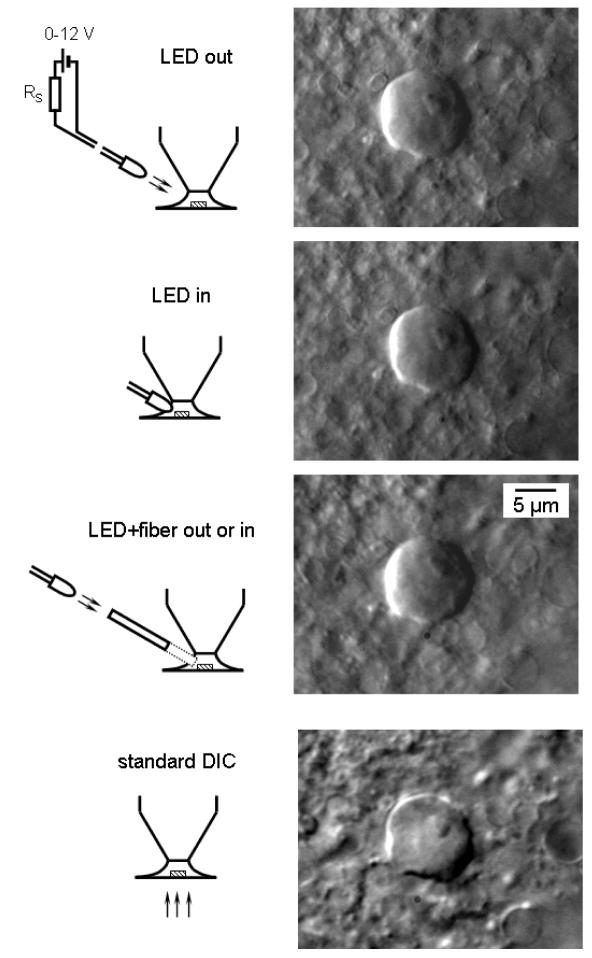
Neurons were viewed using an upright microscope (Carl Zeiss, Axioscope) with a water immersion objective (40x, 0.8 NA) with a working distance of 3.6 mm. DIC imaging was done in transmitted light using 0.9 NA condenser. In experiments with LED illumination, the upper pathway of the microscope was free; all components like the DIC prism, analyser, filters etc. were removed. Images were viewed with a high-resolution black-and-white digital CCD camera (C4742-95 Hamamatsu, Japan). All images shown in this paper were taken using this camera, but it should be noted that a simple black-and-white analogue CCD camera (KP-M2R, Hitachi Kokusai Electric, Japan) connected to a black-and-white monitor (VMM-12/3, VT, Germany) could be also employed to work with LED illumination. Images of spinal neurons and axons in Figs. 1–4 were captured using an additional 4x lens positioned between the microscope and the video camera. All illustrations represent averages of ten images done to reduce pixel noise apparent at a high magnification. The images shown in the figures were captured with standard settings of the camera and illumination intensities optimized to reduce the exposition time. Images were obtained from neuronal structures located in both superficial (0–20 μm, Fig. 1–4) and deep (up to 90 μm, Fig. 5) layers of the slice. The LED illumination circuitry consisted of three elements (Fig. 1): a LED, a battery or regulated power supply unit (0–12 V) and a series resistor (calculated according to LED specification). We have chosen LEDs with a diameter of 5 mm, possibly narrow beams (20–30°) and maximum brightness: white (11 Candela, Linrose Electronics, Plainveiw, NY), blue (470 nm, 3.5 Candela, Linrose Electronics, Plainveiw, NY) and infrared (940 nm, viewing angle 45°, RadioShack, Fort Worth, TX). In experiments with optical fibers, we used a commercially available system provided by LINOS (Germany) which included a regulated power supply unit with a white LED (Luxeon) directly coupled to a flexible bundle of fibers with a diameter of 3 mm. LEDs or the optical fiber were positioned on a manipulator to enable a fine adjustment of illumination. The angle of LED to a horizontal axis was 20–40°. Intensity of LED illumination was measured using a quantum sensor SKP 216Q with a range of 400–700 nm (Skye Instruments, Powys, UK). All measured values are presented in relation to the maximum illumination intensity of the LED considered as 100 %.
Fig. 1.
Single-cell imaging with oblique LED illumination. First three images were captured from the same neuron in a 200 μm transverse spinal cord slice using oblique LED illumination. Corresponding experimental arrangements are shown on the left of each image. Bare white LED was positioned either outside or inside the solution meniscus in recording chamber (first two images). An optical fiber was directly coupled to the white LED (the third image). Each time the focus was adjusted to provide best performance. For comparison, the bottom image was obtained with standard transmitted-light DIC optics. The neuron was located in the substantia gelatinosa (lamina II).
Fig. 4.
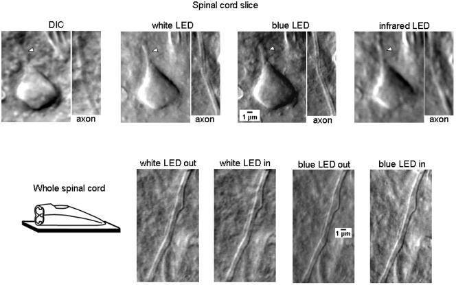
Imaging of cell processes and fine-calibre unmyelinated afferent axons in spinal cord slices and the whole spinal cord. Upper line, images of processes of a dorsal horn neuron and of primary afferent axon in the substantia gelatinosa (lamina II) viewed in a 300 μm slice using transmitted-light DIC optics or obliquely positioned white, blue (470 nm) and infrared LED (940 nm). LEDs were positioned outside the solution. The initial segment of the axon or dendrite of a dorsal horn neuron is marked by the arrowhead. Note, both the initial segment and the afferent axon cannot be clearly seen in DIC but are well resolved with white and blue LED illumination. As expected, the infrared LED provided lowest resolution because of the longest wavelength. Bottom line, images of a fine-caliber afferent fiber in the dorsal root entry zone captured in the whole spinal cord preparation using white and blue LEDs positioned inside or outside of meniscus.
Fig. 5.
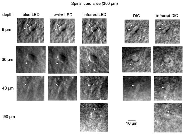
Imaging of neuronal somata as a function of depth. The somata of dorsal horn neurons (lamina II) were visualized in 300 μm spinal cord slices from 31-day-old rat using a blue LED, white LED and infrared LED as well as a standard (white light) DIC and infrared DIC optics. The depth of the imaging is shown on the left. Somata are indicated by arrowheads. All LEDs were positioned outside of solution.
2.2. Preparation and recording
15–31-day-old rats were sacrificed in accordance with the national guidelines (Direcção Geral de Veterinária, Ministério da Agricultura). Spinal cord slices of 200 or 300 μm thickness were prepared and incubated as we previously described (Melnick et al. 2004a,b). Slices were mechanically fixed in the recording chamber by a grid of nylon threads. Spinal cord blocks, the whole spinal cord and brain were prepared in a similar way with following differences. They were directly glued by cyanoacrylate adhesive to a 1 mm thick metal plate and only one cut was done using a tissue slicer (Leica VT 1000S, Germany) to create an access to gray matter. After a standard incubation procedure, the metal plate with the glued spinal cord or brain was transferred into the recording chamber where metal plate provided mechanical fixation of the preparation. When the preparation of the whole spinal cord with attached dorsal roots was positioned in the recording chamber, care was taken to avoid direct shadow imposed by roots on the cut surface. Tight-seal whole-cell recordings from spinal dorsal horn neurons were done as previously described (Safronov et al. 1997). Bath solution had a composition (in mM): NaCl 115, KCl 3, CaCl2 2, MgCl2 1, glucose 11, NaH2PO4 1, NaHCO3 25, and glucose 11 (pH 7.4 when bubbled with 95%-5% mixture of O2-CO2). The pipette solution contained (in mM): KCl 3, K-gluconate 150.5, MgCl2 1, BAPTA 1 and HEPES 10 (pH 7.3 adjusted with KOH, final [K+] was 160.5 mM). The amplifier was EPC-9 (HEKA, Lambrecht, Germany). The effective corner frequency of the low-pass filter in voltage-clamp mode was 3 kHz.
3. Results
To demonstrate the power and versatility of the technique, we used the oblique LED illumination for imaging single cells from a variety of preparations with a very different optical density: conventional thin slices of several hundred micrometers, very thick 3 mm slices glued on the top of a non-transparent for transmitted illumination plate and, finally, from the entire brain and spinal cord. First, we prepared thin 200 μm slices from spinal cord and have chosen for imaging spinal dorsal horn neurons for their relatively small size (soma diameter of about 10 μm). An image of a dorsal horn neuron obtained with a white LED positioned outside the solution is shown in Fig. 1 (LED out). The LED could be positioned 3 to 20 mm away from the surface of solution meniscus with no change in the image quality, provided that the intensity of LED illumination for more remote position was increased (see below). Although we always took care to reduce the size of solution meniscus and to ensure that light falls perpendicularly to its surface, the same resolution could be also achieved with large and non-perpendicularly oriented menisci. Insertion of the white LED into the solution did not improve resolution (Fig. 1, LED in), however, less illumination was needed in this case. High-resolution images were also captured when the LED has been coupled to an optical fiber (Fig. 1, LED + fiber out or in). As a bare LED, the fiber could be positioned outside as well as inside the bath solution without losing the image quality. For comparison, an image of the same dorsal horn neuron has been also taken in transmitted light using standard DIC optics as shown in Fig. 1 (bottom).
Using a bare white LED we studied how the necessary intensity of illumination changes with LED position. These estimations were done for images obtained in the presence and absence of an additional 4x lens. When the lens was inserted for a high-resolution imaging (Fig. 1), we fixed the camera exposition time at 50 ms. Under these conditions, 100 %, 28 % and 23 % of maximum illumination intensity were needed for the LED positioned 20 mm, 3 mm away from the meniscus and inside the solution, respectively. If the 4x lens was not used (as in Fig. 5), the exposition time was reduced to 10 ms and 75 %, 23 % and 16 % of maximum illumination intensity were sufficient for imaging with LEDs positioned 20 mm, 3 mm away from the solution and within the solution, respectively.
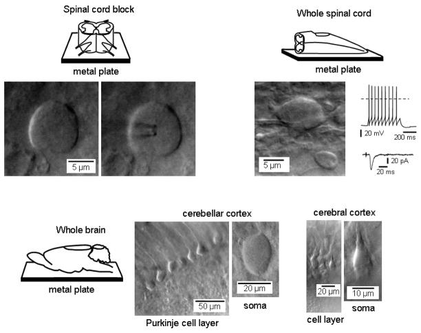
Oblique LED illumination allowed us also to obtain high-resolution images of dorsal horn neurons in 3 mm high spinal cord block glued on the top of a non-transparent metal plate, under condition where DIC optics in transmitted light could not be used (Fig. 2, upper left, transverse section). Most importantly, the technique was successful in a high resolution imaging from the whole spinal cord and the whole brain. Fig. 2 (upper right) shows a single-cell imaging from the whole spinal cord (parasagittal section). Both spinal cord preparations were cut just once by tissue slicer to provide access to the spinal gray matter. To insure that viewed neurons were in a good functional state we also recorded from them on a regular basis. Tight-seal whole-cell recordings of action potentials and post-synaptic currents were done in twenty-seven neurons (Fig. 2 upper right) and we did not find any difference in the probability of obtaining giga-seal contact under these and conventional ‘thin slice-DIC optics’ conditions. Moreover, the same technique was also successful for a high-resolution imaging of surface cells in different areas of the brain, when only a single cut was introduced to expose the surface of the entire brain (Fig. 2, bottom images).
Fig. 2.
Imaging with oblique LED illumination and patch-clamp recordings in spinal cord blocks, whole spinal cord and brain. Upper schemes show a 3 mm high spinal cord block (left) and a whole spinal cord (right) glued to opaque 1 mm metal plate for imaging. A small cut has been made through the upper surface of the spinal cord. A white LED was positioned outside the solution meniscus. Examples of single-cell images (laminae I–II) for each preparation are shown below the corresponding scheme. Right, patch-clamp recordings done from a substantia gelatinosa (lamina II) neuron identified under LED illumination in the whole spinal cord. The train of action potentials was evoked by direct injection of a 500 ms current pulse (upper trace). A postsynaptic current was evoked by the stimulation of the segmental dorsal root through a suction electrode (lower trace). Bottom images, a single cut has been made through cerebellar and cerebral cortex of the whole brain (shown schematically on the left) and cells in both regions have been imaged using LED illumination. An additional 4x lens was not used for the imaging of cerebral and cerebellar neurons.
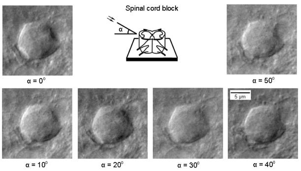
A white LED coupled to a fiber optic was used to study the effect of illumination angle on image quality in a spinal cord block. Although apparently good images were obtained with illumination angles from 0° to 50° to the horizontal axis (Fig. 3), in most cases the best performance was achieved at 20–40°. By rotating the source of illumination (or a preparation) around the vertical axis, we could also change the direction of ‘shadowing’ and select the best projection for the cell imaging (not shown).
Fig. 3.
Effect of illumination angle on LED imaging. A dorsal horn neuron (lamina II) viewed in the spinal cord blocks at varying illumination angles to a horizontal axis. Light source was a white LED directly coupled to a flexible bundle of optical fibers with a diameter of 3 mm. In most cases, best images were seen at 20–40°.
We have also tested whether oblique illumination with a bare LED could be used for imaging fine neuronal structures like axons or dendrites. Again, we have chosen substantia gelatinosa region of the spinal dorsal horn and focused on fine processes of local interneurons or fine-calibre unmyelinated primary afferent axons of C-type, both with a diameter of about 1 μm. Presumable C-type axons were identified in the axon bundles in the dorsal root entry zone. To further test the quality of imaging with the new technique, we first compared the DIC and LED images in 300 μm spinal cord slices (Fig. 4, top). Transmitted light DIC optics allowed us to view only the cell body, whereas neither the cell processes (arrowhead) nor the C-type afferent axons were clearly seen. In contrast, images obtained with white LED illumination well resolved both the cell processes and the afferent axons. In order to test whether the short-wave light can provide further improvement in resolution, we captured images with a blue LED (470 nm wavelength). Indeed, blue LED images had significantly better resolution than those obtained with a white LED (Fig. 4, top). When the LED wavelength was increased to 940 nm (infrared LED) the quality of image became much worse, indicating that the wavelength critically influences the resolution limit (Alberts et al., 2002).
In the whole spinal cord preparation, both white and blue LEDs allowed imaging fine structures, like primary afferent C-fibers (Fig. 4, bottom), with the same quality as in thin slices. The resolution with blue LED was again higher for both outside or inside positions.
To study how the quality of LED imaging changes with the depth, we prepared 300 μm spinal cord slices and compared images of soma of dorsal horn neurons obtained using a blue, white and infrared (940 nm) LEDs with those obtained using a standard DIC and infrared (780 nm) DIC optics (Fig. 5). At a depth of 6 μm, all five combinations provided good images with the best resolution achieved for a blue LED. At 30 μm, infrared LED was at advantage. At 40 μm, only the cell silhouette was seen with a blue LED, whereas an infrared LED had again the best performance. A limit for imaging was reached at a depth of 90–100 μm where only infrared LED and infrared DIC barely resolved neuronal soma. In general, a blue LED provided best resolution of fine neuronal structures in superficial 10–15 μm of tissue becoming less advantageous for deeper imaging. Resolution of white LED imaging depended on the depth in a similar manner as for standard (white light) DIC optics allowing cell viewing within 30–40 μm. Both infrared LED and infrared DIC were better for deeper imaging and were affected to the same degree with increasing depth. Images obtained with oblique LED illumination had, as a rule, a better resolution (Fig. 5).
4. Discussion
The main conclusion of this study is that oblique LED illumination enables a high-resolution single-cell imaging and patch-clamp study of neurons in slices of unlimited thickness as well as in the whole brain or spinal cord. As a source of illumination we utilized super bright LEDs suitable for the technique because of small size and high brightness achieved with a low power when no heat sink was required. Under these conditions, we resolved fine axons and dendrites with a diameter of about 1 μm. High quality images can be obtained either with bare LEDs or LEDs coupled to optical fibres. The source of illumination can be positioned out- or inside the bath solution. The outside location appears to be more convenient, since the LED did not occupy space in the recording chamber and did not interfere with recording pipettes. Although a white LED is more convenient to view slices by eyes, a blue LED should be used instead if a higher resolution is required. If imaging of deeper cell layers were needed, it is advisable to use an infrared LED. In an experiment, one can position a white, blue and infrared LEDs on one holder and use them depending on the depth of the region of interest. Such configuration allows a high resolution imaging of superficial neuronal structures like axons and dendrites with a deep cell body imaging.
We assume that oblique LED illumination provides considerably higher resolution of superficial structures than conventional DIC optics for the following reasons. In DIC imaging, the scattering of the light passing through the slice lowers system resolution. The utility of the technique is limited therefore by thickness of the preparation and its optical density. One can reduce scattering by using a long-wave infrared light (780 nm) instead of a visible light (MacVicar 1984; Dodt and Zieglgansberger 1990; Stuart et al. 1993, Nashmi et al. 2002). In this case, however, the increase in wavelength unavoidably lowers the resolving power of the system, in agreement with the basic principle of microscopy (Alberts et al. 2002). Therefore, in tissue slices DIC optics cannot approach its maximum limit of resolution regardless of the wavelength of the transmitted light. In contrast, oblique LED illumination gives images in reflected light component which has much less scattering. Shortening the wavelength to 470 nm by using a blue LED further increases resolution. Thus, oblique LED illumination microscopy can reach a higher resolution, approaching its limit imposed by the numerical aperture of the objective and light wavelength. Such high resolution is valid for thin slices, tissue blocks of unlimited thickness and optical density, or entire brain. In addition, the short-wave blue light is also better reflected from the tissue surface that brings further advantages for the reflected light imaging.
Furthermore, the oblique LED illumination provides high resolution imaging of cells located above opaque structures, under conditions when conventional DIC optics cannot be used. Finally, commercially available low price LEDs with a life time of hundred thousand hours represent an affordable alternative to conventional DIC optics. Taken together, the LED-based imaging is a powerful new tool for single-cell imaging and visually controlled recordings from neurons in their natural networks either in the whole brain or spinal cord.
Acknowledgments
We thank Dr. Joachim Guendel, Dr. Craig Jahr and Dr. Larry Trussell for discussion and helpful suggestions and Mr. Norbert Henze (LINOS) for providing LED-coupled optical fibers. Supported by the FCT grant (to B.V.S), NIH grant NS027037 (Thomas Soderling and V.A.D.) and Medical Research Foundation grant (V.A.D.).
Footnotes
Publisher's Disclaimer: This is a PDF file of an unedited manuscript that has been accepted for publication. As a service to our customers we are providing this early version of the manuscript. The manuscript will undergo copyediting, typesetting, and review of the resulting proof before it is published in its final citable form. Please note that during the production process errors may be discovered which could affect the content, and all legal disclaimers that apply to the journal pertain.
References
- Alberts B, Johnson A, Lewis J, Raff M, Roberts K, Walter P. Molecular biology of the cell. 4. Garland Science; New York: 2002. p. 552. [Google Scholar]
- Dodt HU, Zieglgansberger W. Visualizing unstained neurons in living brain slices by infrared DIC-videomicroscopy. Brain Res. 1990;537:333–36. doi: 10.1016/0006-8993(90)90380-t. [DOI] [PubMed] [Google Scholar]
- Edwards FA, Konnerth A, Sakmann B, Takahashi T. A thin slice preparation for patch clamp recordings from neurones of the mammalian central nervous system. Pflugers Arch. 1989;414:600–12. doi: 10.1007/BF00580998. [DOI] [PubMed] [Google Scholar]
- MacVicar BA. Infrared video microscopy to visualize neurons in the in vitro brain slice preparation. J Neurosci Meth. 1984;12:133–9. doi: 10.1016/0165-0270(84)90012-8. [DOI] [PubMed] [Google Scholar]
- Melnick IV, Santos SFA, Szokol K, Szucs P, Safronov BV. Ionic basics of tonic firing in spinal substantia gelatinosa neurons of rat. J Neurophysiol. 2004a;91:646–55. doi: 10.1152/jn.00883.2003. [DOI] [PubMed] [Google Scholar]
- Melnick IV, Santos SFA, Safronov BV. Mechanism of spike frequency adaptation in substantia gelatinosa neurones of rat. J Physiol. 2004b;559:383–95. doi: 10.1113/jphysiol.2004.066415. [DOI] [PMC free article] [PubMed] [Google Scholar]
- Nashmi R, Velumian AA, Chung I, Zhang L, Agrawal SK, Fehlings MG. Patch-clamp recordings from white matter glia in thin longitudinal slices of adult rat spinal cord. J Neurosci Meth. 2002;117:159–66. doi: 10.1016/s0165-0270(02)00096-1. [DOI] [PubMed] [Google Scholar]
- Safronov BV, Wolff M, Vogel W. Functional distribution of three types of Na+ channel on soma and processes of dorsal horn neurones of rat spinal cord. J Physiol. 1997;503:371–85. doi: 10.1111/j.1469-7793.1997.371bh.x. [DOI] [PMC free article] [PubMed] [Google Scholar]
- Stuart GL, Dodt HU, Sakmann B. Patch-clamp recordings from the soma and dendrites of neurons in brain slices using infrared video microscopy. Pflugers Arch. 1993;423:511–8. doi: 10.1007/BF00374949. [DOI] [PubMed] [Google Scholar]


