Abstract
Quadrupole magnetic field-flow fractionation (QMgFFF) is a separation and characterization technique for magnetic nanoparticles such as those used for cell labeling and for targeted drug therapy. A helical separation channel is used to efficiently exploit the quadrupole magnetic field. The fluid and sample components therefore have angular and longitudinal components to their motion in the thin annular space occupied by the helical channel. The retention ratio is defined as the ratio of the times for non retained and a retained material to pass through the channel. Equations are derived for the respective angular and longitudinal components to retention ratio.
Keywords: Field-flow fractionation, magnetic field-flow fractionation, MgFFF, magnetic nanoparticles, nanoparticle characterization, quadrupole magnetic field, helical channel
The field-flow fractionation (FFF) techniques are for the separation and characterization of particulate and macromolecular materials suspended or dissolved in a liquid medium. They are similar to chromatography in that different components of a small sample elute from a separation channel at different times [1]. Chromatography exploits differences in partition between mobile and stationary phases to separate sample components as they are carried along a column, but FFF separation is achieved within the flowing mobile phase and does not utilize a stationary phase. The separation channel optimally has a uniform thickness and a high aspect ratio, i.e., it is much thinner than it is broad. The fluid velocity profile is therefore parabolic, or close to parabolic, with the fastest velocity close to the center and zero velocity at the walls. The small perturbation due to the viscous drag of the side-walls may be ignored for a channel of high aspect ratio. A field of some type is applied across the channel thickness, perpendicular to the direction of fluid flow. The materials to be separated (we restrict our consideration to submicron particles in this work) interact with the field and are driven toward one of the walls, known as the accumulation wall. The resulting increase in concentration adjacent to the accumulation wall is opposed by Brownian diffusion, and dynamic steady-state distributions are approached where the concentration of each species is highest adjacent to the wall and decays exponentially away from the wall. Furthermore, the rate of exponential decay is related to the strength of the interaction with the field, so that particles that interact strongly occupy thin zones close to the wall, whereas those that interact less strongly occupy more diffuse zones. It is important to point out that the approach to steady-state occurs very quickly in the thin channel because of the relatively small migration distances involved (typically 250 μm, but may be less). Because a steady-state zone occupies only a fraction of the channel thickness, it follows that there is also a very rapid exchange of particles within the thickness of a zone. This means that a collection of identical particles will be carried along the channel length as a coherent band as they all sample different streamline velocities equally. Strongly interacting particles are confined to slowly moving streamlines close to the wall and have a relatively long elution time. Particles that occupy more diffuse zones are able to sample faster moving streamlines as well as those close to the wall, and elute more quickly. Separation according to strength of interaction with the applied field is thereby obtained.
Important aspects of this optimal implementation of the FFF separation mechanism are the thin channel of uniform thickness across its breadth, and the transverse field applied uniformly across the channel breadth. Quadrupole magnetic field-flow fractionation (QMgFFF) uses a thin helical channel mounted in an axisymmetric magnetic field. Inside the aperture of the quadrupole, the field strength increases radially from the axis. The gradient in field strength is constant and directed radially outward from the axis. Magnetization of the particulate sample is induced by the applied magnetic field and the particles are driven toward the outer channel wall by their interaction with the field gradient. The helical channel has a number of advantages over a full annular channel. An annular channel requires the carrier fluid and sample be distributed uniformly around the annulus at the inlet and collected uniformly around the annulus at the outlet. This is not easily achieved in practice. Multiple inlets and outlets, distributed around the annulus are required. Partial or complete blockage of any of the multiple inlets or outlets would disrupt flow patterns and contribute to band-spreading and loss of resolution. Any variation in field gradient around the circumference of the annular channel would result in variation of elution times, again leading to loss of resolution. It is also difficult to fabricate and maintain a perfectly uniform, thin annular channel. Variations in thickness around the circumference would offer variations in resistance to flow; in fact, mean velocity varies with the square of the channel thickness for a given pressure drop. Again, the net result would be a loss of resolution. On the other hand, a helical channel has a single inlet and a single outlet, the helical path forces all particles to sample any circumferential variations in field gradient, and the approach taken for channel assembly tends to reduce variations in channel thickness. The helical channel is machined into the surface of a polyoxymethylene rod (Delrin™ from DuPont) that fits tightly into an internally polished stainless steel tube [2–4]. It is therefore self-centering throughout the length of the tube. The helical nature of the QMgFFF channel does, however, require a careful consideration of the fluid velocity profile, as well as the influence of any secondary flow effects due to channel curvature and torsion. This work is concerned with only the effect of fluid velocity profile on sample elution.
QMgFFF has been used to characterize magnetic nanoparticles such as those used for cell labeling and for targeted drug therapy. These particles consist of a magnetic component with biocompatible coatings carrying antibodies or therapeutic drugs. The coatings stabilize the materials in suspension and also reduce the magnetic dipole-dipole interactions between particles in a magnetic field. The force exerted on a single magnetic particle due to its interaction with a magnetic field gradient is given by
| (1) |
where Vm is the volume of the magnetized component of the particle, M is the magnetization of this component, and ∇B is the gradient in magnetic field strength B. The particle coating, any antibodies or drugs associated with the particle, and the suspending fluid are all assumed to be paramagnetic and will have insignificant influence on the overall force. In the channel, the particles will be driven across the channel thickness toward the so-called accumulation wall (the outer wall) at a velocity u given by
| (2) |
in which f is the friction coefficient given by 3πηdp where η is the fluid viscosity and dp is the hydrodynamic diameter of the particle. This creates a gradient in concentration c that is opposed by Brownian diffusion. At every point across the channel thickness, the net radial flux Jr toward the (outer) accumulation wall is given by
| (3) |
In this equation D is the particle diffusion coefficient, c is the local concentration, and dc/dr is the local gradient in concentration in the radial direction. In the thin channel, a steady state distribution is quickly approached and Jr is then effectively zero at every point across the channel thickness, so that
| (4) |
The second form on the right of eq (4) is obtained by the substitution of D by kT/f = kT/3πηdp. The friction coefficient cancels and the steady state concentration profile is therefore independent of both the hydrodynamic diameter of the particles and the viscosity of the suspending fluid. It is therefore only the force on the particles due to the interaction of their magnetic component with the field gradient that determines the concentration profile. The steady state profile is obtained by solving the integral equation
| (5) |
in which c0 is the particle concentration adjacent to the accumulation wall, ro is the radius of the (outer) accumulation wall, and the new variable of integration ρ is the dimensionless radial distance r/ro, so that ρ = 1 when r = ro. The force Fm is a function of the magnetization of the magnetic component (see eq (1)) which is generally a function of the local field strength B. However, the particles are confined to a thin annulus across which the field strength will vary by, typically, a few percent. Furthermore, the particles are driven into a thin layer within the annulus, adjacent to the (outer) accumulation wall. The force on the particles may therefore be approximated by that at the outer channel wall radius. Solution of eq (5) then gives
| (6) |
where
| (7) |
so that λ is the ratio of thermal energy kT to the work Wo required to drive a particle a distance equal to the channel thickness w (= ro − ri) against the force experienced by the particle at the accumulation wall. The variable ξ introduced in eq (6) is equal to x/w = (1−ρ)/(1−ρi), where x is the distance measured away from the accumulation wall toward the axis of the annular channel. The parameter ρi is the ratio of inner wall radius ri to that of the outer wall, ρi = ri/ro. To a good approximation, the concentration decays exponentially away from the accumulation wall.
In FFF, the retention time, or alternatively, the elution time, may be given in terms of the retention ratio R which is defined as the ratio of the time t0 for a non-retained material to pass through the channel to that of the retained material tr. Alternatively, R may be defined as the ratio of the time for a material to pass through the channel when no field is applied to the time taken when the field is applied. This is equivalent to the ratio of the velocities of the retained material to a non-retained material:
| (8) |
where the angle-brackets indicate the mean of the enclosed quantity over the channel cross section. The velocity of the non-retained material is therefore assumed to be equal to the mean fluid velocity in a cross section of the channel, and the retained material has a velocity that weights local velocity by local particle concentration, so that vp = <cv>/<c>. It must be remembered that in the thin FFF channel the dynamic exchange of particle positions within the steady-state concentration profile allows them to sample fluid velocities across the channel thickness. In the parallel-plate systems, the time spent at any position across the velocity profile is proportional to local steady-state concentration. The influence of the side-walls is commonly ignored and the mean is taken across channel thickness, so that, for example
| (9) |
The fluid velocity for a helical channel may be considered to be, to a first approximation, the summation of two orthogonal components: the longitudinal and the angular velocity components. The longitudinal component is in the direction parallel to the axis of the annulus, and the angular component circles around the axis. The two components of sample velocity may be given in terms of the two fluid velocity components and the two respective retention ratios. The retention ratio Rz for longitudinal flow in an annular channel is given by
| (10) |
where vzp is the sample velocity along the length of the annulus and <vz> is the mean fluid velocity along the length of the annulus. For the annular channel, the mean concentration, for example, over the channel cross section takes the following form
| (11) |
Solving the integral in the denominator and changing the variable of integration in the numerator to ξ, results in
| (12) |
The retention ratio for the angular component to flow is given by
| (13) |
where ωp is the angular component to sample velocity and <ω> is the mean angular fluid velocity.
Analytical solutions for the longitudinal vz, angular ω, and azimuthal vθ velocities of a Newtonian fluid in an annulus may be obtained by solution of the relevant Navier-Stokes equations [5]. For purely longitudinal, steady fluid flow (ignoring the influence of gravity), we have
| (14) |
in which ∂p/∂z is the pressure drop in the z-direction, and η is the fluid viscosity. Double integration, and imposing the no-slip boundary conditions at the walls, results in
| (15) |
where Δp is the pressure drop along the annulus and L is the length of the annulus. Determination of <vz> by integration of vz over the annular cross-section and dividing by the cross-sectional area (analogous to eq (11)) yields
| (16) |
Making the appropriate substitution into eq (15) gives the final result
| (17) |
in which
| (18) |
This result has been presented earlier by us [6–9] and by Davis and Giddings [10]. For purely azimuthal, steady fluid flow, the relevant Navier-Stokes equation may be written as
| (19) |
and since vθ = rω, we can write
| (20) |
Following the same approach as for vz, we obtain
| (21) |
in which
| (22) |
The azimuthal velocity is obtained in the same manner from the starting point of eq (19):
| (23) |
in which
| (24) |
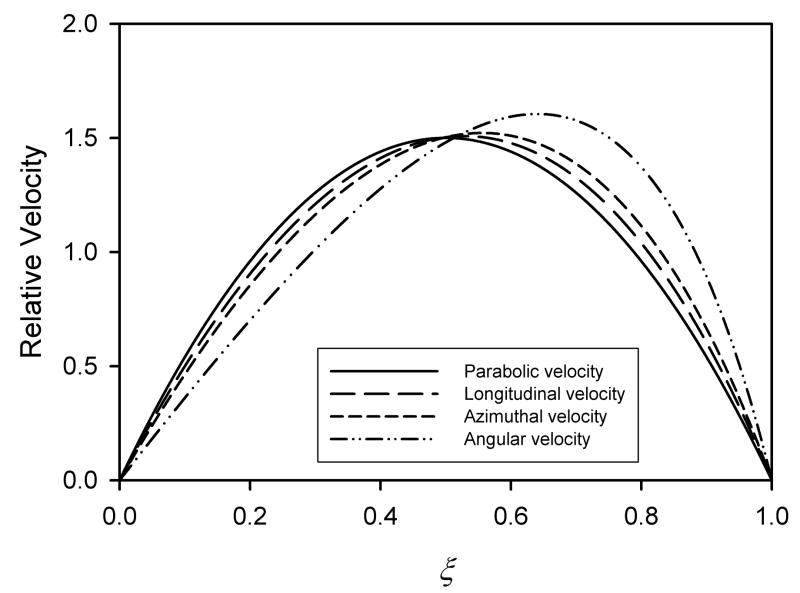
This result may be shown to be equivalent to that derived by Davis [11]. Figure 1 shows a comparison of the three normalized velocity profiles vz/<vz>, ω/<ω>, and vθ/<vθ> with the parabolic profile that is obtained for a parallel-plate channel. The parameter ρi was set to 0.5 to better illustrate the differences. Typically, annular FFF channels have ρi that are greater than 0.95 for which the differences between the curves would be less apparent.
Figure 1.
Comparison of the normalized velocity profiles vz/<vz>, vθ/<vθ>, and ω/<ω> for the annular channel with the ratio ρi of inner to outer radii of 0.5, and v/<v> for the parallel-plate channel.
The forms of eqs (17) and (21) preclude the derivation of analytical solutions for Rz and Rω. There are other FFF techniques where the velocity profile deviates from parabolic and for which an analytical solution for R cannot be derived. For example, in thermal FFF a temperature gradient is maintained across the channel thickness and this leads to a distortion of the velocity profile because of the effect of temperature on fluid viscosity. A first order correction has been proposed [12,13] to account for this distortion of the velocity profile that allows derivation of a good analytical approximation for R. The profile is approximated by the cubic equation in ξ
| (25) |
In this equation, υ is an adjustable parameter that allows for deviation of the shear rate at the accumulation wall from that of the isoviscous, parabolic profile. The equation also has the required property of predicting zero velocity at each of the walls. The region close to the accumulation wall is important for predicting particle elution and the parameter is adjusted so that 6<v>(1+υ)/w is a good fit to the true shear rate at the wall. This approach may be adapted to the velocity profiles for an annular channel. In this case, a second parameter μ must be included that is a function of the ratio ρi of the inner to the outer radii. The cubic equation has the general form:
| (26) |
This has the same adjustable parameter υ for the shear rate at the accumulation wall. The equation also retains the required property of giving zero velocity at each of the walls. The value for μ is obtained from the required identity (recalling eq (12)):
| (27) |
Solution of this equation reveals that, for all υ ≠ 0, μ is given by
| (28) |
The parallel-plate system corresponds to ρi = 1 in which case μ = 3, and eq (26) becomes consistent with the parallel-plate solution given by eq (25). At the other extreme where ρi approaches zero, μ is seen to approach 3.5. The parameter μ does not therefore vary over a wide numerical range.
We can obtain cubic approximations to each of the velocity profiles in the annulus as follows. For the longitudinal velocity profile, we have
| (29) |
The parameter υz must be adjusted to equate 6<vz>(1+υz)/w with the accurate shear rate at the accumulation wall (consistent with eq (17)), which is the outer wall for magnetized particles. The result is given by
| (30) |
The same exercise may be carried out for the cubic approximations for angular and azimuthal velocity profiles. These results are given by
| (31) |
in which
| (32) |
and
| (33) |
in which
| (34) |
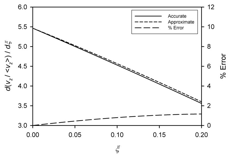
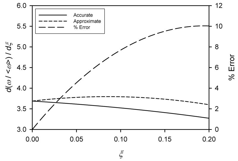
Figures 2a, b, and c show the plots of the first differentials of the normalized profiles with respect to ξ for the true profiles and the cubic approximations to the profiles. Also shown are the % errors of the first differentials of the cubic approximations compared to thoseof the true profiles. A ratio ρi of 0.5 was chosen, as for Figure 1, in order to show significant deviation of the approximate equations from the true values. It may be seen that the first derivative of the cubic approximation for angular velocity is significantly worse than those for longitudinal and azimuthal velocities. This is simply because the angular velocity profile deviates further from parabolic than the other two, as shown in Figure 1.
Figure 2.
The first derivative of the normalized fluid velocity profiles with respect to ξ in the region of the accumulation (outer) wall. The approximate curves are based on the respective cubic approximations to velocity profiles. The curves of % errors refer to the right-hand axes. a) Longitudinal velocity, b) Angular velocity, c) Azimuthal velocity. In all cases ρi = 0.5 in order to better illustrate the relative goodness of the fits.
We are now in a position to derive approximate expressions for the longitudinal and angular retention ratios. For the longitudinal retention ratio
| (35) |
Substitution for ρi using a rearrangement of eq (28), and for c and vz using eqs (6) and (29), respectively, yields the solution
| (36) |
For material that is acceptably well retained where λ is less than about 0.15, the terms in exp(−1/λ) are insignificant, and the expression reduces to
| (37) |
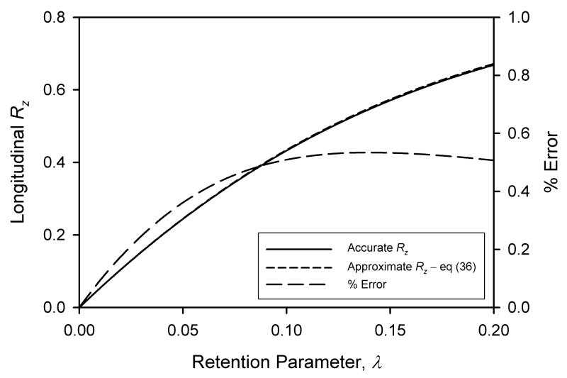
Figure 3a shows the comparison of the true longitudinal retention ratio calculated by numerical integrations involving the true velocity profile given by eq (17) (full line) with that given by eq (36) (short-dashed line). A ratio of inner to outer channel radii ρi of 0.5 was selected to show a visible error. The percentage difference is shown by the longer-dashed line and this refers to the right hand axis, and is seen to be less than 0.6% in the range of λ up to 0.2.
Figure 3.
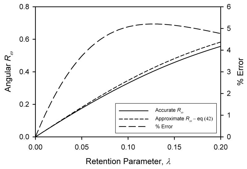
Comparison of numerically determined retention ratios based on true velocity profiles with results based on cubic approximations to velocity profiles. a) Longitudinal retention ratio Rz, approximate result by eq (36); b) Angular retention ratio Rω, approximate result by eq (42); c) Angular retention ratio Rω, approximate result by eq (46). The curves of % errors refer to the right-hand axes. In all cases ρi = 0.5.
As a check on consistency, it may be shown that if μ is set to 3 in eq (36), the equation does indeed reduce to the expected parallel-plate solution with first order correction for deviation of the velocity profile from parabolic, given by [12,13]
| (38) |
in which R2 is the retention ratio for an ideal parabolic velocity profile:
| (39) |
Similarly, when μ in eq (37) is set to 3, the equation reduces to the form given by eq (38), but with R2 given by the approximate parallel-plate solution for retention ratio, accurate to better than 0.4% for λ < 0.15:
| (40) |
In the case of the angular retention ratio, we take a similar initial approach:
| (41) |
Substitution using eqs (6), (28), and (33), yields the following solution:
| (42) |
This has exactly the same form as eq (36), but incorporates the parameter υω rather than υz. We can modify our approach by noting that the azimuthal velocity vθ is related to the angular velocity ω as follows
| (43) |
and we can advantageously substitute for ρω in eq (41). It is advantageous because the cubic approximation for vθ was found to be better than that for ω. It can also be shown that <vθ> is related to <ω> by
| (44) |
Making these two substitutions into eq (41), changing the variable of integration to ξ, and substituting for ρi using a rearrangement of eq (28) results in
| (45) |
and on substituting eq (6) for c and eq (33) for vθ gives the solution
| (46) |
Again, for relatively well retained material where λ is less than about 0.15, this reduces to
| (47) |
Figures 3b and c show the comparison of the results based on eqs (42) and (46), respectively, with the true angular retention ratio based on numerical integrations involving the true angular velocity profile given by eq (21). As expected, the result given by eq (46), obtained by consideration of the better cubic approximation to the azimuthal velocity profile, is a better match to the true retention ratio. The result given by eq (42) deviates from the true retention ratio by over 5% at λ around 0.1, whereas eq (46) deviates by only about 1.2%.
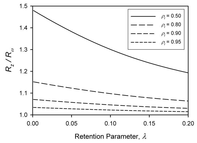
The eqs (36) and (46) have been shown to be good approximations for Rz and Rω, respectively. It is interesting to note that for a given value for ρi and any given λ, the magnitudes of the two retention ratios differ; Rz is generally larger than Rω. The consequence of this is that a sample zone will not migrate directly along the helical path of the channel, but will tend to migrate at some angle to this direction. Figure 4 shows plots of the ratio Rz/Rω as functions of λ for different values of the ratio ρi. Numerical calculations of the retention ratios were performed using the true velocity profiles. The ratio increases with ρi, so that when ρi = 0.5 the ratio Rz/Rω approaches almost 1.5 at small λ. Such a great difference between the retention ratios could interfere with the FFF separation mechanism. The sample particles would be driven quite strongly toward one of the side walls during elution (the lower side wall when the channel is arranged vertically with downward flow). This would result in a build-up of concentration close to the side wall which could lead to overloading effects (particle-particle interactions), but would place a significant fraction of the sample in the region of the channel where fluid velocities are retarded by the viscous drag of the side wall. Fortunately, for typical helical FFF channels, the value for ρi exceeds 0.95. For example, the channel used in our most recent work [4] had a nominal thickness of 250 μm and an outer wall radius of 0.743 cm, so that ρi = 0.966. For this value of ρi, the ratio of Rz/Rω approaches a maximum of only 1.023 at small λ. We can conclude that this phenomenon would not be expected to be problematic for the typical helical FFF channel.
Figure 4.
Ratios of Rz/Rω as functions of retention parameter λ. for ρi of 0.5, 0.8, 0.9, and 0.95. Numerical solutions for Rz and Rω were obtained using the true velocity profiles.
Acknowledgments
This work was supported by grants CTS-0125657 from the National Science Foundation and R01 CA62349 from the National Institutes of Health.
Footnotes
Publisher's Disclaimer: This is a PDF file of an unedited manuscript that has been accepted for publication. As a service to our customers we are providing this early version of the manuscript. The manuscript will undergo copyediting, typesetting, and review of the resulting proof before it is published in its final citable form. Please note that during the production process errors may be discovered which could affect the content, and all legal disclaimers that apply to the journal pertain.
References
- 1.Giddings JC. Science. 1993;260:1456. doi: 10.1126/science.8502990. [DOI] [PubMed] [Google Scholar]
- 2.Carpino F, Moore LR, Chalmers JJ, et al. J Phys: Conf Ser. 2005;17:174. [Google Scholar]
- 3.Carpino F, Moore LR, Zborowski M, et al. J Magn Magn Mater. 2005;293:546. [Google Scholar]
- 4.Carpino F, Zborowski M, Williams PS. J Magn Magn Mater. 2007;311:383. doi: 10.1016/j.jmmm.2009.02.065. [DOI] [PMC free article] [PubMed] [Google Scholar]
- 5.Bird RB, Stewart WE, Lightfoot EN. Transport Phenomena. 2. John Wiley & Sons; New York, NY: 2007. [Google Scholar]
- 6.Zborowski M, Moore LR, Williams PS, Chalmers JJ. Sep Sci Technol. 2002;37:3611. [Google Scholar]
- 7.Williams PS, Moore LR, Chalmers JJ, Zborowski M. Anal Chem. 2003;75:1365. doi: 10.1021/ac020649h. [DOI] [PubMed] [Google Scholar]
- 8.Williams PS, Decker K, Nakamura M, et al. Anal Chem. 2003;75:6687. doi: 10.1021/ac030152n. [DOI] [PubMed] [Google Scholar]
- 9.Jing Y, Moore LR, Williams PS, et al. Biotechnol Bioeng. 2007;96:1139. doi: 10.1002/bit.21202. [DOI] [PubMed] [Google Scholar]
- 10.Davis JM, Giddings JC. J Phys Chem. 1985;89:3398. [Google Scholar]
- 11.Davis JM. Anal Chem. 1986;58:161. [Google Scholar]
- 12.Martin M, Giddings JC. J Phys Chem. 1981;85:727. [Google Scholar]
- 13.Gunderson JJ, Caldwell KD, Giddings JC. Sep Sci Technol. 1984;19:667. [Google Scholar]


