Abstract
We have prepared conductive core-sheath nanofibers via a combination of electrospinning and aqueous polymerization. Specifically, nanofibers electrospun from poly(ε-caprolactone) (PCL) and poly(L-lactide) (PLA) were employed as templates to generate uniform sheaths of polypyrrole (PPy) via in situ polymerization. These conductive core-sheath nanofibers offer a unique system for studying the synergistic effect of different cues on neurite outgrowth in vitro. We found that explanted dorsal root ganglia (DRG) adhered well to the conductive core-sheath nanofibers and generated neurites across the surface when there was a nerve growth factor in the medium. Furthermore, the neurites could be oriented along one direction and enhanced by 82% in terms of maximum length when uniaxially aligned conductive core-sheath nanofibers are compared with their random counterparts. Electrical stimulation, when applied through the mats of conductive core-sheath nanofibers, was found to further increase the maximum length of neurite for random and aligned samples by 83% and 47%, respectively, relative to the controls without electrical stimulation. Combined together, these results suggest the potential use of the conductive core-sheath nanofibers as scaffolds in applications such as neural tissue engineering.
1. Introduction
Simultaneous presentation of biochemical, topographic, and electrical cues represents the ultimate goal for neural tissue engineering.[1,2] Most of the studies, however, have only examined the separate effect of topographic cue, electrical stimulation, or a combination of biochemical and topographic cues on neurite extension. Martin et al., Mey et al. and Colello et al. demonstrated that aligned electrospun nanofibers as topographic cues could specify the direction of DRG neurite growth and even guide axonal growth and glial cell migration.[3–5] Recently, Xia et al. reported that embryonic stem cells could differentiate into neural lineages on the electrospun PCL fibers and that aligned fibers as topographic cues could enhance the neurite extension and direct the neurite outgrowth better than random fibers.[6] In an early report, Langer et al. demonstrated that the electrical stimulation from the application of an external electrical field through a PPy film could significantly improve neurite extension from cultured neurons in vitro.[7] Li et al. investigated the synergistic effect of topographic and biochemical cues for nerve tissue regeneration where the surface of aligned electrospun nanofiber mat was derivatized with extracellular matrix (ECM) proteins and neurotrophic factors.[8] Leong et al. reported that aligned poly(ε-caprolactone-co-ethyl ethylene phosphate) (PCLEEP) nanofibers loaded with a glia cell line-derived neurotrophic factor (GDNF) showed a sustained release of protein for up to two months in vitro and that aligned nanofibers loaded with such proteins had a positive effect on functional recovery following peripheral nerve injury.[9]
Despite these reports, very few attempts have been employed to address the synergistic effect of electrical and topographical cues on the guidance and extension of neurites. Schmidt et al. fabricated PPy microchannels on the indium tin oxide (ITO)-coated slides by e-beam lithography and electropolymerization and then investigated how embryonic rat hippocampal cells responded to a combination of electrical and topographical cues.[10] They have studied PPy microchannels of 1 and 2 µm in width and the guidance effect of neurite outgrowth was not satisfactory due to the insufficient spatial resolution. Jones and Dong have prepared submicron, coaxial fibers by depositing PPy on poly(methyl methacrylate) (PMMA) fibers albeit the core-sheath fibers were not applied to the study of neurite outgrowth.[11] In addition, PMMA is a non-biodegradable polymer, making it less attractive for in vivo neural tissue engineering.
In the current work, we present a new type of scaffold, comprised of conductive core-sheath nanofibers prepared via in situ polymerization of pyrrole on electrospun PCL or PLA nanofibers, for investigating the synergistic effect of topographic cue and electrical stimulation on axonal regeneration from cultured neuronal populations as a way of exploring their potential application in neural tissue engineering. It is expected that the conductive PCL-PPy or PLA-PPy core-sheath nanofibers will provide a unique platform for investigating how neurites grow and extend under the influence of a combination of different cues. Simultaneous presentation of different cues may also provide a more effective method for promoting nerve regeneration and functional recovery. We chose PCL and PLA as the core materials due to their biocompatibility, slow degradation rate, ease of processing, and demonstrated use in neural tissue engineering.[3,12–14] We chose PPy for the sheath because of its widespread use in neural prostheses owing to its biocompatibility, easy manipulation, good stability, and high electrical conductivity.[7,15–17] Other studies have also demonstrated the use of PPy as a carrier for delivering drugs, nerve growth factors, and other extracellular proteins to enhance neurite outgrowth/extension or nerve regeneration via controlled release.[15,16,18,19] Although PPy is considered non-biodegradable and might remain in tissue for a relatively long period of time, its structure could be modified to make the polymer biodegradable.[20] Since we used PPy as a thin coating on biodegradable nanofibers, it is feasible to substantially reduce the amount of PPy contained in a nerve conduit used for in vivo applications. The fabrication technique developed in the present work for producing conductive core-sheath nanofibers also offers a major advantage over previously demonstrated methods in that it can be conducted in aqueous solution under ambient conditions.[21–26] From the perspective of biomedical applications such as tissue engineering, such mild operation conditions represent a very attractive attribute.
2. Results and discussion
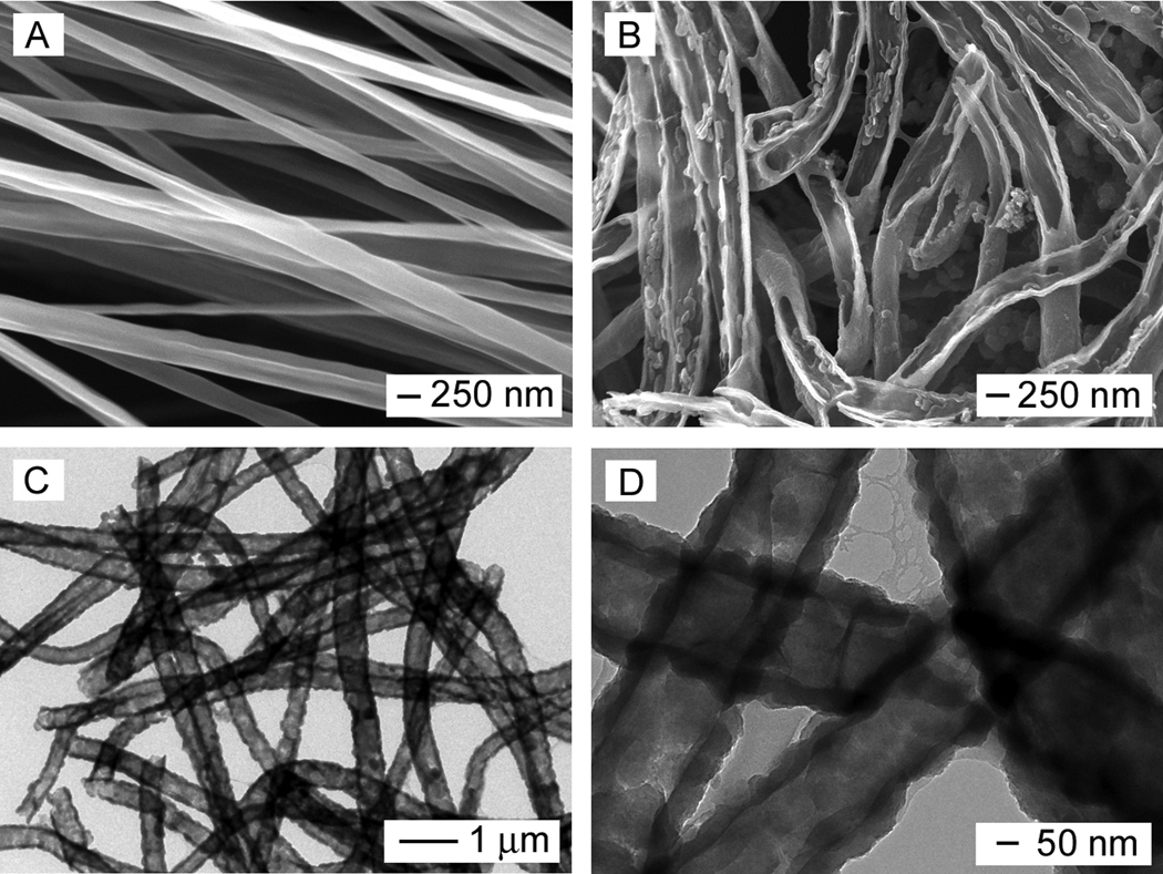
The electrospinning setup for fabricating the nanofibers is similar to what we used in our previous studies.[27,28] The in situ polymerization reaction for PPy typically involved the use of Fe3+ as an oxidant and Cl− as a dopant. In order to reveal the core-sheath structure after in situ polymerization, the nanofibers were soaked in dichloromethane (DCM) for 24 h to dissolve the cores, followed by washing several times with DCM. Figure 1A shows scanning electron microscopy (SEM) image of PCL nanofibers prepared by electrospinning. The fibers had an average diameter around 220 ± 36 nm, together with a smooth surface. Figure 1B shows SEM image of PPy nanotubes after extraction of the PCL cores by DCM. Figure 1, C and D, shows transmission electron microscopy (TEM) images of the PPy nanotubes. It can be seen that a tubular structure was indeed formed after dissolution of the PCL with DCM. The TEM images also clearly indicate the uniformity of PCL nanofibers in the core, as well as the uniformity and continuity of the PPy sheath. The PPy tubes had an outer diameter of approximately 320 ± 44 nm, revealing a PPy coating of 50 ± 3 nm thick on the surface of each PCL nanofiber. Theoretically, the C/N and C/O weight ratio of PPy and PCL are nearly 3.43 and 2.25, respectively, according to the elemental compositions of the polymers. Energy-dispersive X-ray spectroscopy (EDX) analysis of conductive PCL-PPy core-sheath nanofibers yielded a composition of C (74.94%), N (14.44%), and O (10.60%). The existence of large amount of N indicates the formation of PPy.
Figure 1.
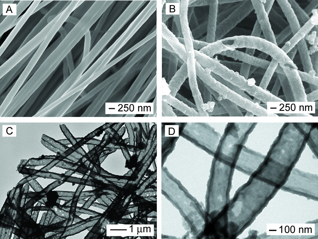
(A, B) SEM images of PCL nanofibers and PPy nanotubes, respectively; and (C, D) TEM images of the PPy nanotubes. The nanotubes were obtained by soaking the PCL-PPy core-sheath nanofibers in DCM to selectively remove the cores. The polymerization was conducted with Fe3+ as an oxidant and Cl− as a dopant.
We also demonstrated the use of electrospun PLA nanofibers as templates for generating the conductive, core-sheath nanofibers. Figure 2A shows SEM image of the PLA nanofibers, which had an average diameter of 200 ± 34 nm. Figure 2B shows SEM image of PPy nanotubes after the PLA cores had been extracted by soaking the sample in DCM. The nanotubes were broken to reveal the inside by briefly sonicating the sample. Figure 2, C and D, shows TEM images of the same sample; the PPy nanotubes had an outer diameter and a wall thickness of around 300 ± 48 nm and 50 ± 9 nm, respectively. However, comparing the TEM image in Figure 1D and Figure 2D, it is clear that the PPy sheath deposited on the PCL nanofiber was much smoother than that on the PLA nanofiber. This difference could be attributed to different molecular structures of PLA and PCL. We suspect that the extra methyl group on the side chain of PLA might make the surface of this polymer less wettable by PPy monomer than the surface of PCL. As a result, the PPy coating on PCL was smoother (due to smaller grain size) than on PLA nanofibers.
Figure 2.
(A, B) SEM images of PLA nanofibers and PPy nanotubes, respectively; and (C, D) TEM images of the PPy nanotubes. The PPy nanotubes were produced by soaking the PLA-PPy core-sheath nanofibers in DCM to selectively remove the PLA cores. The polymerization was conducted with Fe3+ as an oxidant and Cl− as a dopant.
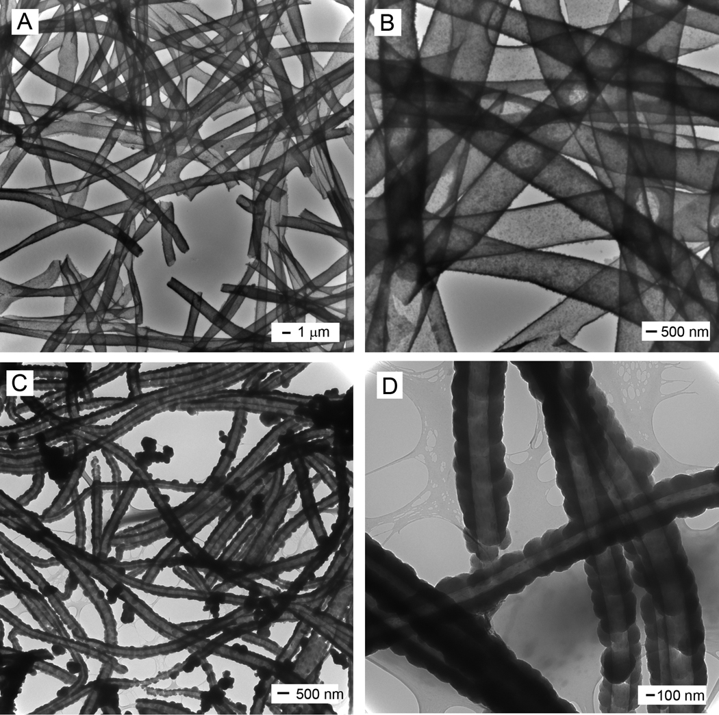
We further examined the effects of different pairs of oxidants and dopants on the formation of PPy sheath. In this case, we used a similar procedure to coat PPy on PCL and PLA nanofibers with ammonium peroxydisulphate (APS) as an oxidant and p-toluenesulfonic acid (PTSA) as a dopant. Figure 3, A and B, shows TEM images of PPy tubes that were formed in this way with PCL fibers serving as the templates. It can be seen in these images that the resultant PPy tubes were composed of very fine particles. Figure 3, C and D, shows TEM images of PPy tubes that were formed under a similar condition except that PLA fibers were used as the templates. The resultant PPy tubes were consisted of larger PPy particles as compared to the sample fabricated with PCL templates. These differences in particle size and surface roughness were also observed in the formation of PPy tubes when Fe3+ was used as an oxidant and Cl− as a dopant (see Fig. 1D and Fig 2D). In general, the surface roughness of PPy coating seems to be mainly determined by the properties of the templates rather than the synthetic conditions.
Figure 3.
TEM images of PPy nanotubes prepared using ammonium peroxydisulphate (APS) as an oxidant and p-toluenesulfonic acid (PTSA) as a dopant, while PCL (A, B) and PLA (C, D) nanofibers served as the templates, respectively. For polymerization, the PPy nanotubes were obtained by soaking the core-sheath nanofibers in DCM to selectively remove the cores.
Owing to their smooth surfaces, we only used the PCL-PPy core-sheath nanofibers fabricated with Fe3+ as an oxidant and Cl− as a dopant for the DRG culture experiments. Specifically, the conductive core-sheath nanofibers were assessed for their ability to promote axonal regeneration from cultured neurons in an ex vivo model, where DRG from embryonic day 8 (E8) were explanted and cultured on both the random and aligned core-sheath nanofibers. After culturing for 6 days, the DRG were examined through immunostaining of the anti-neurofilament 200 (anti-NF200) marker.
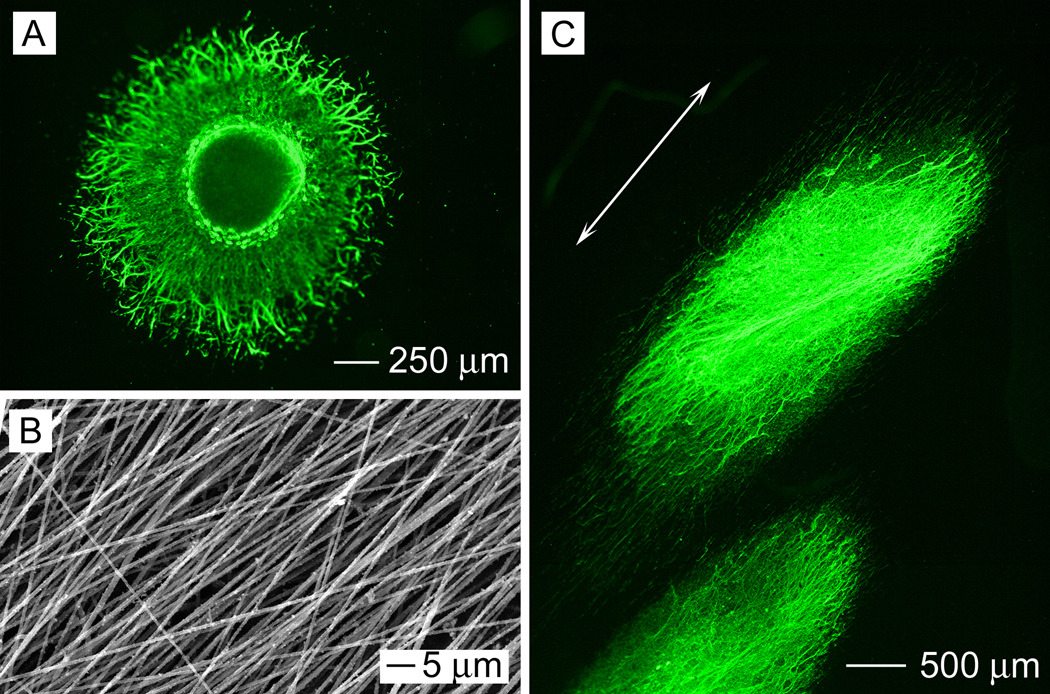
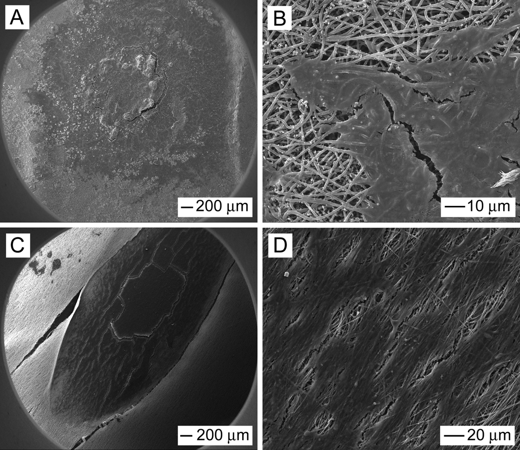
Figure 4A shows a typical fluorescence micrograph of the neurite field extending from a dorsal root ganglion seeded on a scaffold of random PCL-PPy core-sheath nanofibers. In this case, the neurites grew radially outward from the main body of the dorsal root ganglion without preference to any specific direction, displaying a rounded, spokes-of-a-wheel appearance. Figure 4B shows a fluorescence micrograph of the neurite field extending from a dorsal root ganglion seeded on a scaffold of uniaxially aligned PCL-PPy core-sheath nanofibers. It can be clearly observed that the neurites preferred to grow along the underlying nanofibers, with their orientation parallel to the long axes of the nanofibers. Figure 5 shows SEM images of neurite fields of DRG seeded on random and aligned PCL-PPy nanofiber scaffolds. We observed the similar results as fluorescence microscopy images. These results agreed well with previous studies where DRG were cultured on electrospun nanofibers[3–5], suggesting the PPy coating layer did no alter the topography significantly. Previous studies have established that the directional extension of neurites is a result of the traction force exerted by filopodia and this force is determined by the extent to which these protein filaments can accumulate, assemble, and orient in the direction of a cell protrusion.[29,30] We speculate that this mechanism is also responsible for the alignment of neurites observed in the present work. When DRG were cultured on the surface of randomly oriented nanofibers with suitable fiber density, the strength of the traction force exerted by a filopodium was uniform in all directions similar to the responses on isotropic films. The neurites emerged from the DRG main body in all directions and exhibited a radial distribution surrounding the main body of the DRG. In contrast, when cultured on the surface of aligned nanofibers, the strength of the traction force exerted by filopodia was no longer uniform due to the anisotropy exerted by the aligned nanofibers. Filopodia projecting from neurites on aligned nanofibers were limited in their directions of extension and the growth cone of neurites extending from the DGR might become extremely simplified with a single filopodium or narrow lamellipodial structures tapering to a filopodium.[31] The neurites therefore preferred to extend along the long axes of the nanofibers rather than stepping across fibers.
Figure 4.
(A) Fluorescence micrograph showing the DRG neurite field on random PCL-PPy core-sheath nanofibers. (B) Aligned PCL-PPy core-sheath nanofibers. (C) Fluorescence micrograph showing the DRG neurite field on aligned PCL-PPy core-sheath nanofibers. (The arrow indicates the alignment direction for the underlying nanofibers).
Figure 5.
SEM images of typical neurite fields of DRG seeded on random (A, B) and aligned (C, D) core-sheath PCL-PPy nanofiber scaffolds.
Additionally, fluorescent micrographs demonstrate that the maximum lengths of neurites projecting across aligned core-sheath fibers were much longer than those of neurites projecting across random fiber materials. This finding indicates that fiber alignment could not only guide neurite growth along a specific axis but also enhance the rate of neurite extension. Similar results were also found when using microfilaments as substrates for DRG culture.[32,33] However, one prior study reported that patterned microscale features of PPy did not lead to any significant increase in axon length from hippocampal cells compared to samples cultured on PPy films.[10] This different result could be attributed to the insufficient spatial resolution of the PPy microstructures for the response of neuron cells.
We also investigated the synergetic effect of electrical stimulation and topographic cues on neurite outgrowth using both random and aligned conductive core-sheath nanofibers. The impedance of conductive nanofibers at 1 kHz is crucial to the material’s ability to stimulate neuronal activity as this frequency corresponds to the characteristic frequency of neuronal-action potentials. [34] In general, the impedance should be as low as possible. The impedance of PCL nanofibers at 1 kHz decreased by three orders of magnitude (from 4×10⁷ Ω to 4×10⁴ Ω) upon coating with PPy sheaths. The aligned nanofiber mat with a low fiber density tended to fold in the medium and thus difficult to manipulate. For this reason, samples containing both random and aligned regions were employed in the present work to examine the effect of electrical stimulation on DRG seeded on the aligned nanofibers. Through this approach, the fiber mat with suitable fiber density can be easily manipulated and connected to the electrodes for electrical stimulation. In a typical experiment, a mat of random or random-aligned-random nanofibers was fixed to a custom-built culture plate with silver electrodes connecting to the two ends. A constant voltage of 10 V was then applied across the mat for 4 h per day during cell culture. The effective DC current applied to the sample was estimated to be 250 µA, a value within the range (0.6 µA to 400 µA) previously used by other groups in electrical stimulation studies.[35,36]
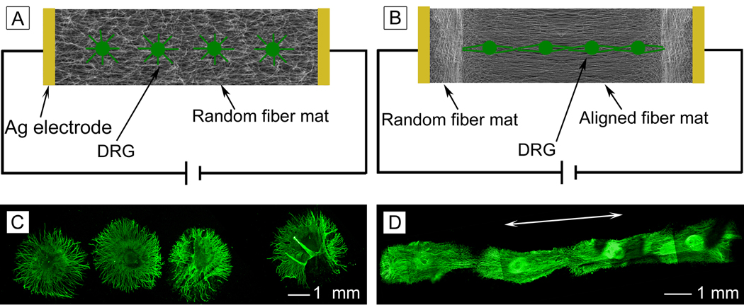
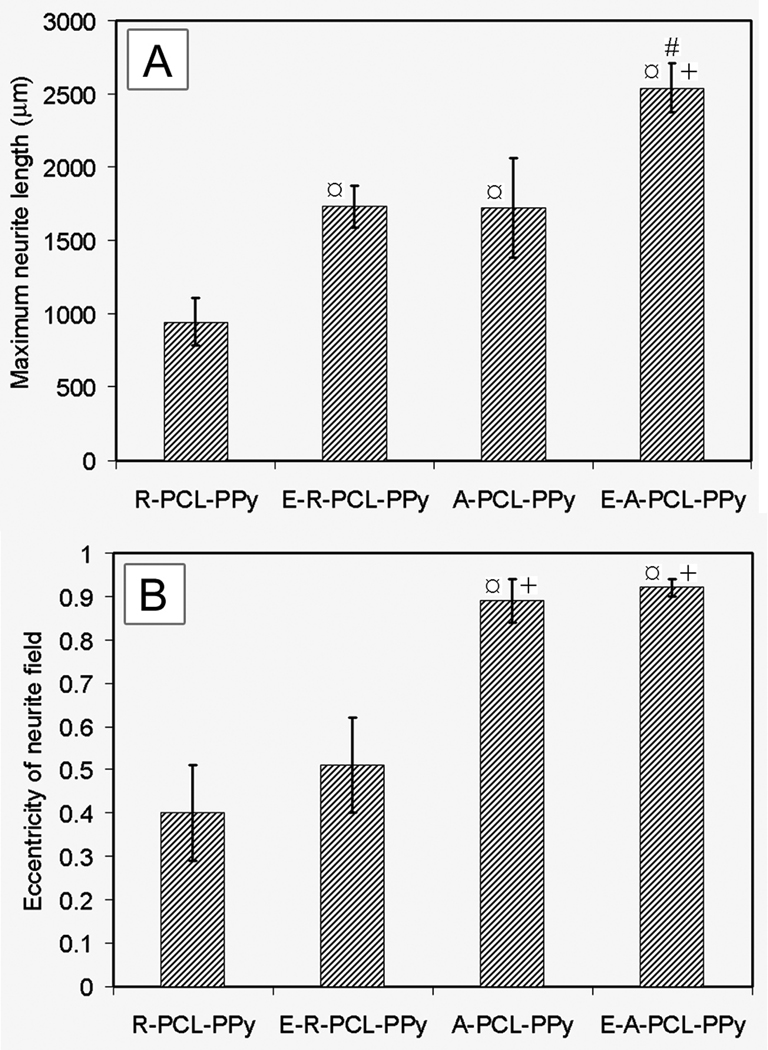
Figure 6, A and B, schematically illustrates how electrical stimulation was applied during the culture study. Figure 6, C and D, shows fluorescence micrographs of neurite fields projecting from DRG cultured on random and aligned nanofibers, respectively. To quantify the effect of fiber alignment and electrical stimulation on neurite length and eccentricity of neurite field, micrograph of cultured neurite fields were processed using custom MATLAB software as described in our previous study.[6] Although some DRG explants may grow together especially when DRG on aligned samples via electrical stimulation (Fig. 6D), the program was able to distinguish the edge of each DRG. The results of this analysis are shown in Figure 7, demonstrating that maximum neurite length was significantly enhanced on aligned fiber samples (1723 ± 339 µm) as compared to random fiber samples (946 ± 164 µm), which is likely due to the fact that neurites grow faster in their preferred orientation.[37] Accordingly, the eccentricity of the neurite fields was also greater for DRG cultured on aligned nanofibers (0.91 ± 0.02) than on random nanofibers (0.52 ± 0.09). A significant increase in maximum length of neurite was observed between DRG cultured on random nanofibers with and without electrical stimulation: 1733 ± 141 µm versus 946 ± 164 µm. As expected, no significant difference was observed in eccentricity for the neurite fields on random nanofibers without and with electrical stimulation: 0.49 ± 0.05 and 0.52 ± 0.02, respectively. Examination of neurites projecting from DRG cultured on aligned nanofibers showed a similar tendency. Specifically, the maximum length of neurite projecting along the aligned nanofibers was 2542 ± 171 µm and 1723 ± 339 µm, respectively, in the presence and absence of electrical stimulation. We observed more effect of electrical stimulation on random nanofibers compared to uniaxially aligned ones. This is perhaps because neurites could have some limit to grow to a certain length for a fixed period of time. Our present work and one prior study demonstrated that aligned nanofibers can promote neurite extension as compared to random nanofibers.[3] Electrical stimulation through aligned nanofibers could only further promote neurite extension to some extent. In contrast, electrical stimulation through random nanofibers could enhance neurite extension more as the length of neurites on random nanofibers is shorter than that on aligned nanofibers when no electrical stimulation was applied. Again, the eccentricity of neurite field on aligned nanofibers was essentially the same in the presence (0.92 ± 0.02) or absence (0.91 ± 0.02) of electrical stimulation. Overall, the electrical stimulation seems to have little influence on the eccentricity of neurite fields projecting on either random or aligned fiber mats.
Figure 6.
(A, B) Schematic illustration of DRG neurite outgrowth in the presence of electrical stimulation on random and uniaxially aligned PCL-PPy core-sheath nanofibers, respectively. (C) Typical DRG neurite field on random PCL-PPy nanofibers where the sample was cultured under electrical stimulation 4 h per day for 6 days. (D) Typical DRG neurite field on aligned PCL-PPy nanofibers after culturing under electrical stimulation 4 h per day for 6 days. The arrow marks the alignment direction for the underlying nanofibers. Note that the panel in (C) or (D) was assembled from a set of fluorescence micrographs taken from the same sample.
Figure 7.
(A) Maximum neurite length. (B) Eccentricity of neurite field. ¤ indicates p< 0.05 for samples compared with R-PCL-PPy sample. + indicates p< 0.05 for samples compared with E-R-PCL-PPy sample. # indicates p< 0.05 for samples compared with A-PCL-PPy sample. Abbreviations: R-PCL-PPy: randomly-oriented PCL-PPy core-sheath nanofibers; E-R-PCL-PPy: electrically stimulated R-PCL-PPy; A-PCL-PPy: aligned PCL-PPy core-sheath nanofibers; E-APCL-PPy: electrically stimulated A-PCL-PPy.
These findings indicate that the electrical stimulation enhanced the rate of neurite extension on both random and aligned nanofibers even though it did not change the way in which neurites responded to the topographic cues. The molecular basis underlying the electrical stimulation of neurite outgrowth is yet to be fully understood. The increase in the rate of neurite extension via electrical stimulation may be caused by an increased adsorption of ECM adhesive glycoproteins on electrically charged PPy, resulting in better neuronal attachment and thus enhanced neurite outgrowth.[38] The other possible factors could include electrophoretic redistribution of molecular compounds involved in the formation of growth cone, favorable protein conformational changes, polarization of nerves, enhanced protein synthesis, and field-induced ionic and molecular gradients in the culture medium.[7] Electrical stimulation might also promote the migration of Schwann cells on the fiber scaffolds and hence enhance the extension of neurites. This aspect will be investigated in our future studies. It is clear that a combination of conductive core-sheath nanofibers and electrical stimulation will offer many advantages over other types of stimulations (e.g., exogenous electromagnetic fields and static surface charges of electret materials) and allow for precise regulation, spatial control, and guidance of neurite outgrowth.[7]
It is worth pointing out that neurotrophic factors, ECM proteins, and other types of functional molecules can also be incorporated into or on the surface of the PPy sheath as a means of further enhancing neurite outgrowth on scaffolds based on nanofibers.[39–44] Cells (e.g., neural stem cells, embryonic stem cells) could be seeded on the core-sheath nanofibers as well to form artificial nervous tissue grafts.[6] These approaches may allow for the design of advanced nerve conduits capable of simultaneously presenting electrical stimulation, topographic cues, and biochemical signals for nerve injury repair. In addition, conductive core-sheath nanofibers may also be implemented as new types of neural probes or biosensors due to their large surface areas.
3. Conclusions
In summary, we have demonstrated a simple and versatile approach to the fabrication of conductive core-sheath nanofibers by combining electrospinning with aqueous polymerization. We have further investigated their potential use as scaffolds for neural tissue engineering. When DRG were cultured on these core-sheath nanofibers, the neurite extension could be uniaxially aligned and enhanced by 1.82-fold on uniaxially aligned nanofibers as compared with scaffolds consisting of random fibers. Furthermore, the maximum length of neurites could be increased by 1.83-fold and 1.47-fold on the random and aligned nanofibers, respectively, when an electrical stimulation was applied. All these results could contribute to a better design of a nerve conduit with incorporation of the synergistic effect of electrical, topographic and feasible biochemical cues for nerve injury repair.
4. Experimental
Electrospinning of Nanofibers
In a typical procedure for electrospinning PCL (Mw=65 kDa) nanofibers, we used a solution of 10% (w/v) PCL in DCM (Cole-Parmer) containing 2 mM ionic surfactant cetyltrimethylammonium bromide (CTAB) (Sigma-Aldrich) or a solution of 20% (w/v) PCL in a mixture of DCM and DMF (Cole-Parmer). The fibers were spun at 10–17 kV with a feeding rate ranging from 0.5 mL/h to 1.5 mL/h, together with a 23 gauge needle. A piece of aluminum foil or a stainless steel frame (with an open void of 2 cm × 5 cm) was used as the collector to obtain random and aligned nanofibers, respectively. In addition, samples containing both random and aligned fibers next to each other were obtained by using two metal frames separated by an air gap. Fibers were deposited in the random and aligned form on the metal part and across the air gap, respectively. For PLA (Mw=700 kDa) nanofibers, we used a 1.0% (w/v) solution in DCM, which also contained 2 mM ionic surfactant CTAB.
Formation of Core-Sheath Nanofibers
The PPy was coated on electrospun PCL and PLA nanofibers by in situ polymerization with Fe3+ or APS as an oxidant, together with Cl− or PTSA as a dopant, respectively. A piece of nanofiber mat was immersed in a 0.04 M aqueous solution of pyrrole (10 mL). The polymerization of pyrrole and thus deposition of PPy coatings on the PCL or PLA nanofibers at room temperature were initiated with the addition of 10 mL aqueous solution of FeCl3 (0.084 M). The mixture was shaken vigorously for 1 h. The PCL and PLA nanofibers changed appearance from white to dark due to the coating of black PPy during polymerization. The fiber mat with PPy coating was then washed with 18 mΩcm water several times to remove the loosely attached PPy particles and was finally dried in a vacuum prior to use. Similar procedures were applied to the coating of PCL and PLA nanofibers with PPy that used APS as an oxidant and PTSA as a dopant.
Characterization of the Core-Sheath Nanofibers
SEM images and EDX were obtained by imaging the sample of fibers supported on a Si substrate with an FEI Sirion microscope at an accelerating voltage of 5 kV. PCL and PLA nanofibers were sputtered with Au/Pd for 40 s before imaging. TEM images of the solvent-extracted samples were obtained from samples supported on carbon-coated copper grids using a Philips CM100 TEM microscope with a Gatan 689 digital camera. Impedance of fabricated nanofiber scaffolds was measured by passing a 1 kHz sine wave of controlled amplitude through fabricated samples using an impedance check module (FHC Inc., Bowdoin, ME).
DRG Culture
Chick embryos, embryonic day 8 (E8, stage HH35-36), were removed from the eggs and decapitated. DRG were dissected from the thoracic region and collected in HBSS prior to plating. The DRG were then plated onto the nanofiber scaffolds and incubated in modified NB media (Neurobasal media, 1% ABAM; 1% N-2 Supplement, GIBCO/Life Technologies). Thin films consisting of PCL-PPy core-shell nanofibers were cut and fixed in cell culture plates as controls. For electrical stimulation experiment, the random and random-aligned-random fiber scaffolds were fixed to a custom-design culture dish with a diameter of 30 mm and a constant voltage (10 V) was applied across the scaffold for 4 h per day during the period of culture. Three substrates and 12 explants were used for each experiment. In our study, we applied electrical stimulation through two external electrodes placed outside the culture medium. Therefore, there should be no ionic current between the two electrodes.
DRG Immunostaining
After 6 days of incubation, DRG were immunostained with anti-NF200 (1:500; Sigma-Aldrich, St. Louis, MO), a neuronal marker. Briefly, DRG were fixed in 3.7% formaldehyde for 45 min and permeabilized by 0.1% triton x-100 for 30 min. The sample was then blocked in PBS containing 5% normal goat serum (NGS) (Invitrogen, Carlsbad, CA) for 1 h. The anti-NF200 diluted with PBS containing 2% NGS was then applied to the cells overnight at 4 °C. Following a triple wash with PBS, DRG were incubated with the secondary antibody, AlexaFluro 488 goat anti-mouse IgG (1:200; Invitrogen). Fluorescence images were taken using a QICAM Fast Cooled Mono 12-bit camera (Q Imaging) attached to an Olympus microscope with Capture 2.90.1 (Olympus). The images were processed with a program written with MATLAB to calculate the eccentricity, and the maximum length of neurites.[6] Briefly, a custom-designed computer program, created using MATLAB (MathWorks Inc., Novi, MI, USA), was utilized to analyze fluorescent micrographs of DRG neurite field on either random or aligned nanofiber sample. Neurite field eccentricity (a measure of directed neurite growth along a given axis) and maximum length of neurite extension (a measure of the rate of neurite growth) were calculated for each sample. Calculations were accomplished by separately fitting the leading edge of the neurite field and the perimeter of the DRG cell mass to standard elliptical equation (1) at point (h, k) of the form:
| (1) |
where a and b are the ellipse's semimajor and semiminor axes.
Eccentricity of the neurite field was then calculated from equation (2):
| (2) |
Where the values of “a” and “b” were obtained from the elliptical equation fit to the leading edge of the neurite field. Maximum length of neurite extension was then calculated as the greatest distance between the elliptical curve marking leading edge of the neurite field and the elliptical curve marking the boarder of the DRG cell mass along a line oriented radially from the center of the DRG cell mass.
Mean values and standard deviation were reported. Statistical analysis of the maximum length of neurites, and eccentricity of neurite field was performed using the Scheffe’s F post hoc test by analysis of variance at a 95% confidence level.
SEM characterization of DRG
The DRG were fixed in 3.7% formaldehyde for 30 min. Subsequently, it was dehydrated in ethanol with a series of concentrations (30%, 50%, 70%, 90%, 95%, and 100%) and dried in vacuum. Finally, the sample was coated with platinum using a sputter prior to imaging by SEM. The accelerating voltage was 15 kV for imaging.
Supplementary Material
Footnotes
This work was supported in part by an NIH Director's Pioneer Award (5DP1OD000798) and start-up funds from Washington University in St. Louis. X.L. is a visiting Ph.D. student from the School of Materials Science and Engineering, Tianjin University, Tianjin, China and partially supported by the National Council of Scholarship.
References
- 1.Hudson TW, Evans GRD, Schmidt CE. Clin. Plast. Surg. 1999;26:617. [PubMed] [Google Scholar]
- 2.Schmidt CE, Leach JB. Ann. Rev. Biomed. Eng. 2003;5:293. doi: 10.1146/annurev.bioeng.5.011303.120731. [DOI] [PubMed] [Google Scholar]
- 3.Corey JM, Lin DY, Mycek KB, Chen Q, Samuel S, Feldman EL, Martin DC. J. Biomed. Mater. Res. 2007;83A:636. doi: 10.1002/jbm.a.31285. [DOI] [PubMed] [Google Scholar]
- 4.Schnell E, Klinkhammer K, Balzer S, Brook G, Klee D, Dalton P, Mey J. Biomaterials. 2007;28:3012. doi: 10.1016/j.biomaterials.2007.03.009. [DOI] [PubMed] [Google Scholar]
- 5.Chow WN, Simpson DG, Bigbee JW, Colello RJ. Neuron Glia Biol. 2007;3:119. doi: 10.1017/S1740925X07000580. [DOI] [PMC free article] [PubMed] [Google Scholar]
- 6.Xie J, Willerth SM, Li X, Macewan MR, Rader A, Sakiyama-Elbert SE, Xia Y. Biomaterials. 2009;30:354. doi: 10.1016/j.biomaterials.2008.09.046. [DOI] [PMC free article] [PubMed] [Google Scholar]
- 7.Schmidt CE, Shastri VR, Vacanti JP, Langer R. PNAS. 1997;94:8948. doi: 10.1073/pnas.94.17.8948. [DOI] [PMC free article] [PubMed] [Google Scholar]
- 8.Patel S, Gao H, Hsiao BS, Poo M, Li S. Nano. Lett. 2007;7:2122. doi: 10.1021/nl071182z. [DOI] [PubMed] [Google Scholar]
- 9.Chew SY, Mi R, Hoke A, Leong KW. Adv. Funct. Mater. 2007;17:1288. doi: 10.1002/adfm.200600441. [DOI] [PMC free article] [PubMed] [Google Scholar]
- 10.Gomez N, Lee JY, Nickels JD, Schmidt CE. Adv. Funct. Mater. 2007;17:1645. doi: 10.1002/adfm.200600669. [DOI] [PMC free article] [PubMed] [Google Scholar]
- 11.Dong H, Jones WE., Jr Langmuir. 2006;22:11384. doi: 10.1021/la061399t. [DOI] [PubMed] [Google Scholar]
- 12.Valero-Cabre A, Tsironis K, Skouras E, Perego G, Navarro X, Neiss WF. J. Neurosci. Res. 2001;63:214. doi: 10.1002/1097-4547(20010115)63:2<214::AID-JNR1014>3.0.CO;2-D. [DOI] [PubMed] [Google Scholar]
- 13.Evans GR, Brandt K, Niederbichler AD, Chauvin P, Herrman S, Bogle M, Otta L, Wang B, Patrick CW., Jr J. Biomater. Sci. Polym. Ed. 2000;11:869. doi: 10.1163/156856200744066. [DOI] [PubMed] [Google Scholar]
- 14.Evans GR, Brandt K, Katz S, Chauvin P, Otto L, Bogle M, Wang B, Meszlenvi RK, Lu L, Mikos AG, Patrick CW., Jr Biomaterials. 2002;23:841. doi: 10.1016/s0142-9612(01)00190-9. [DOI] [PubMed] [Google Scholar]
- 15.George PM, Lyckman AW, LaVan DA, Hedge A, Leung Y, Avasare R, Testa C, Alexander PM, Langer R, Sur M. Biomaterials. 2005;26:3511. doi: 10.1016/j.biomaterials.2004.09.037. [DOI] [PubMed] [Google Scholar]
- 16.Wadhwa R, Lagenaur CF, Cui XT. J. Controlled Rel. 2006;110:531. doi: 10.1016/j.jconrel.2005.10.027. [DOI] [PubMed] [Google Scholar]
- 17.Wang X, Gu X, Yuan C, Chen S, Zhang P, Zhang T, Yao J, Chen F, Chen G. J. Biomed. Mater. Res. 2004;68A:411. doi: 10.1002/jbm.a.20065. [DOI] [PubMed] [Google Scholar]
- 18.Konturri K, Pentti P, Sundholm G. J. Electroanal. Chem. 1998;453:231. [Google Scholar]
- 19.Shastri VR, Schmidt CE, Kim TH, Vacanti JP, Langer R. Mater. Res. Soc. Sym. Proc. 1996;414:113. [Google Scholar]
- 20.Rivers TJ, Hudson TW, Schmidt CE. Adv. Funct. Mater. 2002;12:33. [Google Scholar]
- 21.Bognitzki M, Hou H, Ishaque M, Frese T, Hellwig M, Schwarte C, Schaper A, Wendorff JH, Greiner A. Adv. Mater. 2000;12:637. [Google Scholar]
- 22.Zeng J, Aigner A, Czubayko F, Kissel T, Wendorff JH, Greiner A. Biomacromolecules. 2005;6:1484. doi: 10.1021/bm0492576. [DOI] [PubMed] [Google Scholar]
- 23.Abidian MR, Kim DH, Martin DC. Adv. Mater. 2006;18:405. doi: 10.1002/adma.200501726. [DOI] [PMC free article] [PubMed] [Google Scholar]
- 24.Wang X, Kim Y, Drew C, Ku B, Kumar J, Samuelson LA. Nano. Lett. 2004;4:331. [Google Scholar]
- 25.Peng Q, Sun XY, Spagnola JC, Hyde GK, Spontak RJ, Parsons GN. Nano. Lett. 2007;7:719. doi: 10.1021/nl062948i. [DOI] [PubMed] [Google Scholar]
- 26.McCann JT, Lim B, Rainer O, Rycenga M, Marquez M, Xia Y. Nano. Lett. 2007;7:2470. doi: 10.1021/nl071234k. [DOI] [PubMed] [Google Scholar]
- 27.Li D, Xia Y. Adv. Mater. 2004;16:361. [Google Scholar]
- 28.Li D, Wang Y, Xia Y. Nano Lett. 2003;3:1167. [Google Scholar]
- 29.Mahoney MJ, Chen RR, Tan J, Saltzman WM. Biomaterials. 2005;26:771. doi: 10.1016/j.biomaterials.2004.03.015. [DOI] [PubMed] [Google Scholar]
- 30.Tan J, Saltzman WM. Biomaterials. 2002;23:3215. doi: 10.1016/s0142-9612(02)00074-1. [DOI] [PubMed] [Google Scholar]
- 31.Clark P, Britland S, Connolly P. J. Cell Sci. 1993;105:203. doi: 10.1242/jcs.105.1.203. [DOI] [PubMed] [Google Scholar]
- 32.Rangappa N, Romero A, Nelson KD, Eberhart RC, Smith GM. J. Biomed. Mater. Res. 2000;51:625. doi: 10.1002/1097-4636(20000915)51:4<625::aid-jbm10>3.0.co;2-u. [DOI] [PubMed] [Google Scholar]
- 33.Smeal RM, Rabbitt R, Biran R, Tresco PA. Ann. Biomed. Eng. 2005;33:376. doi: 10.1007/s10439-005-1740-z. [DOI] [PubMed] [Google Scholar]
- 34.Kandel ER, Schwarts JH, Jessel TM. Principles of Neural Science. Norwalk, CT: Appleton & Lange; 1991. [Google Scholar]
- 35.Kow LM, Pfaff DW. Brain Res. 1985;347:1. doi: 10.1016/0006-8993(85)90883-2. [DOI] [PubMed] [Google Scholar]
- 36.Kerns JM, Fakhouri AJ, Weinrib HP, Freeman JA. Neurosci. 1991;40:93. doi: 10.1016/0306-4522(91)90177-p. [DOI] [PubMed] [Google Scholar]
- 37.Rajnicek AM, Britland S, McCaig CD. J. Cell Sci. 1997;110:2905. doi: 10.1242/jcs.110.23.2905. [DOI] [PubMed] [Google Scholar]
- 38.Kotwal A, Schmidt CE. Biomaterials. 2001;22:1055. doi: 10.1016/s0142-9612(00)00344-6. [DOI] [PubMed] [Google Scholar]
- 39.Kim DH, Richardon-Burns SM, Hendricks JL, Sequera S, Martin DC. Adv. Funct. Mater. 2007;17:79. [Google Scholar]
- 40.George PM, LaVan DA, Burdick JA, Chen CY, Liang E, Langer R. Adv. Mater. 2006;18:577. [Google Scholar]
- 41.Song HK, Toste B, Ahmann K, Hoffman-Kim D, Palemore GTR. Biomaterials. 2006;27:473. doi: 10.1016/j.biomaterials.2005.06.030. [DOI] [PubMed] [Google Scholar]
- 42.Sanghvi AB, Miller KP, Belcher AM, Schmidt CE. Nature Mater. 2005;4:496. doi: 10.1038/nmat1397. [DOI] [PubMed] [Google Scholar]
- 43.Richardson RT, Thompson B, Moulton S, Newbold C, Lum MG, Cameron A, Wallace G, Kapsa R, Clark G, O’Leary S. Biomaterials. 2007;28:513. doi: 10.1016/j.biomaterials.2006.09.008. [DOI] [PubMed] [Google Scholar]
- 44.Gomez N, Schmidt CE. J. Biomed. Mater. Res. A. 2007;81:135. doi: 10.1002/jbm.a.31047. [DOI] [PMC free article] [PubMed] [Google Scholar]
Associated Data
This section collects any data citations, data availability statements, or supplementary materials included in this article.


