Abstract
Patterned carbon nanotubes arrays (PCNTA) with reduced density and length were developed with polystyrene sphere masked catalyst dots followed by plasma enhanced chemical vapor deposition method. The nanotubes were then uniformly coated with electropolymerized polypyrrole (PPy). The coating thickness was conformally adjustable. Gold nanoparticles (AuNP) together with glucose oxidase (Gox) were doped into the PPy film on the nanotubes to develop a high performance PCNTA glucose sensor. The sensitivity of the sensor was improved by the co-existence of Gox and AuNP on the carbon nanotube. Moreover, in contrast to previous reported PCNTA glucose sensors, the design herein utilized the entire surface of nanotubes as active sensing areas in order to maximize the Faradic currents. This research outlines a practical avenue to fabricate high performance PCNTA sensor chips with multiple molecules and functional nano-architectures.
1. Introduction
The unique electrical, chemical, and mechanical properties of carbon nanotubes (CNTs) can be utilized to develop advanced nano/micro devices [1]. A critical issue for the applications of CNTs concerns the modification of the nanotube surface with chemical groups or functional materials to obtain advanced electrical and chemical properties [2]. CNTs decorated with enzymes and metal nanoparticles represent a novel kind of functional material to produce a new generation of mediator-free electrochemical biosensor [3]. Aligned carbon nanotubes (ACNTs) grown on a substrate can form an array structure exhibiting particular advantages to inspire research for applications in high definition displays [4], optic electronics [5], and sensors [6,7] etc. ACNT arrays with enzymes and metal nanoparticles co-functionalization may exert extraordinary biosensing performance. Unfortunately, many approaches used to modify the CNT surface to attach enzymes and metal particles involve detrimental physical and chemical treatments that can destroy the ACNT array structures.
ACNTs can be synthesized by chemical vapor deposition (CVD) [8] and plasma enhanced chemical vapor deposition (PECVD) [9]. The latter method yields lower site density ACNT arrays with enough spacing between CNTs to avoid physical contact between each other [10]. Such a character reserves a superior advantage to develop the array of CNTs that are individually addressable, thereafter being used in high throughput lab-on-chip sensor chip.
PECVD-based CNT grown from thin film catalyst can make the ACNTs at a density of 109 to 1010/cm2 [9]. With electrochemical deposition of discrete catalyst dots on substrate, the array density was reduced to 105/cm2 that was favored by electrochemical sensor development [11]. However, both methods yield randomly grown CNTs preventing any determination of the number of CNTs on the chip. Periodically patterned CNT array (PCNTA) have been grown from polystyrene microsphere monolayer masked catalyst dot arrays [12]. They have low and strictly adjustable site density, coming with accurately defined CNT numbers and localization in a designated area.
Regularly biosensors work in liquid environments. The as-grown ACNTs can not withstand the surface tension of such environments and bend and break. [13]. One countermeasure for the surface tension was to use epoxy or other dielectric materials to embed the array and get the CNTs permanently supported [7]. The only active detection surface is the CNT tip which is exposed after an abrasive polishing of the top side of the sensor. The insurmountable disadvantage was that the CNTs lost their side walls as the active detection surface.
In this paper, we used polystyrene spheres of 1.5 μm in diameter to produce CNT arrays at the lowest achievable density, i.e. 2 × 10⁷/cm2. For the first time, we co-immobilized gold nanoparticle (AuNP) and glucose oxidase on the ACNT surface by doping electropolymerized polypyrrole (PPy) to explore the improvement of sensor performance. With PPy as a supporting layer coated outside each CNT, the PCNTA can keep its original morphology after experiencing aqueous buffer such as phosphate buffered saline (PBS). Thanks to the identical site density of CNTs on chips, the sensor performance is more identical and comparable. Among different sensor preps, the one composed of Gox and AuNP exhibited maximum glucose sensitivity. Enzymatic kinetics analysis also indicated the boosted electron transfer from Gox in this sensor.
2. Experimental
2.1. Apparatus
Electrochemistry experiments were performed with a Gamry PC4/750 that was linked to a Pentium III computer system. Gamry Instruments Framework and Gamry Echem Analyst software were used for recording and analyzing data. For the measurement of the glucose sensor, the Ag/AgCl reference electrode, and platinum wire counter electrode were inserted into the Dr. Bob’s cell (Gamry Instruments, Warminster, PA). Scanning electron microscopy (SEM) was conducted with JEOL J6400. High resolution transmission electron microscopic (HRTEM) images were obtained with JEOL 2010F. Samples used for TEM measurement were scratched out from the surface of Si substrate with PACNT and then suspended in ethyl alcohol and cast (4 μL) on a carbon film coated Cu grid and air dried at room temperature.
2.2. Chemicals and Materials
All solutions were prepared from double-distilled water. Glucose and glucose oxidase (Gox) were obtained from Sigma (Saint Louis, MO). Phosphate buffered saline (PBS) was obtained from Fisher Scientific (Suwanee, GA). Pyrrole solution and AuNP were purchased from Aldrich.
2.3. Preparation of periodic carbon nanotube arrays
PCNTA were prepared according to the previous report [12]. Briefly, Ni was deposited on chromium coated 10×10 mm2 Si wafers through polystyrene microsphere monolayer by electron beam evaporation. Periodically patterned Ni was revealed after removal of the spheres by sonication. Then the Ni was annealed and plasma etched at 550°C for 2 min. CNTs were grown by supplying NH3 at 160 sccm and C2H2 at 60 sccm in the presence of plasma and temperature for 5 min. The CNTs length was 1–2 μm determined by the growth time. The CNTs diameter was 120 nm on average and the inter-spacings between adjacent CNTs in the hexagonal pattern were 1.61, 1.27 and 0.75 μm. (Fig. 1A).
Fig. 1.
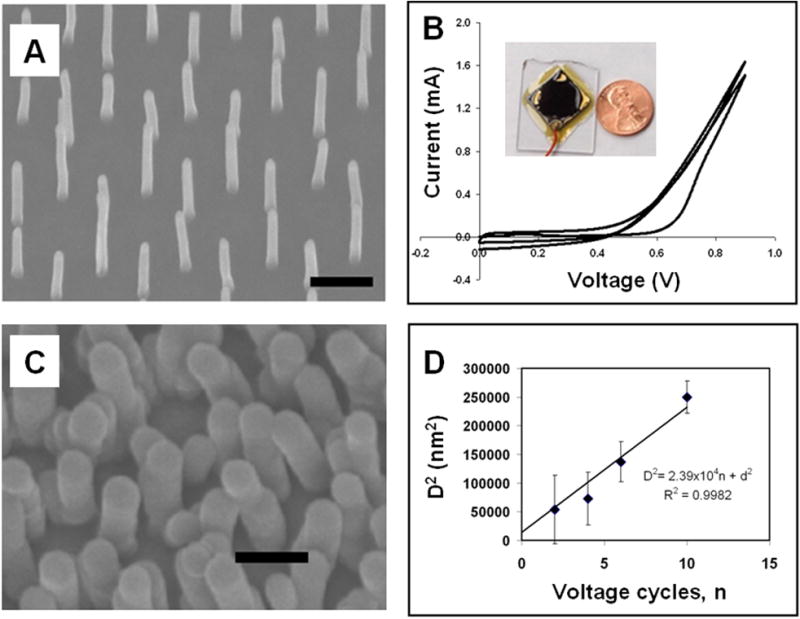
Patterned carbon nanotube arrays (PCNTA) and their electropolymerized polypyrrole coating. The average as-grown CNTs (A) diameter was 120 nm. Electropolymerization was used to deposit polypyrrole, on the CNTs (B). To conduct electropolymerization, a PCNTA electrode was made by back-attaching to a glass and edge-sealing with epoxy (inset of B). Larger structures (C) were observed under scanning electron microscopy after 10 voltage cycles. The relationship of CNT-PPy diameters vs. the deposition voltage cycle numbers is shown in D. The scale bar shown in A and C is 1 μm.
2.4. Biosensors fabrication and electrochemical recording
Electropolymerized polypyrrole (PPy) was used to coat the CNT surface in the array with reported procedures [14]. The PCNTA were included in a standard three-electrode recording system as the working electrode. A platinum wire served as counter electrode and AgCl coated Ag foil was used as reference electrode. The buffer contained 0.5 M pyrrole and 0.1 M NaCl. Cyclic voltammetry (CV) was performed with the voltage scanned from 0 to 0.9 V at 100 mV/s, and the thickness of PPy coating was determined by the number of running cycles. Gox and AuNP suspension (diameter = 3 nm, U.V. Absorption Unit520 = 0.8) were supplemented to the buffer by various dilution from the stocks to co-immobilize Gox and AuNP. For Gox, the dilution (v/v) is from 1:10 to 1:200. For AuNP, the dilution (v/v) was 1:10.
To determine the sensitivity, glucose sensors were included as working electrodes in the three-electrode system. The electrodes were immersed in 5 mL of PBS (pH 7.0) supplemented with designated amounts of glucose in the Dr. Bob’s cell. For voltammetry recording, the scanning rate and scanning voltage range were varied depending on the experimental design. The electrodes and all solutions were prepared freshly before each experiment.
3. Results and Discussions
Following previously reported electropolymerization procedures [6,14], PPy was uniformly coated on the PCNTA in a very controllable manner as shown in Fig. 1A and C. The reaction was monitored by the cyclic voltammetric I-V curves (Fig. 1B). Assuming that all PPy molecules have the same volume (α) in the coating film, then the total charge generated from electropolymerization of pyrrole (Q), the volume of PPy in the coating (ΔV) and the amount of voltage cycles (n) can be correlated as:
| (1) |
where k is a constant proportional to the charge generated in each voltage cycle.
| (2) |
where d and D are diameters before and after PPy deposition, and h is the height of the CNT, we have:
| (3) |
with .
Such relationship was observed in our experiments and shown in Fig. 1D. On average, the diameter of as grown CNT is 120 nm. So we set the intercept at 14400 for the linear fitting. This result indicates that the PPy coating on PCNTA is well adjustable by the number of voltage cycles. For the sake of the relatively short length and low density of PCNTA, PPy was deposited uniformly throughout the CNTs from top to bottom (Fig. 1) with no indication of the pyrrole concentration gradient along the depth due to the reactants consumption [6]. The PPy coating can also provide an extra support to the CNTs instead of the epoxy, therefore making the PCNTA stable in a liquid with high surface tension. Since PPy is a conductive polymer, all the coated surfaces are available for electrochemical reaction with redox species and generation of faradic current. Thus the side walls of PPy coated CNTs can be utilized for detection.
As reported before, enzyme molecules such as Gox with negative charges can be doped into the positively charged PPy molecular structures to yield glucose sensors with a Gox-PPy coating on CNTs [6,15]. In the presence of oxygen, Gox can enzymatically convert glucose to hydrogen peroxide and gluconate. Faradic current can be generated in response to further electrochemical oxidization of hydrogen peroxide [16]. Additionally, the conductive PPy offers molecular level contact with Gox and may facilitate the electron transfer. It may in turn enhance the response to glucose of the PPy modified sensors. In our experiments, we observed good response to glucose with the sensors fabricated by electropolymerization with voltage ramping between 0 to 0.9 V at 100 mV/s for 2 cycles. Further improvements could be achieved by changing the combination of components in the sensor, as well as the thickness and porosity of PPy coating.
Colloidal AuNPs are usually stabilized with citrate and thereby negatively charged. So the AuNP doped PPy coating on PCNTA was also achievable by electropolymerization. The coating film was characterized by transmission electron microscopy (Fig. 2). The AuNP-PPy coating had a rougher surface than the PPy-only coating. The particle structures were also found inside the coating. The gold element was detected in the marked coating area (Fig. 2B and C) by energy dispersive X-ray analyzers (EDX). According to this observation, it is plausible to use electropolymerized PPy to entrap both AuNPs and Gox molecules on PCNTA in order to pursue enhanced glucose sensitivity by co-immobilization of enzymes and metallic nanoparticles as shown in previous bulky CNT-based glucose sensors [17,18].
Fig. 2.
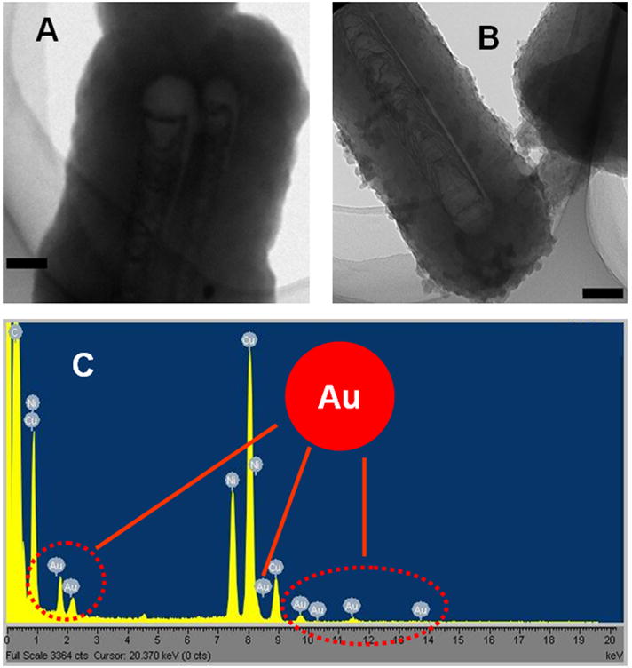
Transmission electron microscopy of PPy only (A) and AuNP-doped PPy (B) on ACNTs. The area marked with a red circle in B was subjected to EDX characterization (C). Red arrows in C indicate the peaks of Au. The scale bar shown in A and B is 100 nm.
Ferrocenecarboxylic acid (FCA) was supplemented to the recording buffer, i.e. PBS, with the final concentration of 1 mM. It will be oxidized to generate Faradic currents, which is proportional to the conductivity and electron transfer rate of the sensors. As shown in Fig. 3, changing the combination of AuNP and Gox can significantly alter the current. For example, the inclusion of AuNP in PPy boost the current from 190 nA to 9.2 μA. However, it is also demonstrated that the Gox co-deposition is correlated to the loss of the sensor electrochemical performance, since the Gox protein is not electrically conductive. Electrochemical impedance spectroscopy (EIS) data (to be presented in another publication) also indicate that over-doping PPy with Gox can reduce the overall conductivity in sensor surface, generate a voltage drop across the PPy coating, and result in loss of redox function of the sensor. With 0.005 wt% Gox, the sensor exhibits fairly high levels of electrochemical activity. Considering the trade-off between the electrode conductivity and enzymatic activity, 0.01 wt% of Gox was used in glucose sensors fabricated for the following study.
Fig. 3.
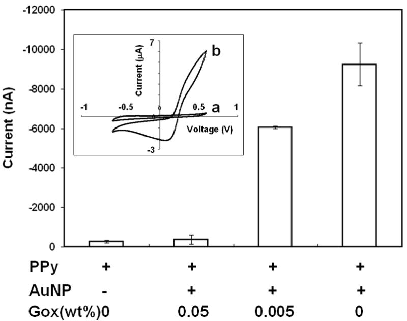
Electrode components and their effects on the electrochemical performance. There are four electrode conditions: PPy only, PPy plus AuNP and with 0.05, 0.005 and 0 wt% Gox. The Faradic current of 1 mM FCA was obtained at 600 mV. The inset shows the CV curves recorded in FCA supplemented PBS with PCNTA sensors containing PPy only (a) and PPy plus AuNP and 0.005 wt% Gox. Voltage scanned from −600 to 600 mV at 100 mV/s.
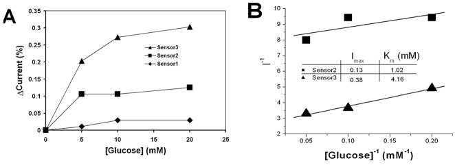
We had fabricated three kinds of glucose sensors: (1) Gox-PPy on Si substrate (sensor 1); (2) AuNP-Gox-PPy on Si substrate (sensor 2); and (3) AuNP-Gox-PPy on PCNTA grown on Si substrate (sensor 3). For the same amount of glucose, the current increased with the addition of AuNPs and Gox (Fig. 4A), resulting in higher sensitivity of sensor 2 over sensor 1. The molecular architecture formed inside the PPy film provided functional interactions among Gox, AuNPs, PPy, and CNTs, and allowed the facilitation of electron transfer from Gox to the electrode. Sensor 3 was apparently the most sensitive one among the three (i.e., at 20 mM glucose, the current amplitude of sensor 3 was approximately 2.4 times higher than that of sensor 2). The Gox mediated glucose oxidation can be simplified as:
| (4) |
Fig. 4.
The detection of glucose with the sensors. The component differences of the sensors are: Sensor 1 with Gox doped PPy on Si wafer; Sensor 2 with Gox and AuNP doped PPy on Si wafer; and Sensor 3 with Gox and AuNP doped PPy on PCNTA. Their glucose dosage-responses were compared by converting the glucose currents to the percentages of their base currents obtained in a glucose free buffer (A). The Lineweaver-Burk diagrams showed the differences of Michaelis-Menten kinetics between Sensors 2 and 3 (B).
Analyzed with Michaelis-Menten kinetics,
| (5) |
higher steady state Faradic currents and Michaelis-Menten constants were observed in sensor 3 than sensor 2 (Fig. 4B). The improvement might be partially ascribed to the additional surface area (5.22 mm2) of CNTs on the 3 × 3 mm2 Si substrate. The additional Gox immobilization on the extra CNT surface area on sensor 3 may increase the value of [Gox] in the equation of Imax:
| (6) |
where k2 is the turn over rate of the enzyme. In fact, the Imax of sensor 3 was nearly 200% higher than sensor 2 as shown in Fig. 4B, which outweighed the 58% that could be contributed by the larger surface areas. To thoroughly understand the enhancement in Imax and Km, we are planning more in-depth investigation in the future. Several special features of ACNT are proposed for such improvement. The catalyst particles embedded in CNT tips exhibited facilitation of hydrogen peroxide detection [6]. The huge curvatures of CNTs can enhance the electric field for Faradic current generation. The metallic CNTs of PCNTA [19] can also contribute to the electron transfer from the Gox molecules through AuNPs and CNTs down to the electrode [18], thereby improving the sensor’s response to glucose. Putting the results from our studies together with the supporting information from previous publications, the multifunctional structures are illustrated in Fig. 5 showing their assembly by the electroplymerized PPy film on CNTs. The most promising advantage is that the interactions among the components may contribute to the improvement of electron transfer from the enzymes to the electrodes. Recently, a multi-component composite was made of powder-like multi-walled CNTs, magnetic Fe3O4 nanoparticles, polyaniline and Gox to demonstrate glucose sensing [20]. In contrast, sensor structures fabricated with PCNTA herein exhibited particular benefits to the development of high performance lab-on-chip biosensing devices.
Fig. 5.
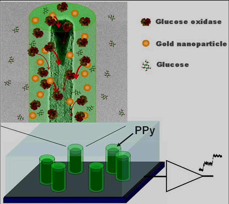
The structure and suggested mechanisms of PCNTA glucose sensor with multifunctional components. PPy coating serves as a conductive support to the PCNTA. Electron transfer is facilitated by the PPy itself and the co-doped AuNPs. Correspondingly, glucose oxidase molecules co-localized with AuNPs have high electron transfer rate and therefore larger output currents than that of the enzyme molecule alone.
4. Conclusions
We demonstrated a practical method to develop a PCNTA sensor device featuring polymer-mediated molecules and nanostructures co-modified on the CNT surface. The short PCNTA were prepared by PECVD on Si substrates using large sphere masks. A well adjustable electropolymerization strategy was used to uniformly coat the CNTs with multifunctional components such as PPy, AuNPs, and Gox. The fabricated PCNTA biosensor described herein was compatible to aqueous buffer, utilized the whole surface of CNTs for detection, and exhibited improved sensitivity due to the improvement of conductivity of PPy film and facilitation of electron transfer from Gox by AuNPs. Therefore, our research presents a practical and efficient method to fabricate PCNTA sensor with multi-functional components for improved biodetection applications.
Acknowledgments
Y. Y. thanks China Scholarship Council and National Science Foundation of China (No. 90510012); D.C. and T.C.C thank Naval Health Research Center/Environmental Health Effects Lab of Department of Navy (FA8601-07-P-0548); and Z. F. Ren thanks DOE(DE-FG02-00ER45805) and NSF(NIRT 0506830) for supporting the research.
DW: I am a military service member. This work was prepared as part of my official duties. Title 17 U.S.C. §105 provides that ‘Copyright protection under this title is not available for any work of the United States Government.’ Title 17 U.S.C. §101 defines a U.S. Government work as a work prepared by a military service member or employee of the U.S. Government as part of that person’s official duties.
References
- 1.Yakobson BI, Smalley RE. Fullerene nanotubes:C-1000000 and beyond. Am Sci. 1997;85:324–337. [Google Scholar]
- 2.Azamian BR, Davis JJ, Coleman KS, Bagshaw CBM, Green LH. Bioelectrochemical single-walled carbon nanotubes. J Am Chem Soc. 2002;124:12664–12665. doi: 10.1021/ja0272989. [DOI] [PubMed] [Google Scholar]
- 3.Wu BY, Hou SH, Yin F, Zhao ZX, Wang YY, Wang XS, Chen Q. Amperometric glucose biosensor based on multilayer films via layer-by-layer self-assembly of multi-wall carbon nanotubes, gold nanoparticles and glucose oxidase on the Pt electrode. Biosensor Bioelectron. 2007;22:2854–2860. doi: 10.1016/j.bios.2006.11.028. [DOI] [PubMed] [Google Scholar]
- 4.Zhang B, Yao N, Wang X, Ma H, Zhang L, Wang S, Wei J. A flat panel display device fabricated by using carbon nanotubes cathode. IEEE. 2001:193–196. [Google Scholar]
- 5.Kempa K, Rybczynski J, Huang Z, Gregorczuk K, Vidan A, Kimball B, Carlson J, Benham G, Wang Y, Herczynski A, Ren ZF. Carbon nanotubes as optical antennae. Adv Mater. 2007;19:421–428. [Google Scholar]
- 6.Gao M, Dai L, Wallace GG. Biosensor based on aligned carbon nanotubes coated with inherently conducting polymers. Electroanal. 2003;15:1089–1095. [Google Scholar]
- 7.Lin YH, Lu F, Tu Y, Ren ZF. Glucose biosensors based on carbon nanotube nanoelectrode ensembles. Nano Lett. 2004;4:191–193. [Google Scholar]
- 8.Li WZ, Xie SS, Qian LX, Chang BH, Zou BS, Zhou WY, Zhao RA, Wang G. Large-scale synthesis of aligned carbon nanotubes. Science. 1996;274:1701–1707. doi: 10.1126/science.274.5293.1701. [DOI] [PubMed] [Google Scholar]
- 9.Ren ZF, Huang ZP, Xu JW, Wang JH, Bush P, Siegal MP, Provencio PN. Synthesis of large arrays of well-aligned carbon nanotubes on glass. Science. 1998;282:1105–1109. doi: 10.1126/science.282.5391.1105. [DOI] [PubMed] [Google Scholar]
- 10.Ren ZF, Huang ZP, Xu JW, Wang DZ, Wen JG, Wang JH, Calvet L, Chen J, Klemic JF, Reed MA. Growth of a single freestanding multiwall carbon nnaotube on each nanonickel dot. Appl Phys Lett. 1999;75:1086–1088. [Google Scholar]
- 11.Tu Y, Huang ZP, Wang DZ, Wen JG, Ren ZF. Growth of aligned carbon nanotubes with controlled site density. Appl Phys Lett. 2002;80:4018–4020. [Google Scholar]
- 12.Wang Y, Rybczynski J, Wang DZ, Kempa K, Ren ZF, Li WZ, Kimball B. Periodicity and alignment of large-scale carbon nanotubes arrays. Appl Phys Lett. 2004;85:4741–4743. [Google Scholar]
- 13.Liu H, Zhai J, Jiang L. Wetting and anti-wetting on aligned carbon nanotube films. Soft Matter. 2006;2:811–821. doi: 10.1039/b606654b. [DOI] [PubMed] [Google Scholar]
- 14.Chen JH, Huang ZP, Wang DZ, Yang SX, Li WZ, Wen JG, Ren ZF. Electrochemical synthesis of polypyrrole films over each of well-alighned carbon nanotubes. Syn Met. 2002;125:289–295. [Google Scholar]
- 15.Wang J, Musameh M. Carbon-nanotubes doped polypyrrole glucose biosensor. Anal Chim Acta. 2005;539:209–215. [Google Scholar]
- 16.Pandey PC, Upadhyay BC, Upadhyay AK. Differential selectivity in electrochemical oxidation of ascorbic acid and hydrogen peroxide at the surface of functionalized ormosil-modified electrodes. Anal Chim Acta. 2004;523:219–223. [Google Scholar]
- 17.Xu Q, Mao C, Liu NN, Zhu JJ, Sheng J. Direct electrochemistry of horseradish peroxidase based on biocompatible carboxymethyl chitosan-gold nanoparticle naocomposite. Biosensor Bioelectron. 2006;22:768–774. doi: 10.1016/j.bios.2006.02.010. [DOI] [PubMed] [Google Scholar]
- 18.Gao F, Yuan R, Chai Y, Tang M, Cao S, Chen S. Amperometric third-generation hydrogen peroxide biosensor based on immobilization of Hb on gold nanoparticles/cystein/poly(p-aminobenzene sulfonic acid)-modified platinum disk electrode. Colloid Surf A: Physicochem Eng Aspect. 2007;295:223–230. [Google Scholar]
- 19.Li J, Stevens R, Delzeit L, Ng HT, Cassell A, Han J, Meyyappan M. Electronic properties of multiwalled carbon nanotubes in an embedded vertical array. Appl Phys Lett. 2003;81:910–916. [Google Scholar]
- 20.Liu Z, Wang J, Xie D, Chen G. Polyaniline-coated Fe3O4 nanoparticle-carbon-nanotube composite and its application in electrochemical biosensing. Small. 2008;4(4):462–466. doi: 10.1002/smll.200701018. [DOI] [PubMed] [Google Scholar]


