Introduction
Just as the growing interest and proliferation of methods to reperfuse the coronary artery system with transcatheter techniques spurred interest and utilization of intracoronary ultrasound (at least in academic centers), so the growth of anatomic cardiac transcatheter interventions and increasingly aggressive transcatheter ablative strategies to treat cardiac arrhythmias has stimulated the use of and development of new methods for intracardiac echocardiography. This paper will review the development, present “State of the Art” and applications of ICE as well as project on its evolution from 2D to 3D/4D visualization and integration of therapy with imaging in the near future.
History and Evolution of Intracardiac Echocardiography (ICE)
It may be surprising to realize that in the earliest days of ultrasound, as early as 1956, the potential of imaging heart structures with catheter-based devices was explored (1). The earliest investigators used single-crystal probes, some of which were rotated to achieve cardiac imaging (2-3). In the mid-1960s, a mechanically rotating 4-element probe was developed by Eggleton (4), and in 1969 a 32-element phased array coil was developed by Bom and co-workers in Rotterdam (5-6).
These interests even preceded the development of interventional catheterization therapy. They were spurred by the problems of angiography in outlining vascular and intracardiac anatomy in large detail as single- and eventually biplane angiography. The goal was precise measurement of vascular lumens.
Some of the early explorations of intracardiac imaging with phased array technology and color Doppler were undertaken with miniaturized transesophageal studies in experimental animals (7). Higher frequency rotating catheter probes in the range of 20-30 MHz were developed and marketed for intracoronary investigations that yielded new insights into atherosclerosis, vascular response to stents and coronary remodeling (8). Lower frequency, 10-12.5 MHz versions, of these rotating single-element devices were used for the earliest intracardiac investigations by Pandian et al. in 1990 (9).
Our efforts with an intracardiac phased array for guidance of atrial septal defect (ASD) closures occurred (10) before the earliest description of a dedicated side-looking phased array device at the Mayo Clinic by Seward et al. (11), a method he called ultrasound cardioscopy which was applied to dogs.
The need for ICE guidance of interventions for anatomical device placement for closure of ASDs was rapidly superseded by extremely aggressive approaches to electrophysiologic ablation therapy for treatment of cardiac arrhythmias to assist transseptal puncture and localize catheters in proximity to anatomic landmarks including the cavopulmonary isthmus, AV nodal region and the upper and lower left pulmonary veins after entry into the left atrium (12).
The commercially available intracardiac imaging devices are summarized in Table 1.
Table 1.
Presently Available Intracardiac Imaging Devices and Their Capabilities
| Device Name | Company | Features |
|---|---|---|
| UltraICE® | Boston Scientific | 9 Fr non-steerable rotational motor driven Greyscale only system |
| AcuNav® | Siemens, Biosense-Webster | side-looking 64-element phased array 4 way steerability, 8 and 10 Fr. Greyscale, color Doppler, tissue Doppler, 3D localization with Cartosound |
| EP Med View Flex Catheter® | St Jude Medical | runs side-looking 64-element catheter on the Viewmate® scanner 10FR introducer, 2 way flex Color Doppler Grey scale, tissue Doppler 8-2MHz |
| ClearICE® | St Jude Medical | derived from the Hockey Stick, 64-element side-looking highly steerable 4 ways side looking array with two sets of electrodes for integration of 3D localization with NavX®. Runs on the GE Vivid i scanner. Grey scale Tissue Doppler, Synchronization mapping 2D speckle tracking |
| SoundStar Catheter | Biosense-Webster | This is a new catheter, just now marketed as a 10Fr (3.33mm) device with integrated ultrasound array (like AcuNav), but with the CARTO magnetic sensor in the tip (this is now FDA approved (FDA 510(k) number is K070242, May 15, 2007 |
The largest recent stimulus to growth of the use of intracardiac echo is the increasingly sophisticated anatomical interventions being performed, including device closure, mitral annulus resizing, mitral annulus repair and EP procedures, where the greatest advantage of intracardiac imaging over transesophageal is presently that the patient does not have to be under general anesthesia for a prolonged procedure.
Role of ICE in Interventional Cardiac Therapy
The role of transesophageal echocardiography (TEE) to guide device closure of ASD has improved the success of the procedure (13). Since then, TEE has been used routinely to guide ASD, patent foramen ovale (PFO) and ventricular septal defect (VSD) device closure. However, due to the length of the procedure (at least one hour), the use of TEE to guide the closure steps, general anesthesia with or without endotracheal intubation is almost always required. For any imaging modality to be widely used in monitoring interventional procedures, such imaging modality has to possess certain “ideal characteristics” features. Such features include user and patient friendly application with simple mechanics. The imaging tool provides full color and Doppler capabilities; if used via the vascular system, it requires a small delivery sheath to enable its use in small children. The interventionalist has full control of imaging and it provides adequate depth penetration (8-10 cm) so as to see out to the pulmonary veins from the right atrium, and also to the apex of the left ventricle. It is desirable that intracardiac echocardiographic (ICE) images are comparable if not superior to images obtained by TEE but that at present is only true in the near-field (14).
ICE Catheters
Imaging Protocol for ASD/PFO device closure
One of the authors of this review reported the protocol used to image the atrial septum and to guide various steps in the closure process (15) which is summarized below. However, we do believe that it is crucial to review prior echocardiographic imaging and other diagnostic studies for their adequacy and completeness. The latter will dictate the intensity of the initial anatomic evaluation using ICE. This is important especially in patients where anomalous pulmonary venous drainage is suspected.
At the start of the case, a complete evaluation of the defect(s) and surrounding anatomy is performed. For patients with an ASD, the size of the defect via 2-D imaging as well as the measurement of surrounding rims is obtained. Contrast injection via agitated saline microbubbles is performed for patients with a PFO in order to confirm the presence of a right to left shunt.
The ICE catheter is rigid and introduced without flexion; therefore, it is very important to introduce the catheter into the heart under fluoroscopic guidance. ICE imaging is initiated after positioning the catheter in the mid-right atrium, also referred to as the “neutral” or “home” view. In the proper alignment in this view, the ICE catheter is parallel to the spine with the transducer portion facing the tricuspid valve. This is shown in Figure 1. The corresponding fluoroscopic (AP view) and echocardiographic images obtained with the ICE catheter in this position are shown in Figures 1A,a. In this position the tricuspid valve, right ventricular inflow and outflow, and the long axis of the pulmonary valve are well seen. The aortic valve may also be seen (short axis) in this view (see below for VSD imaging). The septum is not well seen in this view. However, on occasions the anterior portion of the septum can be seen and if color Doppler is turned on, one may see the shunt. This view is important to assess the tricuspid valve function.
Figure 1.
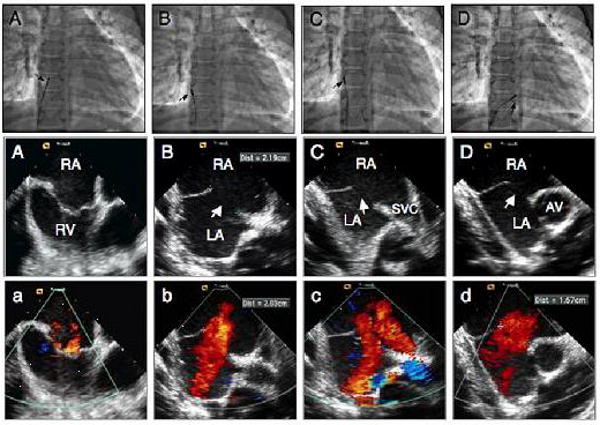
Fluoroscopic and intracardiac echocardiographic images during transcatheter closure of a large secundum atrial septal defect in a 12 year old male child. A, A, a position of the ICE catheter (arrow) during home view. B, B, b images in septal view without and with color Doppler demonstrating the presence of a large defect (arrow) measuring 22 mm. C, C, c, images in caval (long axis) view demonstrating the defect (arrow) and the rims. D, D, d, images in short axis view demonstrating the defect (arrow) and absence of anterior rim. RA: right atrium; RV: right ventricle; LA: left atrium; SVC: superior vena cava.
While the catheter is in the neutral position, rotating the posterior-anterior knob slightly posterior and the right-left knob slightly rightward, the transducer will face the interatrial septum (Figures 1 B,b). This view is called the septal view. In this position, the resulting fluoroscopic image showing the position of the ICE catheter is shown in Figure 1B. The echocardiographic images via ICE are shown in Figures 1B,b. In this view, the entire length of the atrial septum and the defect, the coronary sinus and the pulmonary veins are well seen. The latter can be seen in more or less detail depending on the exact location of the transducer.
After advancing the ICE catheter into a more cephalad location toward the superior vena cava (SVC), a view can be obtained which can be referred to as the SVC or “long-axis view” (Figures 1C,c). The resulting fluoroscopic images, showing the position of the catheter as well as corresponding echocardiographic images, are shown in Figures 1C,c. In this plane, the transducer faces the interatrial septum and the SVC can be seen as it relates to the right atrium. The interatrial septum is shown in a superior/inferior plane and corresponds to the TEE long axis view. Greater portions of the SVC can be seen as the ICE catheter is further advanced in this flexed position toward the SVC with slightly more rightward flexion. Greater portions of the inferior septum can similarly be imaged by withdrawing the ICE catheter toward the inferior vena cava. A defect in the interatrial septum (ASD/PFO) can be well profiled, and the superior and inferior rims as well as the diameter of the defect can be measured. In this view, both the right and left pulmonary veins may also be imaged, depending on the exact angle of the imaging plane. The imaging angle can be manipulated with clockwise and counterclockwise rotation as well as flexion/anteflexion in order to achieve these views.
After placing the ICE catheter into a locked position, the entire handle with the catheter shaft at the sheath hub is rotated clock-wise until it sits in a position with the transducer near the tricuspid valve annulus, and inferior to the aorta (Figures 1D,d). Minor adjustments of the posterior/anterior knob with less posterior flexion and more leftward rotation in the right-left knob can demonstrate the short axis view. A fluoroscopic image showing the catheter position and corresponding echocardiographic images are shown in Figures 1D,d. In this view, anatomic structures seen include the aortic valve in short axis and the interatrial septum (Figures 1D,d). This view is very similar to the basal short axis view obtained by TEE and is known as the “short axis view”. However, the right atrium is shown in the near field and the left atrium is in the far field, which is opposite of what is seen with TEE.
Prior to actual device deployment procedure, the above views are obtained in order to image the interatrial communication (ASD or PFO). Additional views can be obtained by advancing the catheter through the ASD or PFO into the left atrium, the so-called “views from the left heart”. Echocardiographic images from this location are equivalent to the transthoracic and TEE four chamber views. Anatomic structures seen in this view include the mitral valve, left ventricle (LV) and right ventricle (RV). The catheter can further be manipulated to view the left atrial appendage (LAA) that may be helpful in procedures to occlude the LAA. The catheter is then withdrawn back to the right atrium.
After imaging the intracardiac anatomy and assessment of the defect(s) and the rims as described above, ICE imaging can be used to measure the “stop-flow” diameter of the defect using the sizing balloon. The balloon can be viewed in either short or long axis view (Figure 2). After the defect was balloon sized, the device is loaded into the delivery sheath as has been described. All these steps can be monitored using ICE (Figure 3A-D).
Figure 2.
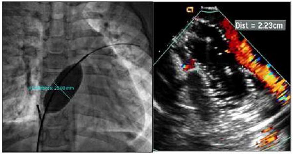
Cine fluoroscopic image and corresponding ICE image during balloon sizing of the defect. Left, cine fluoroscopy image demonstrating the balloon size of the defect. Right, ICE image during sizing indicating cessation of shunt.
Figure 3.
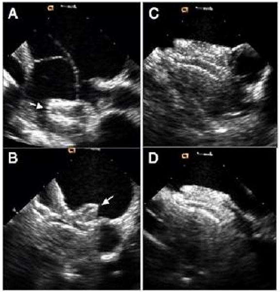
ICE images during various stages of device deployment. A, deployment of the left atrial desk. B, deployment of the right atrial desk in short axis. C, final device position in short axis view. D, final device position in long axis view
In cases of PFO closure to prevent recurrence of paradoxical embolism, we perform agitated saline contrast bubble study prior to device release and post device deployment.
Imaging Protocol for VSD Device Closure
Transcatheter closure of perimembranous ventricular septal defect (PmVSD) remains investigational in the US, therefore, experience using ICE in guiding device closure of PmVSD is very limited and we previously have reported on our experience (16). Briefly, after the ICE catheter is introduced into the mid right atrium as described above, we obtain the home view. In this view the perimembranous portion of the septum can be seen and the defect can be measured. To further delineate the size of the defect, we obtain the short axis view as described above. One may require slight adjustment using the posterior-anterior or right-left knobs. The VSD is well seen in this view. Once the appropriate size device is selected, the closure steps should be monitored by fluoroscopy and ICE.
Imaging Protocol for Pulmonary Valvuloplasty
One does not need ICE imaging for pulmonary valvuloplasty. However, in the occasional patient where fluoroscopy and or TEE/TTE imaging are not adequate due to weight, the introduction of ICE inside the right ventricle underneath the pulmonic valve will yield superb images of the valve (see supplemental material).
Imaging Protocol for Mitral Valvuloplasty
In cases of rheumatic mitral valve stenosis, balloon mitral valvuloplasty has become the treatment of choice. Many operators prefer to perform the trans-septal puncture and the valvuloplasty itself under echocardiographic guidance. Both TEE and TTE can be used to achieve this goal. However, the use of ICE to perform the septal puncture itself is more assuring than TTE. Furthermore, ICE does not require anesthesia. To perform the septal puncture, one can position the ICE catheter to obtain views of the septum (septal, short or long axis views). Once the puncture is performed and prior to the valvuloplasty, one needs to assess whether there is thrombus in the left atrial appendage, which would be a contraindication to going further. The next step is to assess the mitral valve before proceeding. This can be done by positioning the catheter in the right ventricle (as above) with some adjustment so that the transducer is directed towards the mitral valve. This position can be maintained during the interventional procedure itself. After the valvuloplasty, one needs to assess the gradient by CW Doppler and the presence/absence of mitral valve regurgitation using color Doppler. Diagnostic quality CW Doppler can be obtained using ICE devices (supplemental material).
Application of ICE for Guidance of EP Procedures
The ability to utilize imaging tools such as ICE and electroanatomical mapping have emerged as effective intra-procedural tools for ablative procedures.
ICE has emerged as a complementary tool to standard fluoroscopic imaging and an ideal modality for imaging structures highly relevant to catheter ablation procedures.
Transseptal Access
ICE is now well established in the intra-procedural guidance of transseptal catheterization. A central concept for transseptal catheterization involves the recognition of the fact that the true ‘inter-atrial’ portion of the septum is primarily the fossa ovalis. The flap of the fossa ovalis and the anterior rim of the limbus are the only atrial septal structures that are truly ‘inter-atrial’ (17). Other areas of the septum do not assure safe passage from the right to the left atrium. Entry into the aorta and the pericardial space pose extremely serious risks. The medial wall of the right atrium has several structures of anatomical significance. The fossa ovalis is immediately recognizable as a membranous structure. The right atrial aspect of the fossa shows a clear ridge (the limbus), which is not seen on the left atrial side of the septum. Aortic entry can occur if the needle is extended superior to the limbus. This results in entry of the needle into the transverse sinus and perforation of the aorta. It is critical to use echocardiographic imaging, pressure and contrast injection/staining of structures before advancing sheaths into the presumed left atrium (this remains one of the most avoidable complications in transseptal procedures). Pericardial effusions and tamponade also result from aortic entry due to the interposed transverse sinus. Further there is an added risk of entry into the ascending and descending aorta via the LA as the aorta wraps around the atrium. Several variants of this region impact transseptal catheterization, these include: lipomatous hypertrophy, fibrosis (which is noted in redo transseptal procedures) (11) and interatrial septal aneurysms. Further the presence of a persistent left superior vena cava also makes left atrial access challenging mainly by the deformation of the medial right atrial wall by the large coronary sinus. The fossa ovalis and these anatomic variants are instantly recognizable on intracardiac echocardiography and this imaging modality can facilitate safe transseptal puncture (18, 19). Further, ICE is invaluable for special areas of transseptal access such as radiofrequency assisted septal puncture (20).
Catheter Ablation of Arrhythmias
Atrial fibrillation
The true atria are normally thin walled structures (∼4 mm); however the atrial wall can become thinner and taper (2.0 mm) near the atrioventricular grooves. There is considerable anatomic heterogeneity with respect to atrial thickness within the anterior, superior (dome), posterior and lateral portions of the left atrium (21, 22). There exists a complex anatomical relationship between the posterior left atrium, pericardium (23), transverse and oblique sinuses, and adjacent structures such as the, aorta (24) and the esophagus. During catheter ablation procedures involving the superior and posterior left atrium, any one of these structures may be inadvertently damaged. The pulmonary veins (PVs) are posterior structures and have muscle sleeves that surround them (21). Phased array ICE imaging has been very useful for locating pulmonary veins and to ensure ablative lesions are placed on the atrial side of pulmonary vein left atrial junction. ICE has been used effectively to guide antral isolation procedures for atrial fibrillation (25). In this setting, ICE has been used to titrate energy delivery by monitoring microbubbles (26). Further, in this setting ICE imaging has been shown to be superior to using electrophysiological indices such as impedance monitoring to identify sites that are safe to ablate (27). Determination of wall thickness using ICE has the potential to help with lesion assessment during catheter ablation (28).
Monitoring for Complications and Avoiding Collateral Damage
One of the most valuable roles of ICE in the EP lab is to monitor for pericardial effusions, and it is an integral part of working up any hemodynamic instability during catheter ablation procedures (29). The esophagus poses a considerable challenge when ablating left atrial myocardium due to its close relationship to the posterior wall. A catastrophic complication of left atrial ablation is the risk of an atrioesophageal fistula formation (30). ICE has been used effectively for identification of the esophagus during the procedure (31, 32). Coronary arterial location can also be well defined by the use of ICE during interventional procedures (see supplemental material)(33).
Emerging Uses
Percutaneous Intrapericardial Echocardiography with ICE Catheters
Limitations of ICE include limited visualization of some structures due to the close distance of the ICE catheter to these endocardial structures, relative instability of ICE catheter images, and catheter related interference (22). Recently, percutaneous intrapericardial cardiac echo (PICE) has been performed in patients undergoing epicardial catheter ablation. PICE images provide views of the heart from the pericardial sinuses, and PICE is a safe and effective method for imaging relevant cardiac structures during EP procedures that involve pericardial access. This approach provides real time, high resolution imaging of structures not typically or easily seen with conventional ICE and also provides improved image stability over conventional ICE due to reduced catheter-to-catheter interference (see supplemental material). PICE is less limited by near field artifacts as compared to ICE, since the catheter sits outside the heart. Image stability is also improved because the catheter is held in place in part by its position in the transverse or oblique sinuses. Further wall motion on PICE has also been shown to correlate well with voltage mapping data (34, 35).
Intra-Coronary Sinus ICE
ICE imaging within the CS provides unique views of the mitral valve and clear views of the left atrium. The anatomical location of the coronary sinus within the oblique sinus of the pericardium allows the acquisition of views equivalent to pericardial imaging described above. ICE catheters have been shown to be effective for characterizing the mitral isthmus (36), atrioventricular groove vessels, and intra-CS muscle bundles (37), coronary arterial tree and mitral valve apparatus (38).
Future Advances in ICE: Forward Looking Devices, Merging Mapping, Imaging and Therapy
Higher Resolution
Given continued growth of complexity of EP procedures and the increased use of multi-detector CT for image merging and mapping, additional efforts at advancing intracardiac echo will be demanded to limit radiation exposure for patients who may have multiple procedures for arrhythmia treatment and/or resynchronization therapy with lead placements. Our research group has applied the tissue Doppler strain capabilities and the expanded field of view of our first device, the side-looking Hockeystick catheter, for modeling resynchronization therapy. The entire left ventricle in cross-section can often be viewed from the right atrium, and the high frame rate, high-resolution images are more than adequate for 2D strain computations to assess regional synchrony (Figures 4, 5 and 6).
Figure 4.
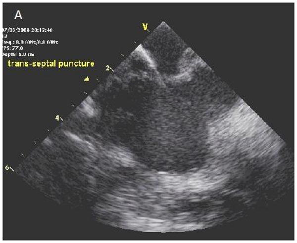
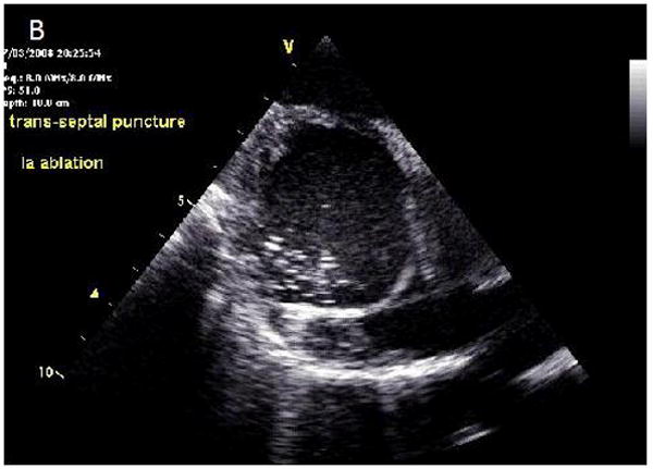
ICE images of transseptal catheterization using electrocautery. A, B, Progression from initiation of RF energy until puncture through the interatrial septum. LA = left atrium; RA = right atrium.
Figure 5.
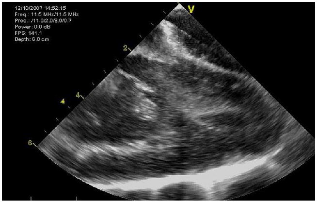
The entire LV of a 50kg pig can be imaged with the side-looking Hockeystick catheter device.
Figure 6.
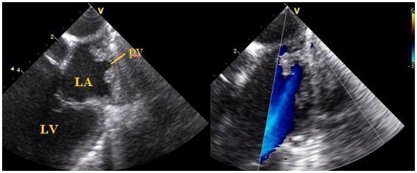
Two views of the superior portion of the left atrium, imaged from the left pulmonary artery during a pig study, show pulmonary vein entry and flow signals.
We have also developed a forward-looking microlinear array catheter which carries a port alongside the array for a radiofrequency (RF) wire to merge imaging and therapy into the same device (Figures 7-9).
Figure 7.
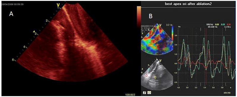
Image shows ablation of the RV apex imaged with the forward looking 9Fr, microlinear array develop by our BRP. A, the contact area becomes bright and blood speckle becomes more prominent; B, monitoring of strain rate at the apex during the same ablation with diminished longitudinal strain in the area being ablated.
Figure 9.
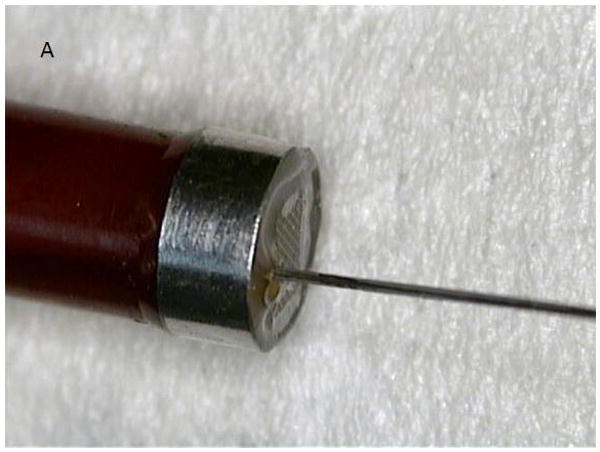
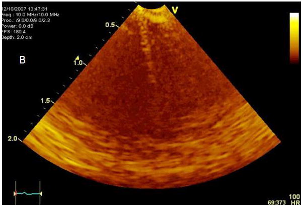
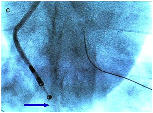
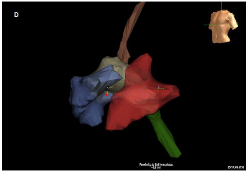
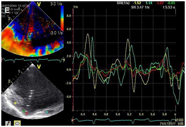
A. Modified microlinear catheter with an ablation wire coming through its face. B. Imaging of the wire contacting the surface of the LV- after retrograde passage of the imaging catheter. C. Fluoroscopic image of the catheter tip and the protruding wire. D. NavX (St Jude Medical) map of the catheter tip and the ablation site in the LV. E. Strain rate imaging of the area ablated. The area in contact with the ablation wire is thinned and retracted with decreased regional strain deflection.
Expected advances include higher resolution and frequency agility from the integration of computer micromachined ultrasound transducers (cMUTs), which represent the next generation of ultrasound technology. They are more reproducible and more flexible than piezoelectric ceramic, and can be made from masks like integrated circuits, so they are extremely reproducible. Flex circuit bonding on the back of the array and the DC bias that tenses the silicon cup, much like a timpani drum, allow significant frequency agility and, equally important, just before collapse of the membrane against the bottom of the cup the amplitude of emission goes up substantially. Hence, much as the efforts of applying high intensity focused ultrasound (HIFU) to cancer therapy under MRI guidance, we have shown that our forward-looking cMUT arrays can potentially be used for delivering HIFU energy imaging and therapy from the same array.
EP Enabled Devices for Imaging and Therapy
A number of groups are undertaking further efforts at integration of ultrasound imaging with electroanatomical mapping technologies, fusion and overlay images, as shown in Figure 10, where the ultrasound image from a known location based on tracking the position of the scanning catheter with electrofield imaging sensors, such as NavX (St. Jude Medical), can be placed as an overlay onto the electroanatomical map, also showing the position of other EP or ablation catheters within the heart and the EP recordings and propagation maps. This requires additional electrodes on the side looking Hockey Stick array: two ring electrodes proximal and distal to the array, and additional electrode with a gap- so that the Electrofield Navigation can determine which way the array is facing in rotational space. For the forward looking microlinear array this has also been achieved with the addition of two electrodes near the tip (39).
Figure 10.
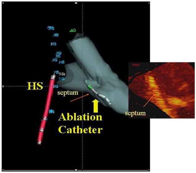
Fusion image showing the ultrasound image of ablation overlaid onto the NavX (St. Jude Medical) shell with a retrograde ablation catheter ablating the left side of the septum, which has brightened. This also requires reading the rotational position of the side-looking Hockeystick catheter into the electrofield NavX (St. Jude Medical) milieu.
4D Intracardiac Imaging Devices
The final advances will be integration of 4D ultrasound intracardiac imaging. Early efforts at pullback of rotational devices have produced 4D intracardiac maps, as has rotation of side-looking devices like the ICE devices (40). Both approaches require gating and spatial localization and are reconstructions rather than real time approaches.
An example of a 4D reconstructed image is shown (Figure 11), but it will be side-looking matrix arrays wrapped around the side of a catheter scanning an arc in 3D space, or forward-looking 4D devices that will most likely be applicable for providing real time intracardiac guidance for imaging interventions.
Figure 11.
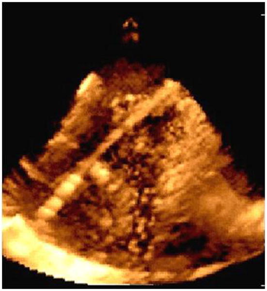
Imaging with a prototype real time 3D ICE system in experimental animals: image of an ablation catheter in the RV from the right atrium.
In our efforts, a forward-looking cMUT ring array is functioning in prototype fashion on a printed circuit board, and has been shown to derive 4D imaging of targets in a water tank (Figure 12). The bonding and flex circuits necessary to prepare the ring array for catheter implementation are underway.
Figure 12.
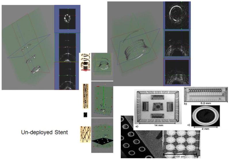
cMUT ring array architecture, flip chip integrated circuits bonded on the back of the ring array and 3D imaging of wire targets.
The ring array, which is a 9 Fr device, also equipped with electrodes for electrofield NavX (St. Jude Medical) integration, can scan a cone of information to image internal surfaces within the heart out to 4-7 cm. The device has a 5 Fr lumen so that a laser fiber, or an RF fiber, or an additional core of cMUTs, or an EP ablation catheter can be placed through the lumen and its positioning and activity can be observed in real time.
New Ultrasound Transducer Technologies for Providing Imaging and Therapy
Another direction being explored for image fusion for EP and arrhythmia therapy, and perhaps the most elegant, relate to integration of EP with MRI. Halperin and colleagues in Baltimore (41-43) and the group headed by Demoulin in Boston have been separately working in these areas and have prepared MRI compatible ablation devices which have reduced heat generation and can actually be visualized with an RF antenna for localization (44,45). They can be used to guide ablation in 3D space using real-time MRI and validate the effectiveness of ablation therapies by late gadolinium (41-43).
A number of electrophysiologists and MRI specialists are working in interventional MRI to prepare MRI-compatible versions of our forward-looking microlinear array devices so that they can be localized within an MRI milieu, provide ultrasound visualization of the surface to be ablated and add real-time ultrasound monitoring to the MRI imaging of the EP ablation.
It is likely that these more advanced 3D devices will find their place in other aspects of transcatheter therapeutics, including ASD device closure, coronary sinus based devices for non-surgical mitral annuloplasty, and catheter based repair procedures for mitral regurgitation which, even in the face of real-time 3D transesophageal echocardiography, will allow extreme near field and accurate visualization of 3D anatomy without requiring the general anesthesia necessitated by esophageal intubation for these long procedures.
Summary
ICE technology is already being developed commercially, and within our BRP program, which specifically targets EP guidance and therapy with integrated devices, the evolution of these devices towards higher levels of performance and use of cMUT arrays to yield 4D ICE will advance diagnostic application and guidance of transcatheter therapies for heart disease.
Supplementary Material
Figure 8.
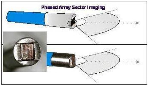
Diagram and photograph of the forward looking microlinear array catheter. Computer micromachined solid state ultrasound array, mounting and backing.
Acknowledgments
Funding: This research was partially funded by NHLBI grant R01 HL67647, “High frequency ultrasound arrays for cardiac imaging”.
Footnotes
Conflicts: The research considered was partially funded by R01 HL67647, “High frequency ultrasound arrays for cardiac imaging”, a Bioengineering Research Partnership grant in which GE Global Research and IBI/St. Jude's Medical are Partnerships. There are no other potential conflicts.
All authors have read and agreed to this manuscript as written.
References
- 1.Cieszynski T. Intracardiac method for the investigation of structure of the heart with the aid of ultrasonics. Arch Immun Ther Exper. 1960;8:551–557. [PubMed] [Google Scholar]
- 2.Kimoto S, Omoto R, Tsunemoto M. Ultrasonic tomography of the liver and detection of heart atrial septal defect with the aid of ultrasonic intravenous probes. Ultrasonics. 1964;2:82. [Google Scholar]
- 3.Kossoff G. Diagnostic application of ultrasound in cardiology. Aust Radiol. 1966;10:101–106. doi: 10.1111/j.1440-1673.1966.tb00774.x. [DOI] [PubMed] [Google Scholar]
- 4.Eggleton RC, Townsend C, Kossoff G. Computerized ultrasonic visualization of dynamic ventricular configuration. 8th ICMBE; July 1969; Session 10-3. [Google Scholar]
- 5.Bom N, Lancée CT, Van Egmond FC. An ultrasonic intracardiac scanner. Ultrasonics. 1972;10:72–76. doi: 10.1016/0041-624x(72)90250-8. [DOI] [PubMed] [Google Scholar]
- 6.Bom N, ten Hoff H, Lancée CT, Gussenhoven WJ, Bosch JG. Early and recent intraluminal ultrasound devices. Int J of Cardiac Imag. 1989;4:79–88. doi: 10.1007/BF01745137. [DOI] [PubMed] [Google Scholar]
- 7.Ludomirsky A, Ricou F, Weintraub R, Sahn DJ. Applications of intravascular scanning in congenital heart disease. In: Tobis JM, Yock P, editors. Intravascular Ultrasound Imaging, Chapter 20. Churchill Livingstone Publisher; New York, NY: 1992. pp. 247–252. [Google Scholar]
- 8.Pandian NG, Kreis A, Brockway B, Isner JM, Sacharoff A, Boleza E, Caro R, Muller D. Ultrasound Angioscopy: Real-time, two-dimensional, Intraluminal ultrasound imaging of blood vessels. Am J Cardiol. 1988;62:493–494. doi: 10.1016/0002-9149(88)90992-7. [DOI] [PubMed] [Google Scholar]
- 9.Pandian NG, Kreis A, Weintraub A, Motarjeme A, Desnoyers M, Isner JM, Konstam M, Salem DN, Millen V. Real-time intravascular ultrasound imaging in humans. Am J Cardiol. 1990;65:1392–1396. doi: 10.1016/0002-9149(90)91334-3. [DOI] [PubMed] [Google Scholar]
- 10.Valdes-Cruz LM, Sideris E, Sahn DJ, Murillo-Olivas A, Knudson O, Omoto R, Kyo S, Gulde R. Transvascular intracardiac applications of a miniaturized phased-array ultrasonic endoscope: Initial experience with intracardiac imaging in piglets. Circulation. 1991;83:1023–1027. doi: 10.1161/01.cir.83.3.1023. [DOI] [PubMed] [Google Scholar]
- 11.Seward JB, Packer DL, Chan RC, Curley M, Tajik AJ. Ultrasound cardioscopy: Embarking on a new journey. Mayo Clin Proc. 1996;71:629–635. doi: 10.1016/S0025-6196(11)62999-6. [DOI] [PubMed] [Google Scholar]
- 12.Seward JB, Khandheria BK, McGregor CG, Locke TJ, Tajik AJ. Transvascular and intracardiac two-dimensional echocardiography. Echocardiography. 1990;7:457–464. doi: 10.1111/j.1540-8175.1990.tb00386.x. [DOI] [PubMed] [Google Scholar]
- 13.Hellenbrand WE, Fahey JT, McGowan FX, Weltin GG, Kleinman CS. Transesophageal echocardiographic guidance of transcatheter closure of atrial septal defect. Am J Cardiol. 1990;66:207–213. doi: 10.1016/0002-9149(90)90590-w. [DOI] [PubMed] [Google Scholar]
- 14.Hijazi ZM, Wang Z, Cao QL, Koenig P, Waight D, Lang R. Transcatheter closure of atrial septal defects and patent foramen ovale under intracardiac echocardiographic guidance: feasibility and comparison with transesophageal echocardiography. Cathet Cardiovasc Interven. 2001;52:194–199. doi: 10.1002/1522-726x(200102)52:2<194::aid-ccd1046>3.0.co;2-4. [DOI] [PubMed] [Google Scholar]
- 15.Koenig PR, Abdulla RI, Cao QL, Hijazi ZM. Use of intracardiac echocardiography to guide catheter closure of atrial communications. Echocardiography. 2003;20:781–787. doi: 10.1111/j.0742-2822.2003.03039.x. [DOI] [PubMed] [Google Scholar]
- 16.Cao QL, Zabal C, Koenig P, Sandhu S, Hijazi ZM. Initial clinical experience with intracardiac echocardiography in guiding transcatheter closure of perimembranous ventricular septal defects: feasibility and comparison with transesophageal echocardiography. Cathet Cardiovasc Interven. 2005;66:258–267. doi: 10.1002/ccd.20463. [DOI] [PubMed] [Google Scholar]
- 17.Anderson RH, Webb S, Brown NA. Clinical anatomy of the atrial septum with reference to its developmental components. Clin Anat. 1999;12:362–374. doi: 10.1002/(SICI)1098-2353(1999)12:5<362::AID-CA6>3.0.CO;2-F. [DOI] [PubMed] [Google Scholar]
- 18.Marcus GM, Ren X, Tseng ZH, Badhwar N, Lee BK, Lee RJ, Foster E, Olgin JE. Repeat transseptal catheterization after ablation for atrial fibrillation. J Cardiovasc Electrophysiol. 2007;18:55–59. doi: 10.1111/j.1540-8167.2006.00657.x. [DOI] [PubMed] [Google Scholar]
- 19.Daoud EG, Kalbfleisch SJ, Hummel JD. Intracardiac echocardiography to guide transseptal left heart catheterization for radiofrequency catheter ablation. J Cardiovasc Electrophysiol. 1999;10:358–363. doi: 10.1111/j.1540-8167.1999.tb00683.x. [DOI] [PubMed] [Google Scholar]
- 20.Bidart C, Vaseghi M, Cesario DA, Mahajan A, Fujimura O, Boyle NG, Shivkumar K. Radiofrequency current delivery via transseptal needle to facilitate septal puncture. Heart Rhythm. 2007;4:1573–1576. doi: 10.1016/j.hrthm.2007.07.008. [DOI] [PubMed] [Google Scholar]
- 21.Ho SY, Sanchez-Quintana D, Cabrera JA, Anderson RH. Anatomy of the left atrium: implications for radiofrequency ablation of atrial fibrillation. J Cardiovasc Electrophysiol. 1999;10:1525–1533. doi: 10.1111/j.1540-8167.1999.tb00211.x. [DOI] [PubMed] [Google Scholar]
- 22.Becker AE. Left atrial isthmus: anatomic aspects relevant for linear catheter ablation procedures in humans. J Cardiovasc Electrophysiol. 2004;15:809–812. doi: 10.1046/j.1540-8167.2004.03651.x. [DOI] [PubMed] [Google Scholar]
- 23.D'Avila A, Scanavacca M, Sosa E, Ruskin JN, Reddy VY. Pericardial anatomy for the interventional electrophysiologist. J Cardiovasc Electrophysiol. 2003;14:422–430. doi: 10.1046/j.1540-8167.2003.02487.x. [DOI] [PubMed] [Google Scholar]
- 24.Cury RC, Abbara S, Schmidt S, Malchano ZJ, Neuzil P, Weichet J, Ferencik M, Hoffmann U, Ruskin JN, Brady TJ, Reddy VY. Relationship of the esophagus and aorta to the left atrium and pulmonary veins: implications for catheter ablation of atrial fibrillation. Heart Rhythm. 2005;2:1317–1323. doi: 10.1016/j.hrthm.2005.09.012. [DOI] [PubMed] [Google Scholar]
- 25.Verma A, Marrouche NF, Natale A. Pulmonary vein antrum isolation: intracardiac echocardiography-guided technique. J Cardiovasc Electrophysiol. 2004;15:1335–1340. doi: 10.1046/j.1540-8167.2004.04428.x. [DOI] [PubMed] [Google Scholar]
- 26.Marrouche NF, Martin DO, Wazni O, Gillinov AM, Klein A, Bhargava M, Saad E, Bash D, Yamada H, Jaber W, Schweikert R, Tchou P, Abdul-Karim A, Saliba W, Natale A. Phased-array intracardiac echocardiography monitoring during pulmonary vein isolation in patients with atrial fibrillation: impact on outcome and complications. Circulation. 2003;107:2710–2716. doi: 10.1161/01.CIR.0000070541.83326.15. [DOI] [PubMed] [Google Scholar]
- 27.Vaseghi M, Cesario DA, Valderrabano M, Boyle NG, Ratib O, Finn JP, Wiener I, Shivkumar K. Impedance monitoring during catheter ablation of atrial fibrillation. Heart Rhythm. 2005;2:914–920. doi: 10.1016/j.hrthm.2005.06.007. [DOI] [PubMed] [Google Scholar]
- 28.Ren JF, Callans DJ, Schwartzman D, Michele JJ, Marchlinski FE. Changes in local wall thickness correlate with pathologic lesion size following radiofrequency catheter ablation: an intracardiac echocardiographic imaging study. Echocardiography. 2001;18:503–507. doi: 10.1046/j.1540-8175.2001.00503.x. [DOI] [PubMed] [Google Scholar]
- 29.Bunch TJ, Asirvatham SJ, Friedman PA, Monahan KH, Munger TM, Rea RF, Sinak LJ, Packer DL. Outcomes after cardiac perforation during radiofrequency ablation of the atrium. J Cardiovasc Electrophysiol. 2005;16:1172–1179. doi: 10.1111/j.1540-8167.2005.50135.x. [DOI] [PubMed] [Google Scholar]
- 30.Pappone C, Oral H, Santinelli V, Vicedomini G, Lang CC, Manguso F, Torracca L, Benussi S, Alfieri O, Hong R, Lau W, Hirata K, Shikuma N, Hall B, Morady F. Atrioesophageal fistula as a complication of percutaneous transcatheter ablation of atrial fibrillation. Circulation. 2004;109:2724–2726. doi: 10.1161/01.CIR.0000131866.44650.46. [DOI] [PubMed] [Google Scholar]
- 31.Cummings JE, Schweikert RA, Saliba WI, Burkhardt JD, Brachmann J, Gunther J, Schibgilla V, Verma A, Dery M, Drago JL, Kilicaslan F, Natale A. Assessment of temperature, proximity, and course of the esophagus during radiofrequency ablation within the left atrium. Circulation. 2005;112:459–464. doi: 10.1161/CIRCULATIONAHA.104.509612. [DOI] [PubMed] [Google Scholar]
- 32.Ren JF, Marchlinski FE, Callans DJ. Real-time intracardiac echocardiographic imaging of the posterior left atrial wall contiguous to anterior wall of the esophagus. J Am Coll Cardiol. 2006;48:594. doi: 10.1016/j.jacc.2006.05.019. author reply 594-595. [DOI] [PubMed] [Google Scholar]
- 33.Vaseghi M, Cesario DA, Mahajan A, Wiener I, Boyle NG, Fishbein MC, Horowitz BN, Shivkumar K. Catheter ablation of right ventricular outflow tract tachycardia: value of defining coronary anatomy. J Cardiovasc Electrophysiol. 2006;17:632–637. doi: 10.1111/j.1540-8167.2006.00483.x. [DOI] [PubMed] [Google Scholar]
- 34.Horowitz BN, Vaseghi M, Mahajan A, Cesario DA, Buch E, Valderrabano M, Boyle NG, Ellenbogen KA, Shivkumar K. Percutaneous intrapericardial echocardiography during catheter ablation: a feasibility study. Heart Rhythm. 2006;3:1275–1282. doi: 10.1016/j.hrthm.2006.07.025. [DOI] [PubMed] [Google Scholar]
- 35.Tude Rodrigues AC, d'Avila A, Houghtaling C, Ruskin JN, Picard M, Reddy VY. Intrapericardial echocardiography: a novel catheter-based approach to cardiac imaging. J Am Soc Echocardiogr. 2004;17:269–274. doi: 10.1016/j.echo.2003.10.024. [DOI] [PubMed] [Google Scholar]
- 36.West JJ, Norton PT, Kramer CM, Moorman JR, Mahapatra S, DiMarco JP, Mangrum JM, Mounsey JP, Ferguson JD. Characterization of the mitral isthmus for atrial fibrillation ablation using intracardiac ultrasound from within the coronary sinus. Heart Rhythm. 2008;5:19–27. doi: 10.1016/j.hrthm.2007.08.029. [DOI] [PubMed] [Google Scholar]
- 37.Cesario DA, Valderrabano M, Cai JJ, Ji S, Shannon KM, Weiss JN, Wiener I, Olshansky B, Chen PS, Shivkumar K. Electrophysiological characterization of cardiac veins in humans. J Interv Card Electrophysiol. 2004;10:241–247. doi: 10.1023/B:JICE.0000026919.49412.93. [DOI] [PubMed] [Google Scholar]
- 38.Celigoj A, Cesarion D, Mahajan A, Koppula A, Horowitz BN, Tobis J, Boyle N, Sahn D, Shivkumar K. Intra-coronary sinus echocardiography: a new approach to guide cardiac interventional procedures. J Am Coll Cardiol. 2007;49S:133A–134A. [Google Scholar]
- 39.Okumura Y, Henz BD, Johnson SB, Bunch TJ, O'Brien CJ, Hodge DO, Altman A, Govari A, Packer DL. Multimodality image mapping system methods, quantitative validation, and clinical feasibility of a novel three-dimensional ultrasound for image-guided mapping and intervention. Circ Arrhythmia Electrophysiol. 2008;1:110–119. doi: 10.1161/CIRCEP.108.769935. [DOI] [PubMed] [Google Scholar]
- 40.Seward JB. Fantastic voyage through the cardiovascular system. Eur J Echocardiogr. 2004;5:8–11. doi: 10.1016/j.euje.2003.11.005. Editorial Comment. [DOI] [PubMed] [Google Scholar]
- 41.Dong J, Dickfeld T, Dalal D, Cheema A, Vasamreddy CR, Henrikson CA, Marine JE, Halperin HR, Berger RD, Lima JA, Bluemke DA, Calkins H. Initial experience in the use of integrated electroanatomic mapping with three-dimensional MR/CT images to guide catheter ablation of atrial fibrillation. J Cardiovasc Electrophysiol. 2006;17:459–466. doi: 10.1111/j.1540-8167.2006.00425.x. see comment. [DOI] [PubMed] [Google Scholar]
- 42.Dickfeld T, Kato R, Zviman M, Lai S, Meininger G, Lardo AC, Roguin A, Blumke D, Berger R, Calkins H, Halperin H. Characterization of radiofrequency ablation lesions with gadolinium-enhanced cardiovascular magnetic resonance imaging. J Am Coll Cardiol. 2006;47:370–378. doi: 10.1016/j.jacc.2005.07.070. [DOI] [PMC free article] [PubMed] [Google Scholar]
- 43.Dickfeld T, Calkins H, Zviman M, Meininger G, Lickfett L, Roguin A, Lardo AC, Berger R, Halperin H, Solomon SB. Stereotactic magnetic resonance guidance for anatomically targeted ablations of the fossa ovalis and the left atrium. J Interven Cardiac Electrophysiol. 2004;11:105–115. doi: 10.1023/B:JICE.0000042348.13084.04. [DOI] [PubMed] [Google Scholar]
- 44.Erhart P, Ladd ME, Steiner P, Heske N, Dumoulin CL, Debatin JF. Tissue-independent MR tracking of invasive devices with an internal signal source. Magn Res Med. 1998;39:279–284. doi: 10.1002/mrm.1910390215. [DOI] [PubMed] [Google Scholar]
- 45.Feng L, Dumoulin CL, Dashnaw S, Darrow RD, Guhde R, Delapaz RL, Bishop PL, Pile-Spellman J. Transfemoral catheterization of carotid arteries with real-time MR imaging guidance in pigs. Radiology. 2005;234:551–557. doi: 10.1148/radiol.2341031951. [DOI] [PubMed] [Google Scholar]
Associated Data
This section collects any data citations, data availability statements, or supplementary materials included in this article.


