Bioengineered tissues, like native tissues, are inherently multiscale and derive their macroscopic mechanical properties from the complex interaction among their underlying microstructural components. These components form the extracellular matrix (ECM) and are organized at multiple scales to provide both function to the tissue as a whole (centimeter scale) and to provide a supportive and functional environment for the constituent cells (micrometer scale). Mechanical interactions at the tissue scale are not only governed by the microstructure but are also communicated through the matrix to the cells. Such stimulation can lead to microstructural remodeling and adaptation of the tissue to the mechanical environment and has important implications for successful tissue engineering strategies [1].
To understand, predict, and engineer a tissue with appropriate mechanical properties, it is essential that we understand how the underlying structure determines the macroscopic behavior. Numerous approaches to the problem of predicting tissue-level behavior based on microscopic architecture have been considered, including empirical macroscopic models of collagen [2] and tissues [3]–[5] and fiber–composite models [6]–[10]. An important challenge in using any microstructure-based model is the specification of the model. Fortunately, advances in polarized light imaging [11], [12], small-angle light scattering [13], [14], and confocal microscopy [15] provide the opportunity to get structural information, either through a distribution of fiber orientations or statistical measures of fiber orientation. The potential thus exists to use orientation data in a detailed model.
Such information has been incorporated previously into the structural constitutive models [16], which have shown that the range in mechanical response and material constants is largely attributed to the variability in tissue microstructure [16], [17]. Consequently, complex fiber rearrangements during mechanical testing must be quantitatively measured to ensure proper model formulation and prediction validation [16].
Any model that considers fiber mechanics must account for fiber kinematics. The assumption that fibers deform affinely with the macroscopic deformation is common but is not accurate for a fiber network [18], [19]. Previous work in our group has used a network-of-springs model described later and in more detail elsewhere [20]-[22], which captures the structure and the network behavior well for a single-constituent material (e.g., collagen).
In this study, we compared experimentally measured fiber network kinematics and the macroscopic mechanical response from cell-compacted, cross-shaped collagen gels (cruciforms) [23], with the predictions from our multiscale modeling technique [22]. The macroscopic finite element model matched the physical dimensions and boundary conditions of the experimental cruciform to be modeled. Different microscale network models were constructed for each finite element that matched fiber microstructure described by maps of the local direction and strength of alignment obtained from polarimetric alignment imaging. The outputs of the multiscale model included the macroscopic load-deformation response and the microscopic (fiber) kinematics.
Methods
Sample Preparation
Collagen gels were reconstituted from acid-extracted bovine patellar tendon collagen. The collagen solution was neutralized with 3% (4-(2-hydroxyethyl)-1-piperazineethanesulfonic acid (HEPES), 12.2% 0.1 N NaOH, 10% 10× minimum essential medium (MEM), 6% fetal bovine serum (FBS), 0.1% penicillin/streptomycin (P/S), 0.1% fungizone, and 1% l-glutamine. Gels were made to an initial collagen concentration of 1.5 mg/mL and a cell concentration of 0.5 × 10⁶ cells per milliliter (neonatal human dermal fibroblasts). Gels were cast into cross-shaped Teflon molds (cruciforms) that differed in arm width aspect ratio (Figure 1). The horizontal arm width was 8.0 mm, and the vertical arm width was 4.0 mm. Velcro strips at the end of each arm allowed collagen attachment to the mold. Collagen cruciforms were cured for 1 h in a humidified 95%/5% air/CO2 incubator maintained at 37 °C, before the culture medium was added. Culture medium consisted of high-glucose Dulbecco's modified eagle's medium (DMEM) supplemented with 10% FBS, 1% antibiotic/antimycotic, 2.5 μg/mL amphotericin B, 2 μg/mL insulin, 50 μg/mL ascorbic acid, and 1 ng/mL transforming growth factor beta (TGF-β). The medium was replaced every three days. The gels were cultured for four weeks before mechanical testing to allow compaction, which stiffens and aligns the gel in a manner dependent on the cruciform mold geometry and reduces the gel volume by approximately 95% [23]. Details on the change in geometry that arises from the cell-driven compaction in the cruciform can also be found in [23].
Fig. 1.
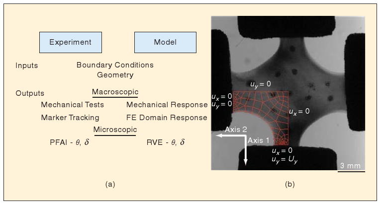
(a) Scheme for model formulation and comparison to experiments. The model is constructed to match the collagen cruciform at both the macroscopic and microscopic level. (b) The finite element domain matches the initial configuration and boundary conditions, and networks match the initial local alignment direction (θ) and alignment strength (δ). The model's predictive success is assessed by comparing its output to the measurements at each stage of the strip-biaxial test.
Mechanical interactions at the tissue scale are not only governed by the microstructure but are also communicated through the matrix to the cells.
Polarimetric Fiber Alignment Imaging
Polarimetric fiber alignment imaging (PFAI) allows real-time measurement of the local direction and strength of fiber alignment in native tissues and in collagen- and fibrin-based bioartificial tissues during mechanical testing [23]–[25]. PFAI relies on the direction-dependent refractive index or birefringence of collagen fibers. When polarized light is transmitted through a sample, its amplitude and phase changes in response to the sample composition. Elliptically polarized light passing through the sample and analyzed with a linear polarizer at successive angles produces a sinusoidal oscillation in intensity of the transmitted light. The pixel-wise change in amplitude and phase indicates the local strength and the direction of fiber alignment, respectively. In the ideal case, a location in which the fiber orientation is isotropic has no change in intensity and, thus, zero retardation (i.e., δ = 0). As fiber alignment increases within a sample, so does δ. However, retardation is dependent on a variety of factors, including fiber density and sample thickness, and, as such, is only capable of providing a relative measure of fiber alignment strength.
PFAI measurements were made using an optic train consisting of a fiber optic source, a linear polarizer, a quarter wave plate, the sample, a rotating linear polarizing sheet, a rotating stepper motor, a zoom lens, and a charged coupled device (CCD) camera. The sample was mounted on an Instron planar biaxial testing unit. During mechanical testing, intensity images were generated that corresponded to the pixel-wise birefringence of the sample. With the assumption that collagen fibers act as strong linear retarders, harmonic analysis of the images gives the average angle of the fiber orientation (θ) and retardation (δ) at each pixel [12], [24].
Biaxial Testing
Mechanical testing was conducted with an Instron planar biaxial testing unit in a manner similar to that described in [23]. Cruciforms were removed from the molds and tested at 25 °C in a phosphate buffered saline (PBS) bath. Each arm was held in place with adjustable compression grips attached to a 5-N load cell and positioned in line with the PFAI system. Mechanical characterization of the gels included strip-biaxial extension, also known as an off-axis hold test. The wider arms, which were oriented along the horizontal axis, remained stationary, whereas the narrower arms were displaced along the vertical axis at a rate of 8 mm/min and to a final stretch ratio of 1.35. Before the test, Verhoeff's stain was applied at discrete points on the cruciform surface to measure local displacements for comparison with model simulations.
Multiscale Model
The multiscale modeling technique employed here is based on volume averaging theory and has been applied previously to hydrated collagen gels, vascular tissues, and synthetic fibrous biomaterials [22], [26], [27]. In this model, the Galerkin finite element method is used for the macroscopic (tissue-level) problem, but instead of a constitutive equation to relate the deformation to the stress, a microscopic network problem is solved at the points where the stress is needed to get the finite element solution. The collagen is modeled by a three-dimensional (3-D) fiber network contained within a representative volume element (RVE). The RVEs are centered at the integration points of the finite element model, and their boundary displacements are determined by the macroscopic deformation field through the finite element basis functions. Deformation of the RVE boundaries is translated through fiber cross-links at the boundaries into forces in the network. Therefore, a force balance among the fibers determines the equilibrium network forces. To calculate the macroscopic stress, volume averaging theory is used, according to which the macroscopic stress tensor is given as the volume average of the local network stresses, which are expressible in terms of the fiber forces. Finally, the averaged stress balance at the macroscale is solved to determine the macroscopic displacement field, and the procedure iterates until convergence. Thus, by solving a set of microstructural problems simultaneously, the tissue-level behavior can be related directly to the fiber mechanics and the network structure.
Macroscopic (Finite Element) Mesh
Because of the symmetry of the experiment, only one quadrant of the cruciform was modeled. First, a finite element mesh was created to match the macroscopic geometry. An image of the preloaded cruciform was imported into Solidworks, where one quadrant was traced and extruded to match the shape and thickness of the sample, respectively. The resulting solid representation was exported as a parasolid model and imported into the preprocessor GAMBIT, where it was meshed into 89 hexahedral finite elements with one element through the thickness.
Microscopic Collagen Networks
In previous studies, we have generated a small number of collagen networks that were used throughout the macroscopic domain. This work represents a departure in that we created a unique network for each element based on the initial geometry of the cruciform. To accomplish this task, a mask was created that corresponded to the area above which each finite element overlapped the cruciform in the PFAI intensity image. The mask was then used to determine the average angle and average retardation associated with each element, which was then used to create a representative network for each element.
Fiber network orientation (projected in the XY plane) can be described with a length-weighted, second-rank orientation tensor, Ω,
| (1) |
where li is the length of fiber i, θi is the angle fiber i makes with respect to the horizontal, and the sum is over all the fibers in the network. The eigenvalues and eigenvectors of Ω correspond to the magnitudes and principal directions of fiber orientation, respectively, and the trace of Ω must be equal to one. The average angle from the PFAI is easily converted to a principal direction, but the relationship between the retardation and strength of alignment is unclear. In the ideal limit, retardation is proportional to the ratio of the orientation anisotropy [21]. The proportionality is dependent on the concentration, composition, and other factors, which are assumed to be homogeneous throughout the sample, so that
| (2) |
where C is the lumped constant of proportionality, δ* is the scaled retardation (0 ≤ δ* ≤ 1), ω1 and ω2 are the eigenvalues of Ω, and ω1 ≤ ω2. Under this convention, an isotropic network has a δ* value of zero, and a completely aligned network has a δ* value of unity. The raw retardation was scaled by C = 242° to produce an initial set of slightly aligned networks with an average δ* = 0.26 ± 0.06.
The data from PFAI represent values projected from a 3-D microstructure, and the networks are created so that their projections match. Histology and scanning electron images of comparable cruciforms have shown that the collagen fibers are predominantly oriented in the plane after gel compaction. The model networks were therefore generated with predominantly planar alignment, with eigenvalues associated with the z-direction set approximately to 0.1.
Fiber networks were generated by a custom MATLAB routine that allowed specification of fiber number, eigenvalues of the orientation tensor, and preferred direction [18], [22], [28]. Briefly, a number of seed points were generated randomly. Each seed point possessed its own randomly generated direction vector, whose components were scaled by the PFAI eigenvalues and ω3 ≅ 0.1. A seed point was selected randomly and grown a unit length along its direction vector. If fiber growth extended beyond the boundaries of a predefined volume, growth was terminated, and the fiber was repositioned to the boundary. If fiber growth resulted in contact with another fiber, the fibers were joined, and a cross-link was formed. This process continued until all fibers either met a boundary or formed a cross-link. After the network had been formed, a smaller network was extracted from a box that bounded the central region of the larger network (cf. [29]). Fibers were defined as the segment between two nodes, where a node was a point of fiber termination either at a cross-link or at a boundary. The nodes were modeled as pin joints that were free to rotate but unable to slip.
To assess how well the network matches the PFAI data, the unit eigenvectors of Ω were compared to the PFAI eigenvectors. The network was considered aligned with the PFAI measurement if the magnitude of the dot product of the major eigenvectors exceeded 0.99. Otherwise, the difference in angle was used to rotate the larger network, and a new network from the inner box was extracted and compared. All networks created contained between 300 and 350 fibers.
Model Formulation
The multiscale model uses three equations: an equation to describe the mechanical behavior of the individual fiber, an equation for deriving the macroscopic stress from the network forces, and an equation for the macroscopic stress balance. Collagen fibers are strong in tension but weak in compression. Forces from bending or fiber–fiber interactions were considered negligible compared with those generated by fiber stretch. The phenomenological constitutive equation proposed by Billiar and Sacks [30] and recast in terms of the force, F, on a fiber is given as
| (3) |
where Ef and B are constitutive constants, Af is the cross-sectional area of the collagen fiber, and εf is the Green's strain of the fiber and is calculated as , where λf is the fiber stretch ratio. At the low-strain limit, (3) becomes a linear model with elastic modulus Ef.
The macroscopic averaged Cauchy stress tensor, Sij, is calculated from the microscopic stress tensor, sij, through the theory of volume averaging [31], [32]
| (4) |
where V is the volume of a RVE containing a model network. By writing sij = skjδik and recognizing that ∇x = xi,j = δij, where x is the direction vector, (4) can be rewritten as
| (5) |
For microscopic equilibrium, skj,k = 0, and the divergence theorem gives
| (6) |
where tj is the traction on the RVE boundaries, and the integral is over the RVE surface. The discretized form of (6) [33],
| (7) |
gives the components of Sij in terms of the positions x and the forces F acting on those nodes.
Finally, the expression for the macroscopic stress balance [21] is given as
| (8) |
where u is RVE boundary displacement and n is the unit normal vector. The right-hand side (RHS) of (8) arises from the correlation between inhomogeneous displacement of the RVE boundary and local inhomogeneities in the stress field. In the case of a fixed RVE, the RHS would be zero.
Model Implementation
The finite element domain consisted of 89 elements (Figure 1), each containing eight Gauss points. The two surfaces attached to grips were fixed, and a symmetry boundary condition was applied to the two symmetry planes. The other surfaces of the finite element domain were stress-free. The cruciform was displaced uniaxially to 2 mm in ten equal steps. At the end of each step, the nodal coordinates for each element and the network configurations were outputted to text files for analysis.
Even though the macroscopic problem involves fewer than 700 degrees of freedom, the computational demands for the solution of the microscopic problem were considerable. The model consisted of 712 RVEs—the number of finite elements times the number of Gauss points per element—and each RVE involved approximately a thousand degrees of freedom—the number of nodes, two of which define a fiber, multiplied by three degrees of freedom. Therefore, more than 700,000 degrees of freedom were involved in the total problem. To address the computational demands, the microscopic problem was parallelized using the message passing interface (MPI) technique as described elsewhere [22]. For the simulations presented here, up to 30 processors were used, and the wall time did not exceed 25 min.
Comparison of Model and Networks
The goal of our multiscale model is to capture both the macroscopic and the microscopic behavior. Macroscopic behavior was examined by measuring the force on both grips during the strip-biaxial test and by tracking the edge of the sample and fiduciary points. Microscopic behavior was examined by comparing the PFAI results to the model-predicted fiber kinematics, averaging over each finite element. To facilitate comparison, two quantities are introduced. Δθ is the difference between the average fiber alignment direction measured by the PFAI and the average orientation of the fibers predicted by the model. Similarly, Δδ* is the difference between the scaled retardation measured by PFAI and the predicted anisotropy, that is, the difference in the projected network's eigenvalues. Consequently, δ* is taken as a measure of network anisotropy and is referred to as such throughout the remainder of this article.
Results
Macroscopic Response
The macroscopic mechanical response of the cruciform under strip-biaxial loading was typical of soft tissues—a long, extensible toe region followed by an exponential and then linear increase in force (Figure 2). The vertical axis (Axis 1) reached a peak load of 0.41 N at a grip displacement of 2.0 mm, which corresponded to a stretch ratio λ = 1.35. The horizontal axis (Axis 2), which remained stationary during the test, developed a maximum load of 0.05 N. The parameters used in (3) for the model to fit the data were A = EfAf = 2.64 × 10⁻⁶ N and B = 4. Assuming an average fiber diameter of 90 nm gives Ef = 415 MPa. The model produced a similar response to the experiment but underpredicted the nonlinearity in both directions.
Fig. 2.
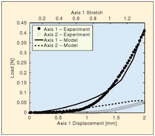
Comparison of macroscopic mechanical response. The load response of the experiment (circular markers) and the model (lines) is plotted for each loading axis as a function of displacement along the vertical axis (Axis 1). The vertical arms of the cruciform are each displaced 2 mm in 15 s, whereas the horizontal arms of the cruciform remained stationary.
The boundary displacements were matched at the grip to specify the problem. During deformation, the finite element domain stretched to satisfy the boundary conditions, leaving the curved surface of the cruciform free to deform because of network restructuring occurring in each element. As the cruciform stretched, the free surface contracted inward. The free surface of the model matched this behavior through a displacement of 1.4 mm (λ = 1.2). At larger stretches, the finite element domain did not contract inward as much as the experiment.
Regional differences in displacement were assessed by tracking fiduciary markers on the surface of the cruciform (Figure 3). Displacements were greater along the vertical axis than along the horizontal axis. The displacement of equivalent points in the model was underpredicted in the x direction and overpredicted in the y direction. The greatest difference between the predicted and measured displacement, , occurred at full extension for Marker 3, Δd = 0.44 mm, and Marker5, Δd = 0.49 mm.
Fig. 3.
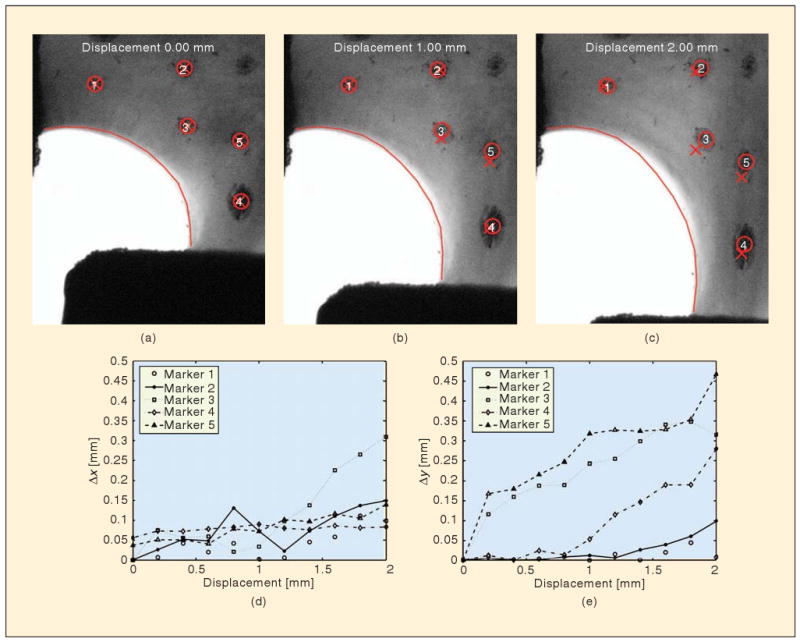
Comparison of local displacements. Verhoeff's stain placed at discrete points on the cruciform surface was tracked (circle) during the mechanical test and compared to the equivalent location in the finite element domain (X). The absolute difference in x and y position between the model and experiment for each step is depicted in the plots. The finite element domain along the free surface (solid line) did not contract as much as the experiment once displacements greater than 1.4 mm occurred.
Microscopic Response
Typical model results showing fiber restructuring within RVEs are given in Figure 4. The RVEs were initially cubic in shape, representing an 8-μm cube around the integration points. As the sample was stretched, networks in different regions were affected differently. Near the horizontal grips (Element A in Figure 4), the model predicted relatively little deformation, with the RVE domain remaining roughly square when projected to a two-dimensional (2-D) view. Near the center of the sample (Element B), in contrast, the nearly uniaxial stretching led to the vertical elongation of the RVE and vertical alignment of the fibers in the network. Along the sample-free boundary (Element C), the stretch along a line roughly 45° from the horizontal is equivalent to simple shear, leading to a parallelogram shape for the deformed RVE.
Fig. 4.
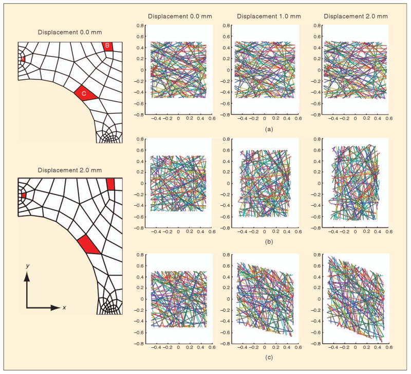
Network behaviors in the model. Depicted are the projections of three different RVE networks (a)–(c) from integration points in the highlighted elements in the finite element domain (red). Over the course of the deformation, the RVEs deformed from their initial square shape to different shapes based on the multiaxial deformation field that developed.
Before loading, the RVE networks were created to match the cruciform's microstructure (〈Δθ〉 = 2.7° ± 2.2°, 〈Δδ*〉 = 0.05 ± 0.04). Because of the mechanical constraints imposed on the gel during the compaction process, the fibers aligned with the cruciform's arms and parallel to the free surface of the cruciform's body (Figure 5). Alignment strength decreased toward the interior of the cruciform. Alignment in the central region favored the horizontal direction because of more cells exerting traction in the wider cruciform arm.
Fig. 5.
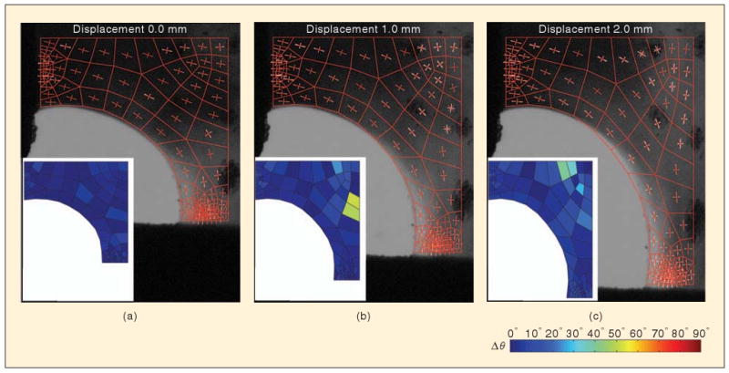
Comparison of model and networks. Images show model domain and network orientation (red) overlaid on fiber orientation as measured by PFAI (white). Inset shows the difference between the principal direction of model and the experimental measures averaged over each finite element. (a) Initially, the model matches the experiment by construction. After (b) 1 mm and (c) 2 mm of vertical displacement, the network realigns, as predicted by the model and observed experimentally.
During loading, a complex rearrangement of the cruciform's microstructure occurred. The microstructure rotated and stretched toward the vertical direction. For the most part, the model kinematics matched those of the cruciform. The largest discrepancy in alignment direction occurred at d = 2.0 mm (〈Δθ〉 = 7.6° ± 6.5°). A few regions did develop high values of Δθ (Figure 5), but these regions were also areas where the microstructural anisotropy was relatively low (Figure 6); hence, θ was not well defined. For example, the maximum value of Δθ (Δθ = 83.5°) occurred at a grip displacement d = 1.60 mm, where the anisotropy for the experiment and network were δ* = 0.05 and 0.02, respectively.
Fig. 6.
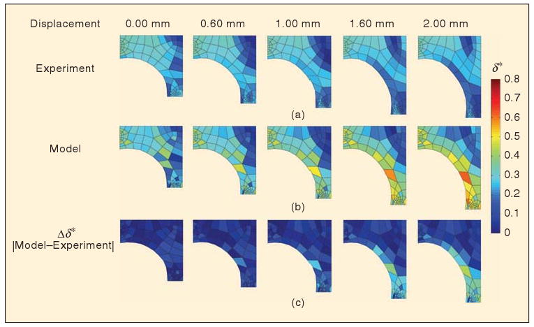
Comparison of fiber network anisotropy (δ*). The spatial variation in the anisotropy is depicted for the experiment (a) and the model (b) based on the area of each finite element. Blue regions are weakly aligned (or isotropic) and correspond to a low value of δ*. The absolute difference in anisotropy between the model and the experiment (c) shows discrepancies developing at the cruciform's free surface and in the vertical arm at later grip displacements.
As the cruciform was stretched vertically, the isotropic region in the center of the cruciform expanded outward (Figure 6). This behavior occurred because the microstructure, which was initially aligned in the horizontal direction, passed through a point of isotropy on its way toward developing vertical alignment. Once the microstructure was recruited in the vertical direction, the anisotropy increased, and the region of isotropy propagated along Axis 2 toward the horizontal grip. The model captured this behavior well. The model also predicted that vertical alignment in the vertical arm of the cruciform would increase with stretch, but the experiments indicated that a growing region of isotropy developed in the interior of the vertical arm near the grip. Consequently, at later grip displacements, the largest differences in model predictions occur along the cruciform's free surface and in the vertical arm.
Discussion
Although continuum-level models [3], [4], [8]–[10] are important for understanding the interactions between the cells and the surrounding matrix, they cannot account for the specific contributions of the underlying fiber network to the macroscopic behavior. There has been considerable work on structural models [6], [22], [34], but specification and testing of such models are a significant challenge. In this work, a model for an anisotropic, inhomogeneous fibroblast-populated collagen gel was constructed and specified based on PFAI. The model was then used to simulate a strip-biaxial test, and the model and the experimental results were compared by three different metrics.
Macroscopic force-stretch relations: The model showed significantly less “toeing” than the experiment, with overprediction of the force on both grips at low strain. The poor performance of the model at low strains may be due to an inaccuracy in (3), which does not account explicitly for crimping [30] or the “lock-out” effect [35], which produces nonlinear microscopic-scale behavior that is sharper than can be captured by (3). That the problem is at the fiber level rather than the network or macroscopic level is supported by the observation that the model correctly predicted the anisotropy in the material response and underpredicted the curvature of both force traces in Figure 2.
Macroscopic-scale kinematics: The shape of the free edge of the cruciform was monitored, as were displacements of fiduciary points drawn on the sample. The model was in good agreement with the experiment with respect to the free-edge kinematics (Figure 3), easily outperforming an isotropic model (not shown), but it showed less good agreement for internal point displacements, with errors of up to 0.49 mm for a 2-mm grip displacement. In particular, for points near the moving grip (bottom right of images in Figure 3), the model overpredicted the displacement, suggesting that the model overpredicts the stiffness of the highly aligned arm regions relative to the more isotropic belly region. This difference could be due to the model assumption of free rotation at fiber cross-links, which is a lower bound on the effect of the cross-links. A more detailed microstructure and cross-link model could provide a better picture.
Collagen fiber kinematics: The model showed an excellent agreement with the experiment on both the degree and direction of alignment for most of the sample, correctly matching the leftward shift in the isotropic region near the belly of the sample (Figure 6). A notable exception was the failure of the model to predict a decrease in fiber alignment observed near the lower grip. Whether this failure is related to the overprediction of macroscopic kinematics is not clear.
On the basis of these three metrics, we conclude that within the scope of this study, the PFAI-based microstructural model performed acceptably, capturing the anisotropy and inhomogeneity of the tissue as well. There are, however, a number of issues that could be addressed in future studies and merit further discussion here.
PFAI provides a quantitative measure of alignment, and the principal direction of alignment is easily obtained from the extinction angle, but the degree of alignment is more difficult to relate to the microstructural organization because of differences in the sample thickness, concentration, composition, and other factors affecting sample optical properties, such as confounding form birefringence effects [36]. In this work, to relate retardation to network anisotropy, we assumed that the retardation was proportional to the difference between the eigenvalues of the orientation tensor (cf. [21], [36]). The proportionality constant accounts for the issues previously stated that were not directly quantified in this study but requires an assumption that the cruciform is homogeneous with respect to these effects. Consequently, δ* should only be interpreted as a relative measure of alignment strength within a given sample. In reality, the collagen density is likely heterogeneous because of different levels of compaction, particularly at the boundaries where less compaction has been seen compared to the interior in other collagen gel geometries [37]. Additional work will be required to accommodate material heterogeneity, such as density and thickness, in the measurement. Further, because the PFAI provides only 2-D information, an assumption about the third dimension was required. Scanning electron micrographs taken on vertical sections of fibrin-based cruciforms show that the cruciform microstructure is mostly planar, which is expected when cruciforms are constrained in the plane but permitted to compact through their thickness. As a result, we estimated that Ω33 = 0.1 for all networks in the model. This simplification, although convenient and not unreasonable, clearly requires further study. Thus, although the PFAI-based model was successful and the advantages of PFAI are many, care must be taken to recognize that the generation of the PFAI-based model is limited by the accuracy of the initial microstructure prescribed by PFAI.
Our kinematic comparisons were based on marker tracking for dots drawn on the sample with Verhoeff's stain. The calculated motion is thus sensitive to spreading of the stain over time, image noise, shading, and any other factors that affect calculation of the centroid of the marker or the validity of the centroid as a material point. Only a few markers were used because their presence interferes with PFAI measurements. Marker area was not excluded from the calculation of average angle and retardation, and, as a result, the anisotropy for some elements may be underpredicted. The network anisotropy measured for finite elements along the free surface was also underestimated at later displacements where agreement between the experiment and the model began to deviate and some of the background entered into the measurement.
An additional concern with the current study is the handling of the sample. The sample was cut free from its mold and contracted rapidly because of residual stress from the cells within. The sample was positioned in the grips and then stretched along both axes until a small load (∼0.03 N) registered on each load cell. This retraction and stretching could have caused artifacts in the fibers, such as crimping or bending of fibers, not accounted for in the constitutive equation (3) that could contribute to the imperfect match between the model and experiment, especially in light of the large toe region. Under the current testing methodology, gripping the sample and returning it to its configuration in the mold is challenging. Efforts are underway to redesign the mold so that the samples can be tested directly without the need for excision.
Conclusions
Successful implementation of a multiscale model will provide a basis for rational design of engineered tissues and augment our understanding of structure–function relationships in native tissues. The current representation of microstructure remains simplistic but captures the most important mechanical properties of the network.
Acknowledgments
Support for this work was provided by the National Institutes of Health (1 R01 EB005813-01 and 1 F32 EB007433-01A1). The authors thank Paul Robinson and Choon-Sik Jhun for technical assistance with the PFAI and Instron equipment.
Biographies

Edward A. Sander received his B.S. degree in chemical engineering from the University of Texas at Austin, in 2000. He earned the M.Eng. and Ph.D. degrees in biomedical engineering from Tulane University, New Orleans, Louisiana, in 2004 and 2006, respectively. His doctoral work focused on understanding the interplay between tissue biomechanics and cellular remodeling as it relates to the onset of glaucomatous damage in the optic nerve head. He is currently a postdoctoral fellow of the National Institutes of Health (NIH) National Research Service Award (NRSA) in the Department of Biomedical Engineering at the University of Minnesota, in Minneapolis. His research interests include tissue engineering, biomechanics, and multiscale modeling of biopolymer gels, tissue analogs, and tissues.

Triantafyllos Stylianopoulos received his diploma in chemical engineering from National Technical University of Athens, Greece, in 2003. He earned the Ph.D. degree in chemical engineering from the University of Minnesota, in Minneapolis, in 2008. He is currently a postdoctoral fellow in the Edwin L. Steele Laboratory for tumor biology, Department of Radiation Oncology at Harvard Medical School and Massachusetts General Hospital, Boston, Massachusetts. His research interests include the study of transport of fluid and nanoparticles through the interstitial space of tumors, vascular network formation in normal and tumor tissue, and mathematical modeling.

Robert T. Tranquillo received his Ph.D. degree in chemical engineering from the University of Pennsylvania in 1986. He was a North Atlantic Treaty Organization (NATO) postdoctoral fellow at the Center for Mathematical Biology at Oxford for one year before beginning his appointment in the Department of Chemical Engineering and Materials Science at the University of Minnesota in 1987. He has served as the head of the new Department of Biomedical Engineering since its inception in 2000. More recently, his research program has focused on the role of cell behavior in cardiovascular and neural tissue engineering applications. His research has resulted in 70 peer-reviewed publications. He is a fellow of the American Institute of Medical and Biological Engineering and the Biomedical Engineering Society, and a Distinguished McKnight University Professor.

Victor H. Barocas received his B.S. degree in chemical engineering (1988) and M.S. degree in chemical engineering practice (1989) from the Massachusetts Institute of Technology (MIT) and a Ph.D. degree in chemical engineering (1996) from the University of Minnesota. He is currently a professor of biomedical engineering at the University of Minnesota. His research interests include tissue engineering, tissue mechanics, and ocular bioengineering.
References
- 1.Guilak F, Butler DL, Goldstein SA, Mooney DJ. Functional Tissue Engineering. New York: Springer-Verlag; 2003. [Google Scholar]
- 2.Haut RC, Little RW. A constitutive equation for collagen fibers. J Biomech. 1972;5(no 5):423–430. doi: 10.1016/0021-9290(72)90001-2. [DOI] [PubMed] [Google Scholar]
- 3.Shoemaker PA, Schneider D, Lee MC, Fung YC. A constitutive model for two-dimensional soft tissues and its application to experimental data. J Biomechanics. 1986;9(no 9):695–702. doi: 10.1016/0021-9290(86)90193-4. [DOI] [PubMed] [Google Scholar]
- 4.Barocas VH, Tranquillo RT. An anisotropic biphasic theory of tissue-equivalent mechanics: The interplay among cell traction, fibrillar network deformation, fibril alignment, and cell contact guidance. J Biomech Eng. 1997 May;119:137–145. doi: 10.1115/1.2796072. [DOI] [PubMed] [Google Scholar]
- 5.Driessen NJ, Bouten CV, Baaijens FP. A structural constitutive model for collagenous cardiovascular tissues incorporating the angular fiber distribution. J Biomech Eng. 2005 June;127:494–503. doi: 10.1115/1.1894373. [DOI] [PubMed] [Google Scholar]
- 6.Layton BE, Sastry AM. A mechanical model for collagen fibril load sharing in peripheral nerve of diabetic and nondiabetic rats. J Biomech Eng. 2004 Dec;126:803–814. doi: 10.1115/1.1824118. [DOI] [PubMed] [Google Scholar]
- 7.Layton BE, Sastry AM. Equal and local-load-sharing micromechanical models for collagens: Quantitative comparisons in response of non-diabetic and diabetic rat tissue. Acta Biomater. 2006;2(no 6):595–607. doi: 10.1016/j.actbio.2006.05.013. [DOI] [PubMed] [Google Scholar]
- 8.Breuls RG, Sengers BG, Oomens CW, Bouten CV, Baaijens FP. Predicting local cell deformations in engineered tissue constructs: A multilevel finite element approach. J Biomech Eng. 2002 Apr;124:198–207. doi: 10.1115/1.1449492. [DOI] [PubMed] [Google Scholar]
- 9.Ferrenq I, Tranqui L, Vailhe B, Gumery PY, Tracqui P. Modelling biological gel contraction by cells: Mechanocellular formulation and cell traction force quantification. Acta Biotheor. 1997 Nov;45:267–293. doi: 10.1023/a:1000684025534. [DOI] [PubMed] [Google Scholar]
- 10.Gasser TC, Ogden RW, Holzapfel GA. Hyperelastic modelling of arterial layers with distributed collagen fibre orientations. J R Soc Interface. 2006;3(no 6):15–35. doi: 10.1098/rsif.2005.0073. [DOI] [PMC free article] [PubMed] [Google Scholar]
- 11.Tower TT, Tranquillo RT. Alignment maps of tissues. I. Microscopic elliptical polarimetry. Biophys J. 2001 Nov;81:2954–2963. doi: 10.1016/S0006-3495(01)75935-8. [DOI] [PMC free article] [PubMed] [Google Scholar]
- 12.Tower TT, Tranquillo RT. Alignment maps of tissues. II. Fast harmonic analysis for imaging. Biophys J. 2001 Nov;81:2964–2971. doi: 10.1016/S0006-3495(01)75936-X. [DOI] [PMC free article] [PubMed] [Google Scholar]
- 13.Kronick PL, Sacks MS. Quantification of vertical-fiber defect in cattle hide by small-angle light scattering. Connect Tissue Res. 1991;27(no 1):1–13. doi: 10.3109/03008209109006991. [DOI] [PubMed] [Google Scholar]
- 14.Sacks MS, Smith DB, Hiester ED. A small angle light scattering device for planar connective tissue microstructural analysis. Ann Biomed Eng. 1997 July/Aug;25:678–689. doi: 10.1007/BF02684845. [DOI] [PubMed] [Google Scholar]
- 15.Voytik-Harbin SL, Roeder BA, Sturgis JE, Kokini K, Robinson JP. Simultaneous mechanical loading and confocal reflection microscopy for three-dimensional microbiomechanical analysis of biomaterials and tissue constructs. Microsc Microanal. 2003 Feb;9:74–85. doi: 10.1017/S1431927603030046. [DOI] [PubMed] [Google Scholar]
- 16.Sacks MS. Incorporation of experimentally-derived fiber orientation into a structural constitutive model for planar collagenous tissues. J Biomech Eng. 2003 Apr;125:280–287. doi: 10.1115/1.1544508. [DOI] [PubMed] [Google Scholar]
- 17.Sacks MS, Chuong CJ. Orthotropic mechanical properties of chemically treated bovine pericardium. Ann Biomed Eng. 1998 Sept/Oct;26:892–902. doi: 10.1114/1.135. [DOI] [PubMed] [Google Scholar]
- 18.Chandran PL, Barocas VH. Affine versus non-affine fibril kinematics in collagen networks: Theoretical studies of network behavior. J Biomech Eng. 2006 Apr;128:259–270. doi: 10.1115/1.2165699. [DOI] [PubMed] [Google Scholar]
- 19.Sastry AM, Cheng X, Wang CW. Mechanics of stochastic fibrous networks. J Thermoplast Comp Mater. 1998;11(no 3):288–296. [Google Scholar]
- 20.Agoram B, Barocas VH. Coupled macroscopic and microscopic scale modeling of fibrillar tissues and tissue equivalents. J Biomech Eng. 2001 Aug;123:362–369. doi: 10.1115/1.1385843. [DOI] [PubMed] [Google Scholar]
- 21.Chandran PL, Barocas VH. Microstructural mechanics of collagen gels in confined compression: Poroelasticity, viscoelasticity, and collapse. J Biomech Eng. 2004;126(no 2):152–166. doi: 10.1115/1.1688774. [DOI] [PubMed] [Google Scholar]
- 22.Stylianopoulos T, Barocas VH. Volume-averaging theory for the study of the mechanics of collagen networks. Comput Methods Appl Mech Eng. 2007;196(no 31–32):2981–2990. [Google Scholar]
- 23.Jhun C, Evans MC, Barocas VH, Tranquillo RT. Fiber reorientation in planar biaxial loading of bioartificial tissues possessing prescribed alignment. Ann Biomed Eng. doi: 10.1115/1.3148194. submitted for publication. [DOI] [PMC free article] [PubMed] [Google Scholar]
- 24.Tower TT, Neidert MR, Tranquillo RT. Fiber alignment imaging during mechanical testing of soft tissues. Ann Biomed Eng. 2002 Nov/Dec;30:1221–1233. doi: 10.1114/1.1527047. [DOI] [PubMed] [Google Scholar]
- 25.Neidert MR, Tranquillo RT. Tissue-engineered valves with commissural alignment. Tissue Eng. 2006 Apr;12:891–903. doi: 10.1089/ten.2006.12.891. [DOI] [PubMed] [Google Scholar]
- 26.Stylianopoulos T, Barocas VH. Multiscale, structure-based modeling for the elastic mechanical behavior of arterial walls. J Biomech Eng. 2007 Aug;129:611–618. doi: 10.1115/1.2746387. [DOI] [PubMed] [Google Scholar]
- 27.Stylianopoulos T, Bashur CA, Goldstein AS, Guelcher SA, Barocas VH. Computational predictions of the tensile properties of electrospun fiber meshes: Effect of fiber diameter and fiber orientation. J Mech Behav Biomed Mater. 2008;1(no 4):326–335. doi: 10.1016/j.jmbbm.2008.01.003. [DOI] [PMC free article] [PubMed] [Google Scholar]
- 28.Sander EA, Barocas VH. Comparison of 2D fiber network orientation measurement methods. J Biomed Mater Res A. 2009 Feb;88(no 2):322–331. doi: 10.1002/jbm.a.31847. [DOI] [PubMed] [Google Scholar]
- 29.Clague DS, Phillips RJ. A numerical calculation of the hydraulic permeability of three-dimensional disordered fibrous media. Phys Fluids. 1997;9(no 6):1562–1572. [Google Scholar]
- 30.Billiar KL, Sacks MS. Biaxial mechanical properties of the native and glutaraldehyde-treated aortic valve cusp: Part II—A structural constitutive model. J Biomech Eng. 2000 Aug;122:327–335. doi: 10.1115/1.1287158. [DOI] [PubMed] [Google Scholar]
- 31.Drew DA. Averaged field equations for two-phase media. Stud Appl Math. 1971;L(no 2):133–166. [Google Scholar]
- 32.Nemat-Nasser S, Hori M. Micromechanics: Overall Properties of Heterogeneous Materials. 2nd. Amsterdam: North Holland; 1999. [Google Scholar]
- 33.Oda M, Iwashita AA. Mechanics of Granular Materials. Rotterdam: Brookfield; 1999. [Google Scholar]
- 34.Wang CW, Berhan L, Sastry AM. Structure, mechanics and failure of stochastic fibrous networks: Part I––Microscale considerations. J Eng Mater Technol. 2000;122(no 4):450–468. [Google Scholar]
- 35.Bischoff JE, Arruda EM, Grosh K. A rheological network model for the continuum anisotropic and viscoelastic behavior of soft tissue. Biomech Model Mechanobiol. 2004 Sept;3:56–65. doi: 10.1007/s10237-004-0049-4. [DOI] [PubMed] [Google Scholar]
- 36.Fuller GG. Optical Rheometry of Complex Fluids. New York: Oxford Univ Press; 1995. [Google Scholar]
- 37.Evans MC, Barocas VH. Complex mechanical constraints generate complex alignment in compacting collagen-based engineered tissues. Ann Biomed Eng. submitted for publication. [Google Scholar]


