

I. INTRODUCTION
Our efforts on droplet interface bilayers in Oxford began in the summer of 2005 following a suggestion made by David Needham at “Lipids, liposomes and biomembranes”, a conference in Vancouver. He proposed that a bilayer would form between two droplets brought together in an oil (squalene) containing a lipid (glycerol monooleate) and that this might be a means to miniaturize planar bilayer recording. It was immediately apparent that, if it were realized, the approach would have many intriguing facets providing, for example, the ability to build droplet networks [Fig. 1(a)]. All we had to do was prove it, and by October 2005 we had our first recordings. At the time, we didn’t realize that a pioneering study demonstrating bilayer formation in a similar system had been carried out in Moscow, published in 1966, but apparently not pursued further [Fig. 1(b)].1 And, in parallel with our studies, work on droplet interface bilayers was also initiated in Takeuchi’s laboratory.2
FIG. 1.

Origins of droplet interface bilayers. (a) Notes made soon after the meeting in 2005 showing possibilities including droplet networks. “Not much to it really, GMO/squalene and just make the micro or milli droplets, touch together and see if there’s a bilayer”, David Needham. (b) Device made by Tsofina and colleagues, and published in 1966, in which a bilayer is formed between two aqueous compartments in heptane containing phospholipids. Reprinted by permission from Macmillan Publishers Ltd: Nature 1966, 212, 681–683, copyright 1966.
Here, we review the advances that have already stemmed from the development of droplet interface bilayers (DIB) with examples taken largely from our own work. We have formed bilayers at droplet/droplet interfaces and various droplet/aqueous-surface interfaces, where the surfaces can include hydrogels. Others have formed bilayers between two aqueous volumes in a microfluidic device.2,3 Besides their utility as ultra-stable bilayers for single-channel recording, we have demonstrated applications including droplet networks for power generation and light sensing, droplet arrays for ion channel screening, coupled expression-analysis systems for ion channels and the examination of proteins in asymmetric bilayers. Bilayers formed at droplet/hydrogel interfaces (DHB) enable precise measurements of membrane properties, including specific capacitance and the lateral diffusion of lipids and membrane-bound proteins. The versatile DHB geometry enables additional applications. Following separation by electrophoresis, bands of protein can be assayed directly for ion channel activity. Further, blockers arrayed in hydrogels can be screened rapidly by sliding a DHB with an incorporated channel or pore across the surface of the gel. In a closing section, we speculate briefly on where this area of research might lead.
II. DROPLET INTERFACE BILAYERS: BASIC PRINCIPLES
A. Droplet interface bilayers: the two-droplet system
Planar bilayers, often created by using the classical Montal-Mueller (MM) method,4,5 have been used for decades as model systems to study the functional properties of ion channels and pores [Fig. 2(a)].6 But, the MM planar bilayer is a metastable structure that is delicate and short-lived,5 limiting its utility in conventional recording cells and microfluidic devices. With respect to stability, an important region is the annulus, which forms the interface between the 5-nm thick bilayer and the supporting macroscopic aperture located in a thin plastic barrier [shown in cross section, Fig. 2(a)]. The bulk of the annulus consists of an oil-lipid solution. Lipid exchange between the bilayer and the bulk aqueous phase and between the annulus and the bilayer, partitioning of the constituents of the oil phase into the aqueous phase (in the form of micelles) and the spread of the oil across the plastic barrier are all factors that combine to limit the lifetime and overall stability of MM bilayers. For example, the stability of planar bilayers with headgroups covalently attached to an encapsulating hydrogel is strongly correlated with stabilization of the annulus rather than the bilayer itself.11
FIG. 2.

Methods of bilayer formation: old versus new. (a) Montal-Mueller (MM) bilayers are created by folding the leaflets of two air/water lipid monolayers across an aperture ~100 μm in diameter in a Teflon film (typically 25-μm thick). This process takes minutes to learn but months to master. (b) By contrast, monolayers surrounding two droplets spontaneously snap together when brought into proximity. (c) By hanging the droplets on movable electrodes, droplet interface bilayers (DIB) can be made and pulled apart repeatedly. Conveniently, precise movement of one droplet with a micromanipulator also allows modulation of the bilayer area while the droplets are joined. These droplets are about 700 μm in diameter.
In the DIB approach, an aqueous droplet submerged under an oil-lipid mixture spontaneously acquires a coat comprising a self-assembled lipid monolayer (the “oil” is generally, but not limited to, a linear or branched hydrocarbon such as hexadecane or squalene). If two such droplets are brought into contact, the oil between the monolayers is displaced and a droplet-interface bilayer (DIB) forms [Fig. 2(b)]. Membrane proteins, dispersed inside one of the droplets, can become incorporated into the DIB. Electrodes within the droplets enable the application of a potential, as well as the measurement of ionic current flowing through embedded channels and pores [Fig. 2(c)]. Droplets can be created either by hand-pipetting aqueous solutions into the oil (in volumes reliably as low as 100 nL), or by using microfluidic junctions that combine oil/lipid and aqueous streams.
By contrast with MM bilayers, which usually have lifetimes of a few hours, the lifetimes of DIBs range from days to weeks, even under a continuously applied electrical potential. Although the origins of the relative stability of DIBs have yet to be precisely established, several factors distinguish this system from MM bilayers: (i) the interfacial forces acting on a DIB differ from those in the MM system;12 (ii) the DIB lacks an annulus and the surrounding oil, which replaces the annulus, cannot disperse; (iii) the supply of lipids to the DIB system is effectively inexhaustible; (iv) because the droplets are submerged under an incompressible oil, hydrostatic shock to the bilayer is minimized. For example, in a conventional bilayer apparatus, unilateral pressure on the bilayer can originate from a higher liquid level in one chamber than the other. Given the superior stability, and additional assets including low electrolyte volumes, the DIB approach has exceptional potential to simplify and accelerate investigations of ion transport.2,7–10
B. Proteins for DIBs
The means by which membrane proteins are incorporated into DIBs (and for that matter conventional bilayers) are of crucial importance and indeed require further development. Here, we summarize our findings with examples of both major structural classes of membrane proteins, i.e. α-helix bundles and β barrels [Table 1]. In addition, we have examined two smaller pore-forming molecules, viz. gramicidin (a non-ribosomal peptide) and nystatin (a polyene). In our so-far limited experience, the electrical properties of channels and pores in planar bilayers and DIBs are indistinguishable [Table 1].
Table 1.
| Protein/Class | Expression and purification | Droplet encapsulation | Electrical characterization |
|---|---|---|---|
| Staphylococcal α-hemolysin (αHL), heptameric protein pore/β barrel | Expressed by IVTT, or in E. coli or Staphylococcus aureus. For example, IVTT was followed by heptamerization on rRBCM and partial purification by SDS-PAGE. The protein was eluted from the gel with 10 mM Tris.HCl,1 mM EDTA, pH 8.0. A 100 μL IVTT reaction yields protein at around 2 to 4 μg/mL, which is diluted 1000 times in buffer (10 mM HEPES, 500 mM KCl, pH 7.0) before use. | Added as prepared to the droplet solution to a final concentration of 2 to 4 ng/mL. A range of pH values from 5 to 10 and salt concentrations from 150 to 2000 mM (NaCl or KCl) can be used. | Stepwise increases in current upon pore insertion (~800 pS in 1 M KCl, pH 7.0, at −50 mV). CDs are non-covalent blockers of the αHL pore that can be used to distinguish between αHL mutants. |
| OmpG, outer membrane protein G, a porin from E. coli/β barrel | Expressed in E. coli PC2889 cells and purified by SDS-PAGE. The OmpG extract was loaded onto a Q-Sepharose column and eluted with a 0 to 0.5 M NaCl gradient in denaturation buffer (50 mM Tris.HCl, pH 8.0, 8 M urea). Purified OmpG was refolded by dilution with refolding buffer (20 mM Tris.HCl, pH 9.0, 3.25% OG) until the final urea concentration reached 3.0 M. The protein was further diluted in the Tris.HCl buffer, but with 1.5% OG, to the working concentration of 1 ng/mL. | Used as a 1.5% OG solubilized monomer at a final concentration of 1 ng/mL. A range of pH values from 7 to 10 and salt concentrations from 200 to 2000 mM can be used. Insertion was driven by a high applied potential (e.g. +100 mV). | OmpG exhibits a conductance of 600 pS in 200 mM KCl at +50 mV. pH- dependent gating and voltage-dependent closure at above ±100 mV are observed. |
| Kcv, potassium channel from chlorella virus PBCV-1/α-helix bundle. | Expressed by IVTT in an E. coli S30 extract in which tetramers are formed. The tetramers were purified by SDS-PAGE and eluted from the gel with 10 mM HEPES, pH 7.4. The purified protein (2 to 4 μg/mL) was diluted before use in the same buffer to a working concentration of 2 to 4 ng/mL. | Used at a working concentration of ~4 ng/mL. The droplet contained 1 mM DPhPC (“lipid-in”) vesicles in 10 mM HEPES,100 to 500 mM KCl at pH 7.0. Insertion was driven by a high applied potential (e.g. +100 mV). | Kcv channels have unitary conductance values of 220 pS in 250 mM KCl at +100 mV. They are blocked by Ba2+ and quaternary ammonium salts |
| KcsA, potassium channel from Streptomyces lividans/α-helix bundle. | Expressed by IVTT in an E. coli S30 extract. The tetramers were purified by SDS-PAGE and eluted with 10 mM HEPES, pH 7.4. The purified protein was diluted before use in the same buffer to a working concentration of 10 ng/mL. | The tetramers were used at a final concentration of 10 ng/mL. The KCl concentration could be varied from 100 to 500 mM, and was buffered with 10 mM HEPES, pH 7.4, on the cis side and 10 mM succinic acid, pH 4.0, on the trans side. | Gating is observed at an applied potential of ±50 to±100 mV. The conductance of KcsA in 200 mM KCl, is 112 pS at an applied potential of +100 mV. The channels are blocked by Ba2+ and quaternary ammonium salts. |
| Bacteriorhodopsin (BR), light-driven proton pump from Halobacterium salinarium/α-helix bundle. | Purple membrane was solubilized in a 1:1 mixture of buffer (10 mM HEPES,100 mM NaCl, pH 7.5) and 0.01% (w/v) DDM in water, yielding a dark purple suspension. | To prepare BR-containing droplets, the stock DDM suspension was diluted 10- fold in 10 mM HEPES, 100 mM NaCl, pH 7.5. | BR transports one proton per photon of light absorbed, and hence BR that has been incorporated into a bilayer generates a current when illuminated. |
| Gramicidin A, a non- ribosomal peptide antibiotic from Bacillus brevis, which forms cation-selective channels. | Commercial material was dissolved in methanol. | Droplets were formed containing 1 mg/mL DPhPC lipid vesicles in 10 mM K phosphate, 1 M KCl, pH 7.0, with gramicidin (50 μg/mL). The mixture was diluted 1000- fold, before use in a lipid-out configuration. | At ±100 mV brief current steps are observed, resulting from the transient dimerization of the peptide. The conductance of gramicidin in the presence of1 M KCl is ~12 pS |
| Nystatin, a polyene antimycotic drug, which forms pores permeable to monovalent ions. | Commercial nystatin was dissolved in methanol (1 mg/mL) and kept in the dark. | Vesicles (1 mg/mL, 5:1:1:2 molar ratio of DOPE: DOPC: DOPG: ergosterol) were incubated with 50 μg/mL nystatin. Droplets were formed after a 1 to 1000 dilution into 10 mM K phosphate, 1000 mM KCl, pH7.0. The opposing droplet contained 150 mM KCl. | At ±200 mV, vesicle fusion events are marked by large spikes in the current that decay over several seconds. |
The proteins we have tested were prepared by various means and purified to differing extents. Most often we have expressed the protein by in vitro transcription and translation (IVTT) or in E. coli cells. For proteins made by IVTT, partial purification by SDS-PAGE is useful where the protein resists denaturation in the detergent sodium dodecyl sulfate. Examples that we have examined in this way include αHL heptamers, OmpG monomers, and Kcv and KcsA tetramers. K+ channel tetramers form spontaneously in E. coli S30 extracts, which we have found to be rich in lipids.
The proteins are eluted from the crushed polyacrylamide gel, usually by centrifugation through a spin filter, and most probably contain residual SDS, which keeps them in solution. The SDS-PAGE-purified proteins are diluted before use [Table 1], when the SDS concentration is presumably brought well below the CMC to a level at which it can neither break the bilayer, nor cause misleading artefacts in current recordings. Many detergents produce currents that mimic single channel behavior or cause considerable current “noise”. Consequently, it is essential to perform the necessary control experiments with the working detergent in the absence of protein. Proteins purified from E. coli cells, either directly or with a renaturation step, will also normally contain detergent at above the CMC and the same issues considered for IVTT proteins apply.
The low concentration of detergent in the protein samples appears to facilitate insertion into the bilayer, but it may be necessary to employ additional tricks to speed up the process. For example, in the case of OmpG, a high applied potential is required for efficient insertion. Often, the rate of insertion can be increased by manipulating the pH or salt concentration, but this is less desirable with DIBs as compared with conventional bilayers, because the conditions cannot easily be readjusted subsequently. In the case of BR [Table 1], the detergent treatment probably caused partial fragmentation and solubilization of the purple membrane (natural two-dimensional crystals of BR and lipid). Because the DIBs containing BR produced a strong unidirectional current upon illumination, it is likely that the purple membrane fragments inserted en bloc in a single orientation.13 In the cases of the antibiotics, gramicidin A and nystatin, no detergent was required as these pore-forming molecules are sufficiently soluble in water.
There is certainly scope for far more systematic studies of membrane protein insertion into intact bilayers including DIBs. In the case of conventional planar bilayers, we have recently developed approaches in which various probes carrying the protein of interest are brought into contact with the bilayer,14,15 and it seems likely that similar ideas could be extended to DIBs. For example, the agarose layer on the electrodes might be used as a source of protein.14 Additional means to bring proteins into preformed droplets are needed and might include droplet-droplet fusion or microinjection with a needle, as commonly used by electrophysiologists.
C. Properties of Droplet Interface Bilayers
Two distinct methods of forming droplet interface bilayers (DIBs) have been demonstrated: the “lipid-out” technique uses lipids dissolved in the oil phase as outlined above,2,7,8 whereas the “lipid-in” technique employs lipid vesicles in the internal aqueous phase [Fig. 3].16 Prior to bilayer formation, both methods require a stabilization period, which is much shorter for the lipid-in method (<5 min) than for the lipid-out technique (<30 min). In the lipid-out approach, the movement of droplets through the oil-lipid mixture, e.g., by gravity-driven flow, hastens the stabilization process.8 The physical mechanism governing stabilization is not understood at present. However, it is plausible that this period corresponds to the time required for monolayer formation.17 Another possibility is the formation of an organogel around the droplet.18 As evidenced below, we have demonstrated that stabilized droplets quickly form bilayers at their interfaces; within seconds after droplet contact, a variety of membrane proteins can insert into DIBs, where they exhibit electrical behavior identical to that seen in other bilayer platforms, e.g. planar MM bilayers.
FIG. 3.

Lipid-out and lipid-in DIB formation. (a) Lipid-out DIB formation. Aqueous droplets are pipetted onto agarose-coated Ag/AgCl electrodes and submerged in an oil-lipid solution. After a stabilization period to allow the droplets to become encased by monolayers, they are brought into contact and form a bilayer. (b) Lipid-in DIB formation. Two types of aqueous droplet, containing lipid vesicles of different compositions, are formed by injection into an oil reservoir. Vesicles fuse with the oil-water interface of each droplet and form monolayers. The droplets are then brought together to form an asymmetric bilayer. Adapted with permission from J. Am. Chem. Soc. 2008, 130, 5878–5879. Copyright 2008 Am. Chem. Soc.
In addition to their extended lifetimes of days to weeks, DIBs can, like conventional bilayers, withstand applied potentials of greater than 150 mV.7,8,16 Further, the positions of droplets can be controlled by attaching them directly to Ag/AgCl electrodes that are connected to micromanipulators. The tips of the electrodes are coated with agarose to render them hydrophilic, which causes unsupported droplets to hang from the ends of the electrodes instead of falling off them.7,8 Pushing two droplets together, or pulling them apart, enables precise modulation of the area of a DIB, which is helpful for single-channel studies. For example, initially, the bilayer area can be made large to maximize the probability of channel insertion; after insertion, the area can be reduced to decrease the chance of further incorporation.10
In addition, we have found that DIBs can be disconnected by pulling on an electrode and reformed with the same or different droplet partners. Droplets can be “snapped on” and “snapped off” repeatedly without cross-contamination, an important prerequisite for screening applications.8 The ability to undo the two leaflets of DIBs and examine them separately is also advantageous for studies of transmembrane transport, e.g. for examining lipid flip-flop and the transfer of biomolecules across the bilayer.
In the lipid-out technique, all droplets are surrounded by an identical monolayer. In the lipid-in technique, one droplet can contain vesicles of a specified lipid composition, while a second droplet can contain different vesicles, enabling the formation of asymmetric bilayers.16 This has important implications because, in most biological membranes, the lipid compositions of the two leaflets differ. The robustness and long lifetime of the asymmetric droplet interface bilayer (a-DIB) renders it an optimal system for studying the behavior of membrane proteins with respect to leaflet composition. We have demonstrated the insertion of both α-helix bundle and β-barrel membrane proteins into a-DIBs and shown that they are functional by single-channel electrical recording (see section II.B).16
D. Droplets at planar interfaces
In addition to the formation of a lipid bilayer between two monolayer-coated aqueous droplets, it is possible to form a bilayer between a single droplet and an underlying planar aqueous medium.10 Such planar supports can be simply a buffer solution, or a solid (e.g. glass) or semi-solid substrate (e.g. a hydrogel), with the only requirement being that the substrate is hydrophilic and able to mediate the self assembly of a monolayer of lipids in the presence of a hydrophobic medium. Our published experiments have so far examined droplet-on-hydrogel bilayers (DHB) [Fig. 4].9,10 Similarly to DIBs, the droplets of DHBs can be coated by lipids present in either the aqueous or oil phase. When lipids are present in the droplet (lipid-in), the bilayer is formed after the hydrophilic substrate has been directly coated with lipid, applied as a pentane solution, and then submerged in oil (e.g. hexadecane). DHBs possess excellent mechanical stability; the bilayers are stable for several weeks and resistant to mechanical shock.10 The addition of a planar support appears to render DHBs more stable than the equivalent DIBs (see section II.A), although a more systematic investigation is required to support this observation.
FIG. 4.

A DHB system for simultaneous TIRF microscopy and electrical recording. (a) Diagram of DHB including electrodes and TIRF illumination. As the underlying substrate can be relatively large, it is easy to accommodate an electrode far from the bilayer, thereby simplifying the incorporation of electrical recording into a system for simultaneous imaging. (b) Image of a DHB on an inverted microscope showing the bilayer contact area. Adapted with permission from J. Am. Chem. Soc. 2007, 129, 16042–16047. Copyright 2007 Am. Chem. Soc.
A primary advantage of DHB formation is that by creating a bilayer on a flat support, optical imaging becomes straightforward both at low magnification10 and with less conventional geometries.9 For example, by using solid substrates less than a few 100-nm thick, it is possible to image single fluorescent molecules diffusing in the bilayer by using total internal reflection fluorescence (TIRF) microscopy.9 The simplicity of this approach contrasts markedly with methods used in previous work. With a two-droplet or multi-droplet network of DIBs, the bilayer is perpendicular to the supporting substrate and too far from the surface to allow visualization by TIRF microscopy. Single-molecule fluorescence measurements from these DIBs might nevertheless be achieved using confocal detection.
By using an inserted electrode to move the droplet in a DHB either parallel or perpendicular to the planar support, both the position and size of the bilayer can be controlled, which suggests a range of uses including applications in rapid screening and proteomics (see sections III.D, E). Direct control of the bilayer area also permits the precise measurement of the specific capacitances of lipid bilayers in a range of hydrophobic media that partition into the bilayer to different extents [Fig. 5]. Results from our laboratories show that DHBs can be easily created with diameters in excess of 1 cm, and as small as can be resolved with a bright-field light microscope (unpublished). The ability to determine specific capacitance from a system in which the bilayer area can be continuously varied, increases the accuracy of such measurements. This is in contrast to previously published experiments, where the accuracy of capacitance measurements was limited by the range of discrete aperture sizes that was used.19–21 As in the case of two-droplet DIBs, the ability to rapidly change the bilayer area in DHBs permits control over membrane protein insertion. A decrease in bilayer area allows the rate of insertion to be reduced after a single channel has been registered.
FIG. 5.
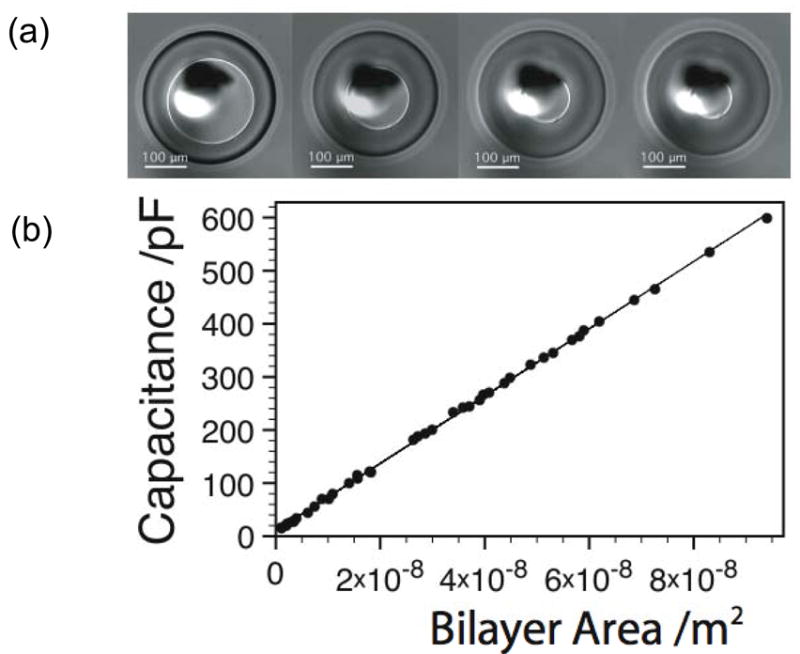
Measurement of specific capacitance by modulating the bilayer area of a DHB. (a) Image of a DHB showing control of the bilayer area. (b) Measured capacitance values for a DPhPC bilayer in hexadecane as a function of bilayer area.
E. Droplet networks
The creation of a single bilayer is accomplished by contacting two droplets. Therefore, we surmised that a network of droplets connected by DIBs might be formed simply by incorporating additional components [Fig. 6(a)]. This can be accomplished by hanging several droplets on electrodes [as in Fig. 2(c)]. However, arrays on surfaces are more practicable. For example, a plastic surface with a square array of micromachined dimples serves as a “mini-egg crate” into which droplets can be arranged in a network [Fig. 6(a)]. The spacing between the dimples and the diameter of the droplets (determined by the droplet volume) controls the diameter of the DIBs. To build a network, droplets are first stabilized (monolayer formation) and then introduced into the array of dimples. By rolling the droplets into the desired dimples with a pipette tip, a network is formed.
FIG. 6.
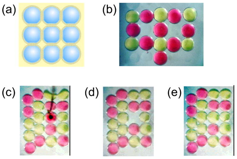
Creating and manipulating bilayer networks. (a) By using a dimpled surface as a miniature “egg-crate”, patterns of connected droplets are easily formed. (b) Light microscope image of a DIB assembly. The pink and yellow droplets are filled with dyes for visualization. The droplets are about 700 μm in diameter. Each interface between droplets is a lipid bilayer. (c) This bright-field image of twenty dye-filled droplets shows two types of ordering. The five droplets along the left edge are outside the dimple array and pack in the compact hexagonal fashion. The remaining fifteen droplets settle into the dimples and are arranged in a square lattice. The black object is an agarose-tipped electrode that has punctured a pink droplet. The hydrophilic gel acts as an anchor, and when the electrode is lifted, the droplet is excised from the network. (d) The adjacent bilayers remain intact, despite the cleavage of four bilayers as the droplet is extracted. (e) A stabilized yellow droplet is rolled into the empty dimple, demonstrating the ready reorganization of a network. This process can be repeated as often as needed. Adapted with permission from J. Am. Chem. Soc. 2007, 129, 8650–8655. Copyright 2007 Am. Chem. Soc.
The network can also be rearranged at will. After piercing a droplet with an agarose-tipped electrode, it can be lifted and extracted. Replacing extracted droplets with stabilized droplets is straightforward [Fig. 6]. Remarkably, the forces involved in rearrangement of the droplets do not damage or burst neighboring DIBs. DIB networks are stable for several days, and most likely for considerably longer.8
III. DROPLET INTERFACE BILAYERS: APPLICATIONS
A. Applications of asymmetric bilayers
Although a large number of studies on channels and pores have been carried out with symmetric bilayers, any realistic model of biological membranes must incorporate lipid asymmetry. In eukaryotic cells, anionic phospholipids and phospholipids containing primary amines are primarily found in the leaflet facing the cytoplasm, while the extracellular leaflet is enriched with choline-containing phospholipids and glycosphingolipids. Prokaryotic cells, on the other hand, have increased levels of phosphatidylethanolamine in the cytoplasmic leaflet and phosphatidylglycerol in the outer leaflet of the inner membrane.22–24 The asymmetry of biological membranes is maintained by ATP-dependent processes, suggesting that it is critical to normal cell function.25 Indeed, if cells fail to engage the mechanisms that maintain asymmetry, the chemical composition of the cell surface is changed, leading to dramatic changes in its properties. For example, the exposure of phosphatidylserine (PS) on the outer surface of a cell is often a sign of injury or apoptosis22,26 and can lead to recognition and engulfment by phagocytes.27 Cancer cells and vascular endothelial cells in tumors have also been found to present PS.28,29 There is also evidence that the differences in bilayer asymmetry between eukaryotic and prokaryotic membranes are essential to the function of antimicrobial agents which rupture bacterial membranes but leave eukaryotic cells unharmed.30
Since asymmetric bilayers are so prevalent in nature it is not surprising that many experimental methods have been developed for their study. These include planar bilayers,31,32 supported bilayers,33–35 and vesicles.36,37 The use of these approaches to investigate ion channels and pores by single-channel electrical recording is difficult owing to the inherent instability of the systems or their incompatibility with electrical recording.
The asymmetric DIB system provides a robust, electrically accessible alternative to these systems, which we have used recently to investigate changes in the behavior of outer membrane protein G [OmpG, see Table 1] that depend on the orientation of the protein in an asymmetric bilayer.16 By using the lipid-in technique, one leaflet of the bilayer was conferred with a positive charge (10 mol% dimethyldioctadecylammonium bromide (DDAB) in DPhPC), while the other leaflet was negatively charged (10 mol% 1,2-dipalmitoyl-sn-glycero-3-[phospho-rac-(1-glycerol)] (DPPG) in DPhPC). When OmpG inserted from the negative side of the asymmetric bilayer (−/+), spontaneous gating increased as compared with neutral (0/0) DIBs. Conversely, when the protein inserted from the positive side of the asymmetric bilayer (+/−), spontaneous gating decreased as compared with neutral bilayers [Fig. 7]. Combined with the observation that OmpG always inserts into DIBs with a single orientation, such that the extracellular loops remain on the side of insertion, these observations suggest that OmpG gating behavior is modulated by interactions between the extracellular loops and the lipid headgroups on the side of insertion.16,38 To confirm that the gating behavior of OmpG is not affected by the presence of the vesicles inside lipid-in DIBs, we compared spontaneous gating in symmetric DPhPC lipid-in DIBs with gating in DPhPC planar bilayers and found that they are the same.16 Preliminary studies with the chlorella virus PBCV-1 potassium channel, Kcv, have shown that it functions in a-DIBs containing charged lipids, suggesting that it will also be possible to study biomedically relevant channels such as voltage-gated potassium channels in this system.16
FIG. 7.

The behavior of OmpG in symmetric and asymmetric bilayers. (a) Current traces showing OmpG gating: Top: neutral DIB (0/0), Middle: insertion from the negative side of an asymmetric DIB (−/+), and Bottom: insertion from the positive side of an asymmetric DIB (+/−). A potential of +50 mV was applied. The buffer used was 10 mM HEPES, 200 mM KCl, pH 7.0. Protein was in the grounded droplets. (b) Comparison of mean gating probabilities (Pgating) of OmpG in a symmetric neutral planar bilayer (0/0*), symmetric neutral lipid-in DIB (0/0), and asymmetric DIBs (−/+ and +/−). Pgating is defined as the ratio of the time a pore resides in partially or fully closed states to the total recording time. Error bars represent one standard error and are based on at least ten pores. Reprinted with permission from J. Am. Chem. Soc. 2008, 130, 5878–5879. Copyright 2008 Am. Chem. Soc.
Cell membrane asymmetry is maintained by a combination of activities: (a) flip, an energy-dependent movement of phospholipids from the outer to inner leaflet; (b) flop, an energy-dependent movement of phospholipids from the inner to outer leaflet; and (c) scrambling, a Ca2+-dependent, but energy-independent, nonspecific randomization of lipids across the bilayer. Although it is established that dynamic reorientation of membrane lipids occurs both in normal physiology, to maintain asymmetry, and in times of pathologic duress, to signal cell injury, the identity and mechanisms of the proteins that promote flip-flop and their regulation remain unclear.24,39,40 Asymmetric DIB systems that model the composition of natural bilayers might be used to study the proteins that have been implicated in flip-flop mechanisms (see section IV).
B. Single-molecule fluorescence in DHBs
Single-molecule fluorescence measurements of model membranes are capable of revealing insights into the dynamics and heterogeneity of membrane processes, for example, the assembly mechanisms of membrane protein complexes.41 Single-molecule fluorescence from lipid bilayers can be achieved either in vivo,42,43 by using solid-supported bilayers,44 or with bilayers formed across an aperture44–46 or at the end of a glass pipette.47–49 Current methods are not without their drawbacks: (i) Although in vivo single-molecule experiments tell us about biomolecule behavior in a ‘real’ system, it is often difficult to interpret the data as there is no control of membrane lipid composition. (ii) Solid-supported bilayers suffer from the perturbative effects of the solid support, and the potential for incomplete bilayer formation. (iii) Unsupported bilayers formed across an aperture, or at the end of a glass pipette, do provide a means to image and/or electrically record from artificial bilayers. However, the complexity of the experimental set-up required to achieve this is in distinct contrast with the ease with which DHB can be used for the same purpose. In particular, the longevity of DHBs permits many experiments that would be very difficult to perform with bilayers formed by conventional methods.
We have studied the diffusional behavior of lipids in DHBs by using TIRF microscopy and single-particle tracking.9 The bilayer fluidity in DHBs was enhanced compared to values reported for lipid bilayers supported on glass and was similar to fluidities observed in unsupported lipid bilayers.44 The fraction of the lipids interacting with the underlying surface in DHBs was negligible, again in clear contrast to glass-supported lipid bilayers.44 Complete bilayer coverage and unhindered mobility are particularly important for the investigation of multi-component lipid systems, e.g. studies of microdomain formation, where it is important to discriminate between diffusional behavior due to lipid composition and, for example, behavior arising from incomplete bilayer formation on a solid support.
DHBs have been used to study the pore-forming toxin α-hemolysin at two stages in its assembly pathway.9 The diffusion of the water-soluble monomeric pore precursor and the lipid bilayer-embedded heptameric β-barrel pore were monitored by single-particle tracking, in separate experiments. We observed a marked difference in mobility between the two species. The high mobility of the monomeric form was consistent with a membrane-bound conformation with no significant penetration into the lipid bilayer.
C. Single-molecule fluorescence with single-channel recording
While single-channel recording experiments have provided a wealth of functional detail about many ion-channels, it is often difficult to link the information obtained to specific changes in protein structure, protein-protein interactions, or protein-substrate interactions. Single-molecule fluorescence of labelled proteins or substrates provides a means to obtain structural and dynamic information, as widely demonstrated with soluble proteins.50 Hence, simultaneous optical and electrical measurements47,51–53 have the potential to clarify aspects of channel function, such as voltage-dependent gating, that cannot be fully elucidated with the individual techniques.
Substantial effort has already been applied to the development of various in vitro lipid bilayer systems for simultaneously acquiring electrical and optical information at the single molecule level.47,54–59 These approaches all make use of conventional MM bilayers, generally incorporated into complex micro-machined devices where the geometries allow imaging during electrical measurements. While most of these systems are limited to far-field optics and epi-fluorescence techniques, in certain designs the MM bilayers are supported on agarose layers that are sufficiently thin to allow TIRF imaging.47,54,56
Based on these systems, the most advanced in vitro examples of simultaneous single-molecule experiments on bilayers to date include the observation of the fusion of nystatin-loaded fluorescent vesicles,47 the tracking of the diffusion of Cy3-labelled alamethicin channels47 and the observation of transiently dimerized dye-labelled gramicidin channels with FRET.55 However, while all these systems have demonstrated the ability to examine a wide range of channels at the single molecule level, they have yet to unambiguously demonstrate simultaneous optical and electrical measurements of the same molecules. This is in part due to the fact that the MM bilayers used in these approaches are normally substantially larger than the microscope’s field of view, and therefore electrical events can occur in regions of the bilayer that are not being imaged. Further, in some configurations, there is a build up of fluorescence near the annulus, which can obscure the few active channels.55 The limited success of these platforms can also be attributed to the inherent limitations of MM bilayers; in particular, the difficulties in creating reproducible bilayers, the low success rate of bilayer formation, and their fragile and short-lived nature.
DHB-based systems on the other hand potentially provide a robust platform for carrying out simultaneous optical and electrical measurements at the single-molecule level [Fig. 7]. Although they are yet to be implemented together, the components necessary for such experiments have already been demonstrated: single-channel recording of a wide range of proteins has been shown in a range of water-in-oil systems,2,3,8–10 and single-molecule TIRF measurements have been demonstrated with DHBs.9
D. Gel scanning
As we have seen, the various water-in-oil bilayer approaches possess several significant characteristics that are not shared by conventional MM bilayer systems, and which might be exploited in new applications. One unusual application is the use of DHBs to scan the surfaces of hydrogels to electrically detect proteins and analytes within the gels [Figure 8(a)].10 The method makes use of the ability to translate a droplet across the surface of a hydrogel immersed in a lipid/oil solution. A droplet is placed on an electrode attached to an xyz micromanipulator and used to form a DHB. The droplet (and hence the DHB) can be moved without breakage across the surface with the manipulator or the DHB can be cleaved at will and reformed at a new location. Importantly, cleaving the bilayer removes the inserted channels from the droplet, allowing fresh channels to insert when the bilayer is reformed. In this manner, a small bilayer approximately 200 μm in diameter can be scanned across the surface of a large gel many centimeters in size, opening up two distinct implementations: first, to examine the properties of channel blockers located within a gel and, second, to detect regions of a gel containing membrane proteins.
FIG. 8.
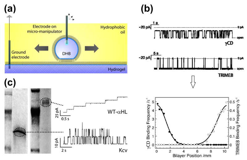
Scanning gels with DHBs. (a) Schematic showing a droplet, which forms a DHB that can be translated across the surface of the hydrogel by means of an inserted Ag/AgCl electrode attached to a micromanipulator. (b) DHBs containing αHL pores, inserted from the droplet side, can be used to detect blockers within gels. The electrical recordings (top) reflect the clearly distinguishable binding characteristics of two cyclodextrins, γ-cyclodextrin (γCD, 68% block) and heptakis(2,3,6-tri-O-methyl)-β-cyclodextrin (TRIMEB, 95% block), with wild-type αHL (−50 mV, 1 M KCl, 10 mM Na phosphate, pH 7.0). The graph (bottom) shows the relative binding frequencies of the two cyclodextrins as a function of distance for a linear DHB scan across the gel. The two species, which were doped into the gel approximately 10 mm apart, are clearly resolved. (c) Channels and pores insert into DHBs during scans of SDS-polyacrylamide gels. The proteins only insert when the DHB is positioned over the electrophoretically separated bands. The figure shows the recordings (right) from DHB scans of gels (left) containing wild-type αHL (WT-αHL) and Kcv. Adapted with permission from J. Am. Chem. Soc. 2007, 129, 16042–16047. Copyright 2007 Am. Chem. Soc.
In the first implementation, α-hemolysin in the bilayer of a DHB was used as a molecular sensor to scan for blockers within a polyacrylamide gel. The α–hemolysin was inserted into the bilayer from the droplet side of the DHB, and importantly, the transmembrane pore remained in the bilayer when the DHB was translated across the surface of the gel. In this manner, single pores within the bilayer were used to detect electrically the transient binding events associated with blockers present in different regions of the gel. For example, wild-type αHL was used to discriminate two different cyclodextrin molecules that were doped into two regions approximately 10 mm apart in a 2% polyacrylamide gel [Fig. 8(b)]. Cyclodextrins act as non-covalent blockers that lodge inside the β barrel of αHL.60,61
In the second implementation, protein-free droplets were used to scan polyacrylamide gels to detect a range of membrane channels and pores [Fig. 8(c)], including α-hemolysin, the viral potassium channel Kcv62 and outer membrane porins from E. coli. DHB gel scanning can directly detect these proteins in both native and SDS-polyacrylamide gels after electrophoretic separation [Fig. 8(c)]. The proteins only insert when DHBs are positioned over the protein bands, and once inserted the channels and pores can be characterized by single-channel recording in the conventional manner. Cleaving the DHB removes inserted membrane proteins and allows fresh proteins to insert when the bilayer is reformed. In this way, a single DHB can be used to scan multiple types of channels and pores in a single gel. After electrophoretic separation, the conditions in a gel can be altered through dialysis, and droplets containing different buffers and ligands can be used to investigate target proteins under a wide range of conditions. The important advantage of characterizing channels directly in the separation gel is that it avoids the extraction and often difficult reconstitution steps required for single-channel recording in conventional bilayers.
Another major advantage of the approach is the high sensitivity. For example, low levels of endogenous porins could be detected when scanning gels containing E. coli cell extracts. The sensitivity precludes the need for over-expression, and opens up the possibility of proteomic experiments in which two-dimensional gels of cellular extracts are scanned for the discovery and characterization of new channels. However, this is contingent upon finding electrophoretic conditions that do not denature the proteins or subsequently inhibit insertion.
E. Rapid screening
The human genome encodes 20,000 to 25,000 proteins, which are elaborated into a vast collection of splice variants and post-translationally modified forms. These proteins present a huge number of targets for screening for biological function and against agents including pharmaceuticals and environmental toxins.63,64 Many of these protein targets are soluble and therefore they can be screened with convenient and powerful approaches that are capable of examining thousands or even millions of proteins a day. For example, gene products with enzymatic activity can often be examined in high-throughput plate-reader assays by using fluorogenic substrates, while libraries of polypeptide ligands or antibodies can be screened by phage display.
Unfortunately, membrane proteins, which comprise ~25% of the proteome,65 are not amenable to such treatments. They are often difficult to express and purify, and for assay purposes they must be incorporated into lipid bilayers or at least solubilized in detergents. The analysis of channels and pores is especially demanding in this regard, but they comprise abundant important targets, notably the ligand- and voltage-gated ion channels. It is estimated that ~400 channels are encoded in the human genome, of which ~70 alone are K+ channels.66 These proteins are drug targets for numerous conditions, notably various cardiac problems and neurological diseases. They can also underlie the malignant side effects of drugs as diverse as antibiotics and antihistamines. Humans carrying mutations in these genes can be victims of so-called “channelopathies”,67 conditions that include cardiac arrhythmias and diabetes, or present atypical adverse reactions to a variety of drugs. Identifying and understanding these mutations is an important aspect of personalized medicine.
Often, ion channels are screened by examining one cell at a time by using patch clamp recording, which requires a skilled operator. Various attempts have been made to increase the throughput of ion channel screening.68 For example, patch clamp recording has been automated with hundreds of samples examined in parallel69 or ion channel activity has been measured in a multiwell system by monitoring membrane potential with voltage-sensitive fluorescent probes.70 An ideal approach would be cheap, informative, highly parallel and reproducible. The new approaches are fairly cheap and reasonably parallel. However, they are not especially informative or reproducible. These problems arise from the nature of ensemble assays. For example, for patch clamp recording, it is often necessary to over-express the target protein in a cell line and there is significant cell-to-cell variation.69 Further, the assays don’t provide much more than IC50 values.
Single-channel recording provides additional information, such as the association and dissociation rate constants for channel blockers. In addition, single-channel recording in planar lipid bilayers provides a uniform environment for the target protein. However, like patch-clamp recording, planar bilayer recording can be tediously slow. Recently, several improvements have been made. For example, by touching the bilayer with a mechanical probe carrying a target protein (or pushing a probe into the bilayer), a single copy of the protein can be quickly inserted.14 Importantly, the target protein can be directly transferred from a bacterial colony that is over-expressing it.15 In addition, planar bilayers containing a single active pore have been stabilized and stored after polymer encapsulation.71 Despite these improvements, the large volume of bilayer chambers (usually 100 μL or more) is a major disadvantage where expensive reagents are used, which is where DIBs come into play.
The potential utility of DIBs for rapid screening was demonstrated in an experiment in which a single droplet formed from a solution containing a protein pore was coupled with one droplet after another, each of the latter containing a different blocker [Fig. 9(a)]. When a droplet containing the α-hemolysin pore was allowed to dock with a droplet containing no blocker, individual insertions of pores into the bilayer were observed. When a blocker was present, individual blockades were observed superimposed upon the insertion events. When the protein-containing droplet was brought back to the empty droplet only pore insertions but no blockades were observed, showing that blockers were not carried over from one droplet to another. The droplets used in these experiments had a volume of 200 nL, but they could be made even smaller.
FIG. 9.

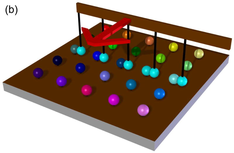

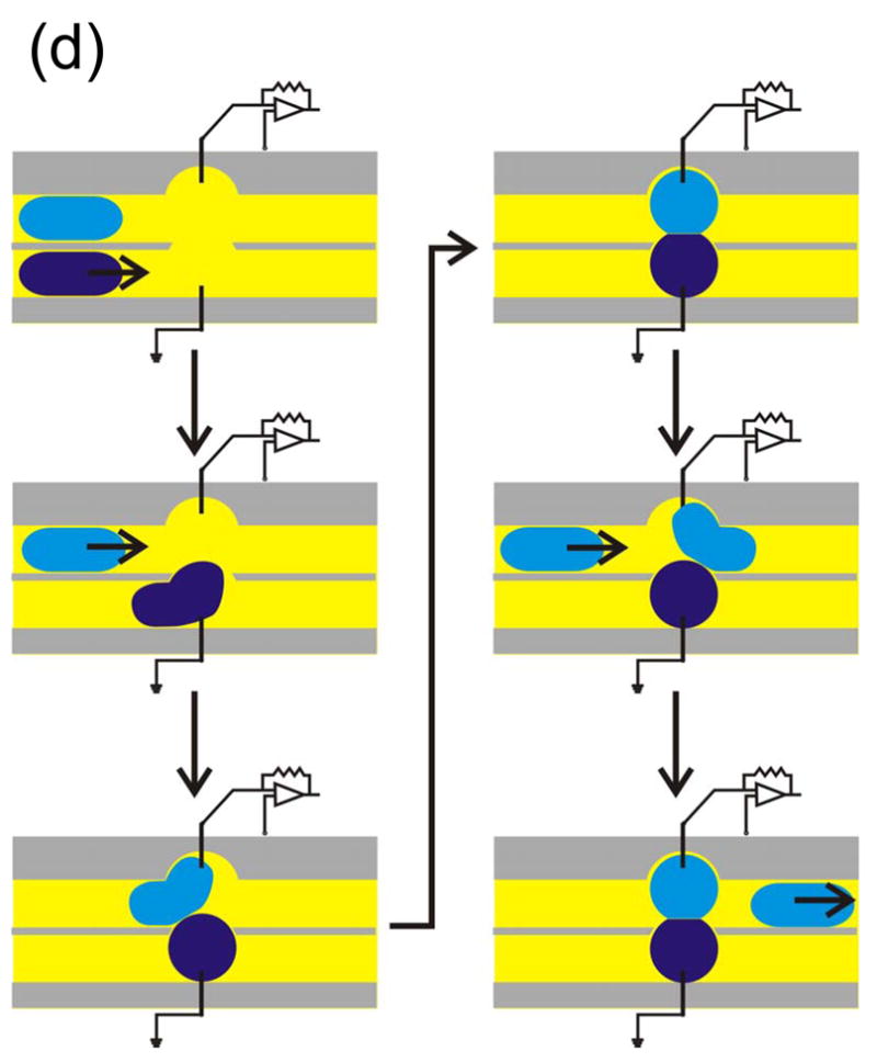
Rapid screening with DIBs. (a) Proof of principle experiment demonstrating the screening of pore blockers. A droplet containing wild-type αHL heptamers was placed on a movable electrode, while a second branched electrode was common to three analyte droplets. The first analyte droplet contained only buffer: 10 mM MOPS, 1 M KCl, pH 7.0. The second droplet contained 50 μM βCD and the third 50 μM heptakis(2,3,6-tri-O-methyl)-β-cyclodextrin (TRIMEB), in the same buffer. The αHL droplet was connected to the first analyte droplet. Pore insertions were manifested as stepwise increases in ionic current at −50 mV. The αHL droplet was then disconnected from the first droplet and moved to the second. The binding of βCD to the pores is visible as transient current blockades superimposed on the current steps caused by pore insertion. The αHL droplet was then connected to the third droplet. TRIMEB caused a larger current block than βCD, with different kinetics. Finally, the αHL droplet was reconnected to the first droplet and no binding events were observed. Reprinted with permission from J. Am. Chem. Soc. 2007, 129, 8650–8655. Copyright 2007 Am. Chem. Soc. (b) Hypothetical device for rapid screening of droplets versus droplets using the “snap-on/snap-off” process demonstrated on a smaller scale in (a). (c) A second hypothetical device in which a collection of ion channels (in an array of droplets) is screened with a collection of drugs presented as an array in a hydrated support. (d) A third hypothetical screening device in which DIBs are formed and broken in rapid succession in a microfluidic device.
As this and other experiments show, the droplets are extremely robust and it might be possible to build devices in which they are used in the “snap-on/snap-off” manner illustrated in the single droplet experiment [Fig. 9(b)]. By using such a device, all 70 human K+ channels, for example, could be screened against a variety of blockers, each encapsulated in a different droplet. We have also shown that droplets contacting planar monolayers on hydrated supports, such as agarose, form bilayers.9,10 Therefore, a collection of ion channels (in an array of droplets) could be screened with a drug, such as a blocker, present in the hydrated support [Fig. 9(c)]. Since droplets can be moved over the support surface,10 various concentrations of the drug or a variety of drugs might be tested in a single operation. Instead of an array, DIBs might be formed in a microfluidic device. Aqueous droplets are readily made in this way72,73 and droplets containing protein might be connected with droplets containing test compounds in the manner of a production line [Fig. 9(d)]. Many production lines could be run in parallel.
F. Electrical behavior of droplet interface bilayer networks
Droplets in a DIB network can act as artificial “protocells” that communicate through bilayer-incorporated proteins. Artificial protocells have been designed to perform biological functions ranging from gene transcription74,75 and protein synthesis76 to energy production and storage.77,78 Functional networks assembled from such protocells show promise as a platform for studying membrane-based phenomena in biological systems. For example, it may be possible to design a DIB network to mimic electrically propagating systems such as the sinoatrial node of the heart. The ion channels in each DIB and the biomolecules in each droplet would be manipulated to simulate both normal and pathological physiology. We have set the development of biologically relevant DIB networks on firmer ground by demonstrating an approach with which to model and simulate the electrical properties of such systems.7
When a pore-blocking molecule binds or dissociates from a pore in a single membrane system, the current change occurs instantaneously because the voltage across the bilayer is clamped at a constant value. All current blockade events have the same magnitude and shape. For comparison, we built a DIB network (“O-U”) containing transmembrane pores and reversible pore-blocking molecules [Fig. 10(a)]. Since this system has more than one bilayer, when a pore-blocking molecule binds or dissociates from a single pore, the overall network current does not change to its new steady-state value instantaneously because the fixed applied voltage is gradually redistributed among the bilayers in the network. Furthermore, even though the binding and dissociation of a blocking molecule is always the same physical interaction with a pore, the effect on the network current depends on several factors, including the bilayer areas, and the number of pores in each bilayer, and their orientation. For example, in the O-U network, two distinct types of blocking events are observed depending on whether a blocking molecule in the pink droplet binds with a pore in the left bilayer or right bilayer [Fig. 10(b)].
FIG. 10.

“O-U” DIB network. (a) A twenty-six droplet DIB network in the form of “O-U” (Oxford University). Each 200 nL droplet contains 120 ng/mL αHL heptamer in buffer (10 mM MOPS, 1 M KCl, pH 7.0) except the pink droplet in the middle, which contains 55 ng/mL αHL heptamer, 23 μM TRIMEB, and a small amount of tetramethylrhodamine (pink) in buffer. Pores became incorporated into the bilayers at each droplet interface. Two Ag/AgCl electrodes connected to micromanipulators were inserted into the droplets on the bottom left and top right corners of the network and wired to a patch-clamp amplifier to enable electrical recording. Removal and insertion of these electrodes into other droplets is straightforward. (b) Current trace with an applied potential of −50 mV. Blocking events are observed that differ from the typical “square-waves” seen with individual lipid bilayers. Adapted with permission from J. Am. Chem. Soc. 2007, 129, 11854–11865. Copyright 2007 Am. Chem. Soc.
To gain further insights into the electrical behavior of DIB networks, we focussed on the simplest possible system: a three-droplet, two-DIB network [Fig. 11] that generates the same types of phenomena observed in the O-U network. The elements of a DIB network can be considered as components of an electrical circuit: the incorporated pores and blocking molecules function as resistors, while the bilayers serve as capacitors [Fig. 11(d)]. We validated this electrical modeling approach for DIB networks by demonstrating agreement among experimental measurements, theoretical analysis, and electrical circuit simulation [Fig. 11(c)].7 Large networks can often be treated as modular arrangements of simpler systems. As networks become more complex, simulations will be critical for predicting and understanding network behavior.
FIG. 11.

Comparison of a DIB network with equivalent circuit. (a) Single DIB system in which Droplet L contains 1.7 ng/mL αHL heptamer and droplet R contains 10 μM TRIMEB, both dissolved in buffer (10 mM MOPS, 1 M KCl, pH 7.0). The potential is applied to Droplet R and Droplet L is grounded. The pores insert with the cap domain in Droplet L and the β barrel in the bilayer. An experimental current trace is shown arising from a single αHL pore in a DIB at an applied potential of −50 mV. The arrow indicates the insertion of the pore. One non-covalent blocking event by TRIMEB is shown. Notice that blocking events in single bilayers exhibit square steps. Levels 1 and 2 indicate the states in which the pore is blocked by TRIMEB and the unblocked pore, respectively. (b) Simple double DIB network in which Droplet L contains buffer (10 mM MOPS, 1 M KCl, pH 7.0), M contains 1.7 ng/mL αHL heptamer in buffer, and R contains 10 μM TRIMEB in buffer. The potential is applied to Droplet R and Droplet L is grounded. The current is measured from Droplet R to Droplet L. The pores insert into the two membranes with opposing orientations as shown. (c) Experimental current trace of a transient TRIMEB blocking event when there is a single pore in each bilayer of the arrangement shown in (b). Notice the curvature in the trace. The applied potential is −50 mV. The overlaid plot of current versus time was derived by applying Kirchhoff’s laws to the equivalent circuit, which is depicted in panel (d). The following parameter values are assigned: RA = 0.9 GΩ, R = 1 GΩ, (open), R* = 9 GΩ, CA = 350 pF, and CB = 500 pF. (d) Schematic of the equivalent circuit for analysis of blocking events in a double DIB system with any bilayer-pore configuration. We assume that only one pore in bilayer B is blocked at a time. CA is the capacitance and RA is the net resistance of bilayer A (all pores in bilayer A combined). CB is the capacitance of bilayer B, is the net resistance of bilayer B excluding one pore (all pores in bilayer B combined except one that interacts with the blocker), R represents a single pore in bilayer B that interacts with the blocker, and R* represents the state when the blocker has interacted with pore R. Opening the switch in the circuit simulates the binding of the blocker to the pore, and closing the switch simulates the dissociation of the blocker from the pore. If there is only one pore in bilayer B, we set to an infinite resistance. Adapted with permission from J. Am. Chem. Soc. 2007, 129, 11854–11865. Copyright 2007 Am. Chem. Soc.
G. Functional Networks
The high stability of DIB networks is enabling the creation of functional systems. By incorporating membrane proteins such as ion channels, pores and pumps, networks of bilayers might be engineered to simulate biological processes. We have made initial steps in this area. For example, a “bio-battery” based on an electrochemical gradient was designed, employing three coupled droplets [Fig. 12(a)].8 The left droplet contained an αHL mutant, N123R, that was engineered to be moderately anion selective. The salt solutions in the left and middle droplets were 100 mM and 1 M in NaCl, respectively. The right droplet contained the M113F/K147N αHL homoheptamer and β-cyclodextrin (βCD) in 1 M NaCl. The left and right droplets were connected to a patch-clamp amplifier with Ag/AgCl electrodes and the middle droplet was hung from a movable wire. By moving the middle droplet into position, bilayer formation was accomplished at both interfaces. After pore insertion at both interfaces, the N123R pores allowed a higher flux of Cl− relative to Na+ ions from the middle droplet into the left droplet, which provided a potential of approximately +30 mV (estimated by using the GHK equation) at the right DIB. This voltage powered the system, which in this case was employed to observe binding interactions79 between the M113F/K147N αHL pores and βCD [Fig. 12(b)].
FIG. 12.

A battery powered by a concentration gradient. (a) Three droplets in a row form two DIBs. The right two droplets contain a 1 M NaCl solution, while the left droplet contains a 100 mM NaCl solution. The N123R αHL mutant in the left DIB is anion selective, which allows a greater chloride ion flux from the middle to left droplet relative to the sodium ion flux. (b) The self-generated voltage powers the flow of ions through the system, thereby enabling the investigation of binding events at the right DIB. Here, we observe βCD binding reversibly to the M113F/K147N αHL mutant. Adapted with permission from J. Am. Chem. Soc. 2007, 129, 8650–8655. Copyright 2007 Am. Chem. Soc.
Besides autonomous power generation, DIB networks can be used to build biomimetic sensors. For example, we constructed a light-sensing network based on the light-driven proton pump, bacteriorhodopsin (BR).8 Three droplets containing BR suspension were arranged on electrodes around a central droplet [Fig. 13(a, b)]. A fifth droplet containing αHL was arranged on an opposing electrode, and pore insertions into the final DIB completed the electrical circuit. When a 1 mW green pen laser illuminated the network, a spike of electrical current was observed. Each BR transports one proton across the membrane per photon of light absorbed, thereby generating a current [Fig. 13(c)]. The magnitude of the currents observed suggests that thousands of copies of BR are working in each membrane. Here, the DIB array effectively “sees” its environment by exploiting molecular machinery borrowed from an organism. Looked at from a different viewpoint, the use of BR and light provides a means to power a droplet network with an external source of energy. By contrast, the biobattery based on an ion gradient [Fig. 12] is internally powered and will eventually run down.
FIG. 13.

Mimicking a sensory system with a droplet network. (a) Three droplets containing the light-driven proton pump bacteriorhodopsin, solubilized in 0.001% dodecylmaltoside, surround a central droplet containing buffer. On the left, an αHL-containing droplet completes the electrical circuit. Upon irradiation with a green laser, thousands of bacteriorhodopsin proteins in each DIB move protons (positive charge) across their respective bilayers. (b) This is manifested as a spike in the ionic current flowing through the system, which stops when the laser is turned off. This simple network “sees” light, and generates a signal that can be interpreted (in this case by a computer). Reprinted with permission from J. Am. Chem. Soc. 2007, 129, 8650–8655. Copyright 2007 Am. Chem. Soc.
H. Protein expression within droplets
In much of our recent work with αHL and conventional planar bilayers, we have used αHL subunits generated by coupled in vitro transcription and translation (IVTT) with a commercial E. coli T7 S30 extract.80 The polypeptides are oligomerized on rabbit erythrocyte membranes and purified by gel electrophoresis before incorporation into bilayers or droplets (see section II.B) for single-channel recording. Presumably, the oligomers contain a low concentration of SDS from the gel, which facilitates incorporation. Since aqueous droplets can serve as biological nanoreactors,81,82 we have explored the possibility of running the IVTT reaction directly inside one droplet of a two-droplet bilayer system. αHL was used for preliminary experiments [Fig. 14(a)]. Although IVTT is generally carried out at concentrations of salt less than 50 mM, we added 250 mM KCl to the IVTT mix to aid the current recordings, with satisfactory results. After adding the final IVTT component, a droplet was formed and incubated in the oil bath for 5 minutes before joining with a second droplet. Immediately after bilayer formation, observation of the ionic current showed the formation of αHL pores in the bilayer and block by γ-cyclodextrin (γCD) [Fig. 14(c)]. To determine the lag time for the production of complete αHL polypeptide chains in the IVTT system, we examined the rate of synthesis by SDS-PAGE [Fig. 14(a)]. No full-length αHL polypeptides were seen before two minutes, but a faint band appeared at 5 minutes, which is consistent with the slow rate of protein synthesis in cell-free extracts, here at a non-optimal salt concentration.83 Therefore, it can be concluded that the αHL activity observed in our experiments [Fig. 14(a)] must be derived from protein produced within the droplet. Because insertion began as soon as the droplets were brought together, the presence of a bilayer during the synthesis of polypeptide chains is not a requirement in this case. But this is not surprising because αHL monomers are water-soluble and able to assemble spontaneously on planar bilayers. It is possible that the presence of a bilayer during synthesis will be required for membrane proteins that aggregate or precipitate in the absence of membranes, and further exploration of this area is required.
FIG. 14.

In vitro transcription and translation (IVTT) to form a functional αHL pore inside a droplet. (a) The cis droplet contained the IVTT mix, DNA (400 ng/μL) and DPhPC (1.4 mM) vesicles in 10 mM HEPES buffer, 250 mM KCl at pH 7.0. The trans droplet contained DPhPC (1.4 mM) vesicles in the same buffer with γCD (10 μM). The IVTT mix includes all the components necessary for transcription and translation. The oil was a mixture of hexadecane and decane in a 10:1 ratio. (b) Visualization of an SDS-polyacrylamide gel by autoradiography showing protein expression after different time intervals. (c) Current trace showing the insertion of a WT αHL pore (arrow) followed by blockades (60% of current) representing γCD binding.
IVTT within droplets bypasses many of the time consuming steps of protein expression and purification, and will therefore facilitate analysis of the properties of the channels and pores at the single-molecule level, including the rapid screening of collections of ion channels for drug discovery (see section III.E). If the efficiency of insertion is sufficient, so that a single plasmid per droplet suffices to yield measurable activity, it will be possible to screen libraries of mutant channels.81,82 For example, the structural basis of the susceptibility of a channel to blockers would be better understood if random mutagenesis could be used to define the residues that strengthen binding.
I. Double bilayers: towards the study of direct cell-cell communication
Important protein complexes that span two membranes are found in nature and include the secretory apparatus of gram negative bacteria84 and the nuclear pores of eukaryotes85,86. Another example is the gap junction, which spans two bilayer membranes separated by a uniform gap of 2 to 5 nm at the junction between two cells.87 Each gap junction is formed through the linkage of a hemichannel (a hexamer of connexins) presented by each cell to yield the communicating pair. Gap junctions are involved in a wide range of biological processes requiring cell-cell communication including cardiac development, hematopoiesis, tissue regeneration, fertility, and immune system function.88–90 Mutations in connexin genes are responsible for many diseases including cochlear deafness, cardiac arrhythmias, and cataracts.
Understanding the properties and mechanisms of gap junction-mediated electrical and chemical signaling under normal and pathological conditions remains an important challenge. However, the intercellular nature of gap junction channels makes them difficult to study and requires analytical techniques different from those applied to channels that span a single bilayer. The reconstitution of junctional channels in an artificial double-bilayer platform would be extremely valuable for both characterization by single-channel recording and the determination of molecular transfer rates. Nevertheless, it is a challenge to bring two bilayers close enough (<5 nm) to enable hemichannels to dock and form gap junctions. There have been at least two previous attempts to create such a system, but they found limited success.91,92
We have demonstrated an extension of DIB technology that enables the formation of two closely juxtaposed bilayers with the potential to study dual-membrane spanning proteins. The double-bilayer platform incorporated two aqueous droplets or agarose spheres each brought into contact with one of the two sides of a water film in a 10 mM DPhPC/hexadecane solution [Fig. 15(a)]. A stabilization period preceded assembly of the system to allow the droplets and each side of the water film to become coated with lipid monolayers. The experimental chamber was designed such that an aqueous reservoir lies underneath the larger oil-lipid bath and is connected by a small slot [Fig. 15(b)]. A piece of 1.5-mm silver wire was pounded flat at one end and a large aperture (d = 0.8 mm) was drilled on the flattened surface (the “wand”). After treatment with NaClO, the wand was attached to a dipping mechanism that enabled the wand to slide through the slot into the aqueous reservoir [Fig. 15(c)]. When the wand was brought back through the slot into the oil-lipid bath a thin water film remained across the aperture. Two additional Ag/AgCl electrodes within either an aqueous droplet or an agarose sphere were submerged in the oil-lipid bath and connected to micromanipulators. After sufficient stabilization, the droplets (or spheres) were carefully brought into contact with the water film forming a double bilayer. The water film is remarkably stable, lasting for hours to days. Moreover, each bilayer can be separated and reformed independently and repeatedly.
FIG. 15.

Formation of a double bilayer. (a) A schematic cross-sectional enlargement of a water film stretched across the aperture of a Ag/AgCl wand, illustrating the formation of a double bilayer between two opposed aqueous droplets and an aqueous film. The two gray blocks at the top and bottom represent the surface of the wand. The droplets can be replaced with agarose spheres if greater mechanical rigidity is desired. (b) Schematic cross-section of the chamber used to form double bilayers. A dipping mechanism moves the Ag/AgCl wand between the upper oil-lipid bath and the lower aqueous reservoir. The aperture of the wand acquires a thin water film. (c) Dipping mechanism of the double bilayer platform. The wand is pressed down through the slot and into the aqueous chamber and held with a screw. To bring the water film-coated wand back into the oil-lipid bath, the screw is loosened and springs provide a restoring force. (d) A double bilayer was formed with 5 μM TRIMEB in one 2.5% (w/v) agarose sphere and 5 μM γCD in the other, and a water film containing 2 ng/mL WT αHL. The current trace exhibits both TRIMEB (larger amplitude) and γCD (lower amplitude) blocks at an applied potential of +50 mV.
To verify the presence of two bilayers, we put αHL heptamers into the water reservoir (water film) and used two different non-covalent blockers, γCD and heptakis(2,3,6-tri-O-methyl)-β-cyclodextrin (TRIMEB)), one in each droplet (or sphere) [Fig. 15(a)]. We observed both types of blocking events and the water film remained intact, which demonstrated that there were two bilayers [Fig. 15(d)]. As the two agarose spheres press into the water film from either side, the water moves radially away from the double bilayer region. Although we have not yet quantified the bilayer separation, we were able to bring the two agarose spheres so close to each other that they physically deflected without rupturing the water film and double bilayer.
IV. THE FUTURE
This review has already touched upon several areas involving DIBs that are likely to be further developed. For example, asymmetric DIB systems have far-reaching potential and, for instance, might be used to study the proteins that have been implicated in lipid flip-flop mechanisms by making use of radiolabeled lipids or fluorescence assays with a confocal microscope. Asymmetric DIBs are remarkable in that their constituent leaflets can be separated, which will allow accurate measurements of lipid transfer at well-defined time-points. a-DIBs withstand mechanical stress and might also be useful in investigations of mechanosensitive channels. For example, the lipid and mechano-gated K+ channels TREK and TRAAK have been studied by using patch clamp techniques. Channel activity was shown to depend on bilayer curvature by changing the pressure applied to an inside-out patch, and on the presence of anionic amphipaths or neutral conical lipids.93 The chemical composition and asymmetry of a lipid bilayer affect its mechanical properties and, conversely, applied forces can alter the lipid distribution.94 By manipulating a DHB over a curved surface, it will be possible to determine whether forced curvature causes rearrangement of the lipid distribution of the bilayer. The implications for channel gating could then be investigated by electrical recording.
In addition, DIBs have the potential to enable precise measurements of the properties of bilayers, including their mechanical and electrical properties, and the fine points of lipid diffusion. The use of DIBs will also enable sophisticated single-molecule fluorescence experiments, using purified membrane and cytoskeleton components, which will impact areas such as cell signaling. The realization of true simultaneous electrical and fluorescence measurement of individual channels and pores in a defined environment will bring about a better understanding of phenomena including the voltage-gating of ion channels and the transport of macromolecules through protein pores. Full implementation of the double-bilayer system will permit the exploration of several medically relevant ion channel and transport systems, which have so far proved inaccessible to full electrical analysis. Better methods for the rapid screening of ion channels are required. For example, in drug development and medical diagnosis there is a huge demand for knowledge about the properties of intentional and unintentional channel blockers. DIBs appear to offer entry into this area, especially if features such as in-droplet protein expression and microfluidic droplet manipulation can be incorporated into high-throughput devices.
For these efforts to be successful, several technical issues must be addressed. For example, we must develop consistently successful approaches for getting fully assembled channels and pores into lipid bilayers. Means for transferring materials into and out of droplets such as microinjection or droplet fusion are also needed, as are ways to prevent the leakage of small molecules from them. Better means than impaled wires are needed to move, connect and disconnect droplets. Microfluidic approaches are a strong possibility, and they might also be used to generate droplets. Faster monolayer formation on newly generated droplets will be crucial for the rapid operation of microfluidic systems. Optical tweezers could be used for the manipulation of smaller droplets. It may be possible to increase the complexity of DIBs so that they more closely resemble biological membranes: for example, by patterning the supporting substrate of a DHB to mimic the cytoskeleton, or by incorporating cytoskeletal elements into a DHB substrate. By using such artificial cell membranes, with which the composition of the bathing solution can be altered during the course of an experiment, single-molecule fluorescence techniques might be used to monitor complex biological processes in an environment that closely mimics the natural system.
DIBs might also be applied to more futuristic endeavors, such as aspects of synthetic biology. For example: can we build miniature machines from droplets? While relatively stiff components such as proteins95 and DNA96 are emerging as components for nanomachines, microscale machines that mimic tissues or organisms might be developed from “soft” droplet networks, which can be perceived as collections of communicating protocells. An autonomous device that would, for example, be capable of delivering a drug to a specific tissue will require several attributes.95 It should be able to sense, compute and transmit signals, internally at least. The device should be able to utilize stored or transmitted energy, by for example converting it to motion. It should also be able to take up substances and alter them, e.g. convert a prodrug to a short-lived drug that is then secreted and used on the spot. The beginnings of several of these attributes can be found in this review, while others should be quite readily implemented. Because droplets live in oil, a capsule that will allow survival in an aqueous environment must be devised. The entire device might be stabilized by polymerizing the capsule. DIB micromachines as conceived here would be unable to replicate, thereby avoiding one of the most contentious issues in synthetic biology.97
Supplementary Material
Acknowledgments
H.B. is the holder of a Royal Society-Wolfson Research Merit Award. W.L.H. is an American Rhodes Scholar. M.I.W. is a Royal Society University Research Fellow. This work was supported by grants from the MRC, BBSRC, EPSRC, NIH, the Life Sciences Interface Doctoral Training Centre at the University of Oxford and Nikon Instruments U.K. as part of the NOMIC partnership.
Abbreviations
- αHL
staphylococcal α-hemolysin
- a-DIB
DIB with an asymmetric lipid bilayer
- BR
bacteriorhodopsin
- CMC
critical micelle concentration
- CD
cyclodextrin
- DDAB
dimethyldioctadecylammonium bromide
- DDM
n-dodecyl-β-maltoside
- DHB
DIB formed at a droplet-hydrogel interface
- DIB
droplet interface bilayer
- DOPC
L-α-dioleoyl phosphatidylcholine
- DOPE
L-α-dioleoyl phosphatidylethanolamine
- DOPG
L-α-dioleoyl phosphatidylglycerol
- DPhPC
diphytanoyl-sn-glycerol-3-phosphocholine
- DPPG
dipalmitoyl-sn-glycero-3-[phospho-rac-(1-glycerol)]
- EDTA
ethylenediamine tetraacetic acid
- FRET
fluorescence resonance energy transfer
- HEPES
N-(2-hydroxyethyl)piperazine-N′-(2-ethanesulfonic acid)
- IVTT
in vitro transcription and translation
- Kcv
a potassium channel from chlorella virus PBCV-1
- KcsA
a potassium channel from Streptomyces lividans
- MM
Montal-Mueller
- MOPS
3-(N-morpholino)-propanesulfonic acid
- OG
n-octyl-®-D-glucopyranoside
- OmpG
outer membrane protein G from E. coli, a porin
- PS
phosphatidylserine
- rRBCM
rabbit red blood cell membranes
- S30
an extract from E. coli containing, inter alia, ribosomes
- SDS
sodium dodecyl sulfate
- SDS-PAGE
sodium dodecyl sulfate-polyacrylamide gel electrophoresis
- TIRF
total internal reflection fluorescence [microscopy]
- TRIMEB
heptakis(2,3,6-tri-O-methyl)-β-cyclodextrin
References
- 1.Tsofina LM, Liberman EA, Babakov AV. Nature. 1966;212:681–683. [Google Scholar]
- 2.Funakoshi K, Suzuki H, Takeuchi S. Anal Chem. 2006;78:8169–8174. doi: 10.1021/ac0613479. [DOI] [PubMed] [Google Scholar]
- 3.Malmstadt N, Nash MA, Purnell RF, Schmidt JJ. Nano Lett. 2006;6:1961–1965. doi: 10.1021/nl0611034. [DOI] [PubMed] [Google Scholar]
- 4.Montal M, Mueller P. Proc Natl Acad Sci USA. 1972;69:3561–3566. doi: 10.1073/pnas.69.12.3561. [DOI] [PMC free article] [PubMed] [Google Scholar]
- 5.Miller C, editor. Ion channel reconstitution. Plenum; New York: 1986. [Google Scholar]
- 6.Mueller P, Rudin DO, Tien HT, Wescott WC. Nature. 1962;194:979–980. doi: 10.1038/194979a0. [DOI] [PubMed] [Google Scholar]
- 7.Hwang WL, Holden MA, White S, Bayley H. J Am Chem Soc. 2007;129:11854–11864. doi: 10.1021/ja074071a. [DOI] [PubMed] [Google Scholar]
- 8.Holden MA, Needham D, Bayley H. J Am Chem Soc. 2007;129:8650–8655. doi: 10.1021/ja072292a. [DOI] [PubMed] [Google Scholar]
- 9.Thompson JR, Heron AJ, Santoso Y, Wallace MI. Nano Lett. 2007;7:3875–8. doi: 10.1021/nl071943y. [DOI] [PubMed] [Google Scholar]
- 10.Heron AJ, Thompson JR, Mason AE, Wallace MI. J Am Chem Soc. 2007;129:16042–7. doi: 10.1021/ja075715h. [DOI] [PubMed] [Google Scholar]
- 11.Malmstadt N, Jeon TJ, Schmidt JJ. Adv Mater. 2008;20:84–90. [Google Scholar]
- 12.White SH. Biophys J. 1972;12:432–45. doi: 10.1016/S0006-3495(72)86095-8. [DOI] [PMC free article] [PubMed] [Google Scholar]
- 13.Horn C, Steinem C. Biophys J. 2005;89:1046–54. doi: 10.1529/biophysj.105.059550. [DOI] [PMC free article] [PubMed] [Google Scholar]
- 14.Holden MA, Bayley H. J Am Chem Soc. 2005;127:6502–6503. doi: 10.1021/ja042470p. [DOI] [PubMed] [Google Scholar]
- 15.Holden MA, Jayasinghe L, Daltrop O, Mason A, Bayley H. Nature Chemical Biology. 2006;2:314–318. doi: 10.1038/nchembio793. [DOI] [PubMed] [Google Scholar]
- 16.Hwang WL, Chen M, Cronin B, Holden MA, Bayley H. J Am Chem Soc. 2008;130:5878–5879. doi: 10.1021/ja802089s. [DOI] [PubMed] [Google Scholar]
- 17.Mitev DJ, Ivanova T, Vassilieff CS. Colloids and Surfaces B: Biointerfaces. 2002;24:185–192. [Google Scholar]
- 18.Capitani D, Segre AL, Dreher F, Walde P, Luisi PL. J Phys Chem. 1996;100:15211–15217. [Google Scholar]
- 19.White SH, Thompson TE. Biochim Biophys Acta. 1973;323:7–22. doi: 10.1016/0005-2736(73)90428-8. [DOI] [PubMed] [Google Scholar]
- 20.White SH. Biochim Biophys Acta. 1973;323:343–50. doi: 10.1016/0005-2736(73)90180-6. [DOI] [PubMed] [Google Scholar]
- 21.White SH. Ann N Y Acad Sci. 1977;303:243–65. [PubMed] [Google Scholar]
- 22.Balasubramanian K, Schroit AJ. Annu Rev Physiol. 2003;65:701–34. doi: 10.1146/annurev.physiol.65.092101.142459. [DOI] [PubMed] [Google Scholar]
- 23.Devaux PF, Morris R. Traffic. 2004;5:241–6. doi: 10.1111/j.1600-0854.2004.0170.x. [DOI] [PubMed] [Google Scholar]
- 24.Pomorski T, Menon AK. Cell Mol Life Sci. 2006;63:2908–21. doi: 10.1007/s00018-006-6167-7. [DOI] [PMC free article] [PubMed] [Google Scholar]
- 25.Pomorski T, Hrafnsdottir S, Devaux PF, van Meer G. Semin Cell Dev Biol. 2001;12:139–48. doi: 10.1006/scdb.2000.0231. [DOI] [PubMed] [Google Scholar]
- 26.Fadok VA, Voelker DR, Campbell PA, Cohen JJ, Bratton DL, Henson PM. J Immunol. 1992;148:2207–2216. [PubMed] [Google Scholar]
- 27.Schroit AJ, Madsen JW, Tanaka Y. J Biol Chem. 1985;260:5131–8. [PubMed] [Google Scholar]
- 28.Utsugi T, Schroit AJ, Connor J, Bucana CD, Fidler IJ. Cancer Res. 1991;51:3062–6. [PubMed] [Google Scholar]
- 29.Zwaal RF, Comfurius P, Bevers EM. Cell Mol Life Sci. 2005;62:971–88. doi: 10.1007/s00018-005-4527-3. [DOI] [PubMed] [Google Scholar]
- 30.Sato H, Feix JB. Biochim Biophys Acta. 2006;1758:1245–56. doi: 10.1016/j.bbamem.2006.02.021. [DOI] [PubMed] [Google Scholar]
- 31.Krasilnikov OV, Capistrano MFP, Yuldasheva LN, Nogueira RA. J Membrane Biol. 1997;156:157–172. doi: 10.1007/s002329900198. [DOI] [PubMed] [Google Scholar]
- 32.Hagge SO, de Cock H, Gutsmann T, Beckers F, Seydel U, Wiese A. J Biol Chem. 2002;277:34247–53. doi: 10.1074/jbc.M201950200. [DOI] [PubMed] [Google Scholar]
- 33.Katagiri K, Hashizume M, Kikuchi J, Taketani Y, Murakami M. Colloids Surf B Biointerfaces. 2004;38:149–53. doi: 10.1016/j.colsurfb.2004.05.019. [DOI] [PubMed] [Google Scholar]
- 34.Crane JM, Kiessling V, Tamm LK. Langmuir. 2005;21:1377–88. doi: 10.1021/la047654w. [DOI] [PubMed] [Google Scholar]
- 35.Wacklin HP, Thomas RK. Langmuir. 2007;23:7644–51. doi: 10.1021/la063476q. [DOI] [PubMed] [Google Scholar]
- 36.McIntyre JC, Sleight RG. Biochemistry. 1991;30:11819–27. doi: 10.1021/bi00115a012. [DOI] [PubMed] [Google Scholar]
- 37.Pautot S, Frisken BJ, Weitz DA. Proc Natl Acad Sci U S A. 2003;100:10718–21. doi: 10.1073/pnas.1931005100. [DOI] [PMC free article] [PubMed] [Google Scholar]
- 38.Chen M, Khalid S, Sansom MSP, Bayley H. Proc Natl Acad Sci U S A. 2008;105:6272–6277. doi: 10.1073/pnas.0711561105. [DOI] [PMC free article] [PubMed] [Google Scholar]
- 39.Kol MA, de Kroon AI, Killian JA, de Kruijff B. Biochemistry. 2004;43:2673–81. doi: 10.1021/bi036200f. [DOI] [PubMed] [Google Scholar]
- 40.Daleke DL. J Biol Chem. 2007;282:821–5. doi: 10.1074/jbc.R600035200. [DOI] [PubMed] [Google Scholar]
- 41.Bayley H, Jayasinghe L, Wallace M. Nat Struct Mol Biol. 2005;12:385–6. doi: 10.1038/nsmb0505-385. [DOI] [PubMed] [Google Scholar]
- 42.Mashanov GI, Tacon D, Peckham M, Molloy JE. J Biol Chem. 2004;279:15274–80. doi: 10.1074/jbc.M312140200. [DOI] [PubMed] [Google Scholar]
- 43.Lommerse PH, Blab GA, Cognet L, Harms GS, Snaar-Jagalska BE, Spaink HP, Schmidt T. Biophys J. 2004;86:609–16. doi: 10.1016/S0006-3495(04)74139-9. [DOI] [PMC free article] [PubMed] [Google Scholar]
- 44.Schutz GJ, Schindler H, Schmidt T. Biophys J. 1997;73:1073–80. doi: 10.1016/S0006-3495(97)78139-6. [DOI] [PMC free article] [PubMed] [Google Scholar]
- 45.Ide T, Takeuchi Y, Aoki T, Yanagida T. Jpn J Physiol. 2002;52:429–34. doi: 10.2170/jjphysiol.52.429. [DOI] [PubMed] [Google Scholar]
- 46.Ichikawa T, Aoki T, Takeuchi Y, Yanagida T, Ide T. Langmuir. 2006;22:6302–7. doi: 10.1021/la0535025. [DOI] [PubMed] [Google Scholar]
- 47.Ide T, Takeuchi S, Yanagida T. Single Molecules. 2002;3:33–42. [Google Scholar]
- 48.Harms GS, Orr G, Montal M, Thrall BD, Colson SD, Lu HP. Biophys J. 2003;85:1826–38. doi: 10.1016/S0006-3495(03)74611-6. [DOI] [PMC free article] [PubMed] [Google Scholar]
- 49.Harms G, Orr G, Lu HP. Appl Phys Lett. 2004;84:1792–1794. [Google Scholar]
- 50.Cornish PV, Ha T. ACS Chem Biol. 2007;2:53–61. doi: 10.1021/cb600342a. [DOI] [PubMed] [Google Scholar]
- 51.Macdonald AG, Wraight PC. Prog Biophys Mol Biol. 1995;63:1–29. doi: 10.1016/0079-6107(94)00007-v. [DOI] [PubMed] [Google Scholar]
- 52.Helluin O, Dugast JY, Molle G, Mackie AR, Ladha S, Duclohier H. Biochim Biophys Acta. 1997;1330:284–92. doi: 10.1016/s0005-2736(97)00139-9. [DOI] [PubMed] [Google Scholar]
- 53.Ishii Y, Yanagida T. Single Molecules. 2000;1:5–16. [Google Scholar]
- 54.Ide T, Yanagida T. Biochem Biophys Res Commun. 1999;265:595–599. doi: 10.1006/bbrc.1999.1720. [DOI] [PubMed] [Google Scholar]
- 55.Borisenko V, Lougheed T, Hesse J, Fureder-Kitzmuller E, Fertig N, Behrends JC, Woolley GA. Biophys J. 2003;84:612–622. doi: 10.1016/S0006-3495(03)74881-4. [DOI] [PMC free article] [PubMed] [Google Scholar]
- 56.Ide T, Ichikawa T. Biosens Bioelectron. 2005;21:672–7. doi: 10.1016/j.bios.2004.12.018. [DOI] [PubMed] [Google Scholar]
- 57.Suzuki H, Tabata KV, Noji H, Takeuchi S. Langmuir. 2006;22:1937–42. doi: 10.1021/la052534p. [DOI] [PubMed] [Google Scholar]
- 58.Suzuki H, Tabata KV, Noji H, Takeuchi S. Biosens Bioelectron. 2007;22:1111–5. doi: 10.1016/j.bios.2006.04.013. [DOI] [PubMed] [Google Scholar]
- 59.Sandison ME, Zagnoni M, Morgan H. Langmuir. 2007;23:8277–84. doi: 10.1021/la7007528. [DOI] [PubMed] [Google Scholar]
- 60.Gu LQ, Braha O, Conlan S, Cheley S, Bayley H. Nature. 1999;398:686–690. doi: 10.1038/19491. [DOI] [PubMed] [Google Scholar]
- 61.Gu LQ, Bayley H. Biophys J. 2000;79:1967–1975. doi: 10.1016/S0006-3495(00)76445-9. [DOI] [PMC free article] [PubMed] [Google Scholar]
- 62.Gazzarrini S, Severino M, Lombardi M, Morandi M, DiFrancesco D, Van Etten JL, Thiel G, Moroni A. FEBS Lett. 2003;552:12–6. doi: 10.1016/s0014-5793(03)00777-4. [DOI] [PubMed] [Google Scholar]
- 63.Nicholson RL, Welch M, Ladlow M, Spring DR. ACS Chem Biol. 2007;2:24–30. doi: 10.1021/cb600321j. [DOI] [PubMed] [Google Scholar]
- 64.Inglese J, Johnson RL, Simeonov A, Xia M, Zheng W, Austin CP, Auld DS. Nat Chem Biol. 2007;3:466–79. doi: 10.1038/nchembio.2007.17. [DOI] [PubMed] [Google Scholar]
- 65.Lehnert U, Xia Y, Royce TE, Goh CS, Liu Y, Senes A, Yu H, Zhang ZL, Engelman DM, Gerstein M. Q Rev Biophys. 2004;37:121–46. doi: 10.1017/s003358350400397x. [DOI] [PubMed] [Google Scholar]
- 66.Gutman GA, Chandy KG, Grissmer S, Lazdunski M, McKinnon D, Pardo LA, Robertson GA, Rudy B, Sanguinetti MC, Stuhmer W, Wang X. Pharmacol Rev. 2005;57:473–508. doi: 10.1124/pr.57.4.10. [DOI] [PubMed] [Google Scholar]
- 67.Ashcroft FM. Nature. 2006;440:440–7. doi: 10.1038/nature04707. [DOI] [PubMed] [Google Scholar]
- 68.Zheng W, Spencer RH, Kiss L. Assay Drug Dev Technol. 2004;2:543–52. doi: 10.1089/adt.2004.2.543. [DOI] [PubMed] [Google Scholar]
- 69.Dale TJ, Townsend C, Hollands EC, Trezise DJ. Mol Biosyst. 2007;3:714–22. doi: 10.1039/b706152h. [DOI] [PubMed] [Google Scholar]
- 70.Huang CJ, Harootunian A, Maher MP, Quan C, Raj CD, McCormack K, Numann R, Negulescu PA, Gonzalez JE. Nat Biotechnol. 2006;24:439–46. doi: 10.1038/nbt1194. [DOI] [PubMed] [Google Scholar]
- 71.Kang X-f, Cheley S, Rice-Ficht AC, Bayley H. J Am Chem Soc. 2007;129:4701–4705. doi: 10.1021/ja068654g. [DOI] [PubMed] [Google Scholar]
- 72.Link DR, Anna SL, Weitz DA, Stone HA. Phys Rev Lett. 2004;92:054503. doi: 10.1103/PhysRevLett.92.054503. [DOI] [PubMed] [Google Scholar]
- 73.Garstecki P, Fuerstman MJ, Stone HA, Whitesides GM. Lab Chip. 2006;6:437–46. doi: 10.1039/b510841a. [DOI] [PubMed] [Google Scholar]
- 74.Fischer A, Franco A, Oberholzer T. Chembiochem. 2002;3:409–17. doi: 10.1002/1439-7633(20020503)3:5<409::AID-CBIC409>3.0.CO;2-P. [DOI] [PubMed] [Google Scholar]
- 75.Noireaux V, Libchaber A. Proc Natl Acad Sci USA. 2004;101:17669–17674. doi: 10.1073/pnas.0408236101. [DOI] [PMC free article] [PubMed] [Google Scholar]
- 76.Pietrini AV, Luisi PL. Chem biochem. 2004;5:1055–62. doi: 10.1002/cbic.200400014. [DOI] [PubMed] [Google Scholar]
- 77.Bennett IM, Farfano HMV, Bogani F, Primak A, Liddell PA, Otero L, Sereno L, Silber JJ, Moore AL, Moore TA, Gust D. Nature. 2002;420:398–401. doi: 10.1038/nature01209. [DOI] [PubMed] [Google Scholar]
- 78.Bhosale S, Sisson AL, Talukdar P, Furstenberg A, Banerji N, Vauthey E, Bollot G, Mareda J, Roger C, Wurthner F, Sakai N, Matile S. Science. 2006;313:84–6. doi: 10.1126/science.1126524. [DOI] [PubMed] [Google Scholar]
- 79.Kang X, Gu LQ, Cheley S, Bayley H. Angew Chem Int Ed Engl. 2005;44:1495–1499. doi: 10.1002/anie.200461885. [DOI] [PubMed] [Google Scholar]
- 80.Walker BJ, Krishnasastry M, Zorn L, Kasianowicz JJ, Bayley H. J Biol Chem. 1992;267:10902–10909. [PubMed] [Google Scholar]
- 81.Tawfik DS, Griffiths AD. Nature Biotechnology. 1998;16:652–656. doi: 10.1038/nbt0798-652. [DOI] [PubMed] [Google Scholar]
- 82.Aharoni A, Griffiths AD, Tawfik DS. Curr Opin Chem Biol. 2005;9:210–6. doi: 10.1016/j.cbpa.2005.02.002. [DOI] [PubMed] [Google Scholar]
- 83.Underwood KA, Swartz JR, Puglisi JD. Biotechnol Bioeng. 2005;91:425–35. doi: 10.1002/bit.20529. [DOI] [PubMed] [Google Scholar]
- 84.Piddock LJ. Nat Rev Microbiol. 2006;4:629–36. doi: 10.1038/nrmicro1464. [DOI] [PubMed] [Google Scholar]
- 85.Alber F, Dokudovskaya S, Veenhoff LM, Zhang W, Kipper J, Devos D, Suprapto A, Karni-Schmidt O, Williams R, Chait BT, Rout MP, Sali A. Nature. 2007;450:683–94. doi: 10.1038/nature06404. [DOI] [PubMed] [Google Scholar]
- 86.Alber F, Dokudovskaya S, Veenhoff LM, Zhang W, Kipper J, Devos D, Suprapto A, Karni-Schmidt O, Williams R, Chait BT, Sali A, Rout MP. Nature. 2007;450:695–701. doi: 10.1038/nature06405. [DOI] [PubMed] [Google Scholar]
- 87.Evans WH, Martin PE. Mol Membr Biol. 2002;19:121–36. doi: 10.1080/09687680210139839. [DOI] [PubMed] [Google Scholar]
- 88.Traub O, Druge PM, Willecke K. Proc Natl Acad Sci U S A. 1983;80:755–9. doi: 10.1073/pnas.80.3.755. [DOI] [PMC free article] [PubMed] [Google Scholar]
- 89.Harris AL. Quarterly Reviews of Biophysics. 2001;34:325–472. doi: 10.1017/s0033583501003705. [DOI] [PubMed] [Google Scholar]
- 90.Kidder GM, Mhawi AA. Reproduction. 2002;123:613–20. doi: 10.1530/rep.0.1230613. [DOI] [PubMed] [Google Scholar]
- 91.Fisher LR, Parker NS, Haydon DA. Faraday Disc Chem Soc. 1986;81:249–256. [Google Scholar]
- 92.Brewer GJ. In: Biophysics of gap junction channels. Peracchia C, editor. CRC Press; Boca Raton: 1991. pp. 301–316. [Google Scholar]
- 93.Patel AJ, Lazdunski M, Honore E. Curr Opin Cell Biol. 2001;13:422–8. doi: 10.1016/s0955-0674(00)00231-3. [DOI] [PubMed] [Google Scholar]
- 94.Janmey PA, Kinnunen PK. Trends Cell Biol. 2006;16:538–46. doi: 10.1016/j.tcb.2006.08.009. [DOI] [PubMed] [Google Scholar]
- 95.Astier Y, Bayley H, Howorka S. Curr Opin Chem Biol. 2005;9:576–84. doi: 10.1016/j.cbpa.2005.10.012. [DOI] [PubMed] [Google Scholar]
- 96.Seeman NC. Mol Biotechnol. 2007;37:246–57. doi: 10.1007/s12033-007-0059-4. [DOI] [PMC free article] [PubMed] [Google Scholar]
- 97.Lartigue C, Glass JI, Alperovich N, Pieper R, Parmar PP, Hutchison CA, 3rd, Smith HO, Venter JC. Science. 2007;317:632–8. doi: 10.1126/science.1144622. [DOI] [PubMed] [Google Scholar]
Associated Data
This section collects any data citations, data availability statements, or supplementary materials included in this article.