Introduction
Cranio-Maxillofacial Surgery (CMF) involves the correction of congenital and acquired conditions of the head and face. In the United States, a significant number of patients require surgery for these types of conditions. They include patients with of congenital and developmental deformities of the CMF region (17 million) 1-7, defects after tumor ablation (28,000 new patients per year)8, post-traumatic defects (200,000 per year)9, 10 and deformities of the temporomandibular joint (6000 patients per year require prosthetic and autogenous TMJ reconstruction)11, 12. The latest figures indicate that 33,000 US servicemen and women have been wounded in action in both Operation Iraqi Freedom and Operation Enduring Freedom.13 It is estimated the one fourth to one third of them suffered head and neck injuries.14
The surgical correction of CMF deformities is among the most challenging. The success of these surgeries depends not only on the technical aspects of the operation, but also, to a larger extent, on the formulation of a precise surgical plan.15-24 Over the last 50 years, there have been significant improvements in the technical aspects of surgery, i.e. rigid fixation, resorbable materials, distraction osteogenesis, minimally invasive approaches, etc. However, the planning methods have mostly remained unchanged.17, 18, 20, 24 It is clear that many of the unwanted surgical outcomes are the result of deficient planning.
The need to improve the traditional surgical planning methods has led our group to develop a 3D computer-aided surgical simulation (CASS) system to plan CMF surgery. We have utilized this system in maxillofacial surgery23, 25-27, craniofacial surgery28, trauma, distraction osteogenesis28-30 and TMJ reconstruction31. Using this system, a doctor can perform “virtual surgery” and create a 3D prediction of the patient's surgical outcomes, as if they are performing surgery in the operating room. We have documented the clinical feasibility18, 24, the accuracy32 and cost-effectiveness33 of this system. Our CASS system incorporates 3 distinctive features and innovations: 1) multiple imaging modalities are used to create an accurate model of the craniofacial skeleton; 2) special techniques are employed to orient the computerized bone model in the natural head position (NHP); and 3) Computer-Aided Design/Computer-Aided Manufacturing (CAD/CAM) techniques are used to fabricate accurate surgical splints and templates to transfer the surgical plan to the operating room. The purpose of this article is to present our CASS planning protocol.
Clinical Protocol
Step 1: Creation of a computerized composite skull model
A composite skull model simultaneously displays an accurate rendition of both the bony structures and the teeth. Although 3D CT scans have been successfully used to visualize the patient's condition, they have not successfully been used for surgical simulation because the CT does not render the teeth with the accuracy that is necessary for surgical simulation. In order to replace the inaccurate dentition in the 3D CT model, we created a composite skull model by incorporating accurate digital dental models into a 3D CT model of the face. This is done by merging 2 separate digital data sets: the digital dental models and the 3D CT. The merger of separate data sets is done by utilizing common reference points between the 2 sets. Our approach utilizes fiducial markers for this purpose. In our system, the fiducial markers are spheres that are part of a plastic facebow. The facebow is attached to an acrylic bite registration that is place in the patient and on the dental models before they are scanned (Fig.1a).
Figure 1.

Creation of the computerized composite skull model
a. Facebow with fiducial markers is attached to the bite-jig.
b. The patient is biting on the bite-jig and facebow during CT scan.
c. Three separate but correlated computer models are reconstructed: a midface model, a mandibular model and a fiducial-marker model.
d. The bite-jig and facebow is placed between the upper and lower plaster dental models during the scanning process.
e. Three separate but correlated computer models are also reconstructed: an upper digital dental model, a lower digital dental model, and a fiducial-marker model.
f. By aligning the fiducial markers, the digital dental models are incorporated into the 3D CT skull model. The computerized composite skull model is thus created. It simultaneously displays an accurate rendition of both the bony structures and the teeth.
The first step in our clinical routine is to fabricate the acrylic bite registration. The bite registration is taken using low-shrinkage methyl methacrylate (i.e. Duralay). The acrylic is first placed on a bite jig and the impression is taken on the occlusal surfaces of the upper teeth. After the acrylic has hardened, additional material is placed in the mandibular side of the jig and the mandibular bite registration is captured in centric relationship.
Once the bite registration is created, it is attached to the facebow. A CT scan of the patient's craniofacial skeleton is obtained while the patient is biting on the bite registration (Fig.1b). The CT scan is completed using the standard scanning algorithm, matrix of 512×512 at 0.625-1.25 mm slice thickness, 25cm or lesser field-of-view (FOV), 0° gantry tilt and 1:1 pitch. After segmentation, 3 separate but correlated computer models are generated: a midface model, a mandibular model and a fiducial-marker model (Fig.1c).
The digital dental models are then created by scanning the plaster dental models, the bite-jig and the facebow (Fig.1d). This can be done with a surface scanner (resolution: 0.1mm or higher) or with a micro-CT scanner (resolution: 7μm-75μm). This generates 3 separate but correlated computer models: an upper digital dental model, a lower digital dental model, and a fiducial-marker model (Fig.1e).
After the 3D CT models and the digital dental models are obtained, the teeth of the CT skull model are removed, leaving the fiducial markers in place. The upper and the lower digital dental models with their corresponding fiducial markers are imported into the CT skull model. By aligning the fiducial markers, the digital dental models are incorporated into the 3D CT skull model. The fiducial markers are then hidden. This results in a computerized composite skull model, which simultaneously displays an accurate rendition of the bones and the teeth (Fig.1f).18, 24, 34-36
Step 2: Orientation of the composite skull model in the Natural Head Position
Because many patients with CMF deformities have significant asymmetries of the upper face and skull base, common cephalometric landmarks and planes cannot be used to orient the composite skull model. The use of the Natural Heal Position (NHP) obviates the need for internal landmarks and provides a reproducible reference framework. Our laboratory has developed 2 techniques to orient the composite model to the NHP: The first one utilizes a 3D laser surface scanner and the second a digital gyroscope. In both methods, the natural head position is established using a modified Molhave method.37 The patient faces a blank wall at a distance of 2 meters in an isolated standing or sitting position. The patient is then asked to establish the NHP by flexing and extending her head and then balancing in a position of comfort while looking straight ahead without specific focus.
With the laser surface scanner method, the surface geometry of the facial soft tissues is captured while the patient is in the HNP. During the scanning the patient is sitting on a calibrated chair at the center of the scanner. The scanner creates a correctly oriented 3D image of the face. The soft tissues of the composite model are then rendered and the model is aligned to the NHP by matching its soft tissues to the scanned image (Fig 2).18, 24
Fig 2.
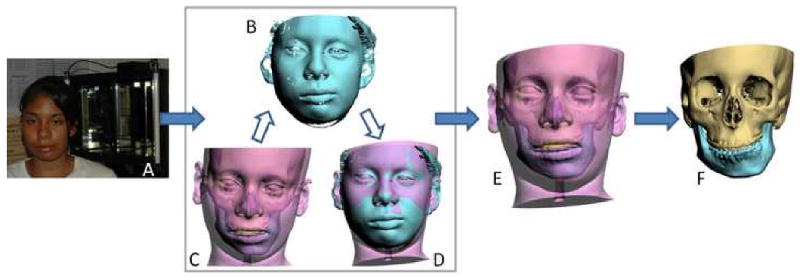
Orientation of the composite skull model to the NHP using the laser scanner method
a. The surface geometry of the facial soft tissue is captured while the patient is sitting on a calibrated chair at the center of the laser scanner
b. Captured surface geometry (scanned image) of the facial soft tissue.
c. In the computer, a soft tissues model is rendered and the composite model is “glued” to the soft tissue model.
d. The soft tissue model is aligned to the NHP by matching it to the scanned image.
e. Both soft tissue and composite skull models are thus oriented to the NHP.
f. The composite skull model is in the NHP after the soft tissue is hidden.
The second technique is the one we are currently using in our clinical practice. In this technique, a digital gyroscope is attached to the same facebow. With the patient in the NHP, the pitch, roll and yaw of the face are recorded.38-40 The recorded pitch, roll and yaw are then used to reorient the composite skull model. In the computer, a digital replica (CAD model) of the gyroscope is registered to the composite skull model (via the fiducial markers) and the 2 objects are attached to each other. Afterwards, the recorded pitch, roll and yaw are applied to the center of the gyroscope replica reorienting the composite skull model to the NHP (Fig. 3).
Fig 3.

Orientation of the composite skull model to the NHP using the digital gyroscope method
a. A digital gyroscope is attached to the bite-jig and facebow.
b. The pitch, roll and yaw of the gyroscope are recorded.
c. In the computer, a digital replica (CAD model) of the gyroscope is registered to the composite skull model (via the fiducial markers) and the 2 objects are attached to each other.
d. The recorded pitch, roll and yaw are applied to the center of the gyroscope replica reorienting the composite skull model to the NHP
e. After the composite skull is orientated to the NHP, the gyroscope replica is marked hidden.
The advantages of the gyroscope technique are cost and convenience. The gyroscope costs a hundred times less than the laser scanner, it is portable, and requires little maintenance. In addition to the methods described above, other methods may be used to record the NHP. They include the use of a 3D digitizer 41 and photographs. In the latter method, lateral and frontal photos are taken orthogonally using a camera that is calibrated to the true vertical plane (Fig 4).
Fig 4.
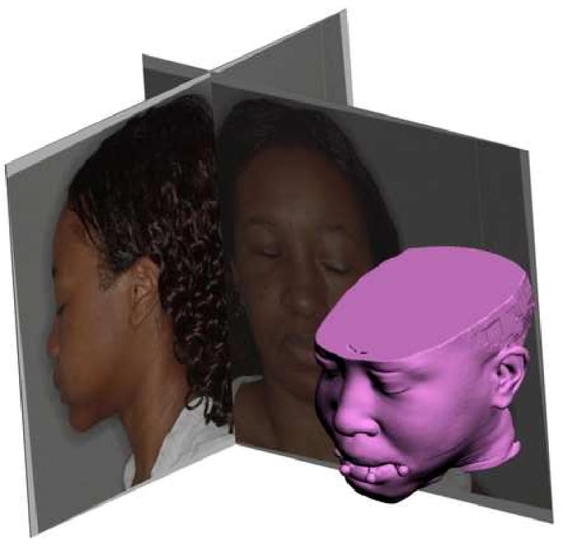
Photographic method utilizes a calibrated camera to take orthogonal lateral and frontal photos when the patient is in the NHP. The recorded NHP is then transferred to 3D composite model in the computer.
Step 3: Analysis and quantification of the deformity
In this step, the user completes a cephalometric analysis. In CASS, this can be done in 2- or 3-dimensions. To facilitate this task, a unique 3D reference system is constructed for the composite model. The reference system has its origin at soft-tissue Nasion and consists of 3 orthogonal planes: sagittal, coronal and axial. Once the composite model is positioned in the 3D reference system, the user digitizes the selected cephalometric landmarks and chooses the desire analysis. The computer automatically performs all the necessary calculations and presents the cephalometric results. In some instances, because of the difficulty interpreting some 3D data and the unavailability of the 3D normative data, we are still using a conventional 2D analysis.
To perform the 2D cephalometric analysis, a 2D cephalogram is emulated by the software using a volume rendering algorithm (i.e. ray-casting algorithm). It projects the CT voxels onto a sagittal plane (Fig. 5). Although all the cephalometric landmarks are digitized in 3-dimensions, this virtual lateral cephalogram allow us to perform a conventional 2D analysis. In this mode, we make decisions regarding anteroposterior projection, vertical position, and inclinations of the occlusal plane and mandibular plane (pitch).
Fig 5.
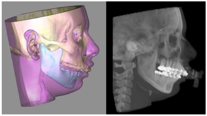
A cephalogram is emulated using volume rendering to project the CT voxels onto the sagittal plane.
One of the advantages of CASS is the ability to measure structures in 3 dimensions. In the 3D analysis, we examine anatomical structures for symmetry. To examine the symmetry of the maxilla, we have developed a method based on the work of Grayson.42-44 This method creates a triangular spline on the maxillary dentition by digitizing 3 landmarks: the maxillary dental midline, the mesiobuccal cusp of the maxillary right first molar and the mesiobuccal cusp of the maxillary left first molar (Fig 6). The software reads the x, y and z coordinates of each vertex of the triangle to automatically calculate the pitch, roll and yaw of the maxilla as well as the maxillary midline deviation. The pitch represents the maxillary occlusal plane, while the roll and yaw represent the occlusal cant and the horizontal discrepancy.
Fig 6.
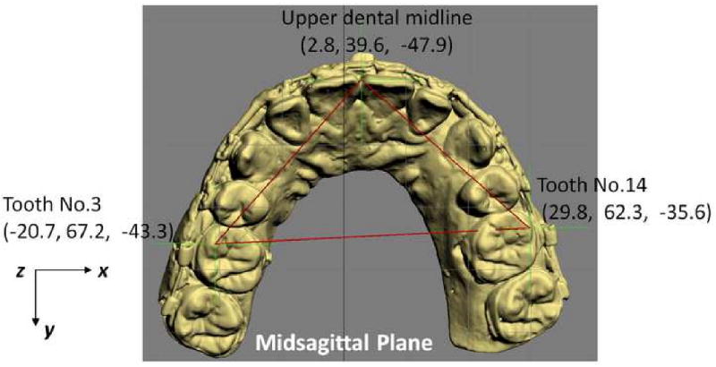
In triangle method, a triangular spline is created on the maxillary dentition by digitizing 3 landmarks: 1) the dental midline, 2) the mesiobuccal cusp of the maxillary right first molar and 3) the mesiobuccal cusp of the maxillary let first molar. The software reads the x, y and z coordinates of each vertex of the triangle to automatically calculate the pitch, roll and yaw of the maxilla as well as the maxillary midline deviation. The pitch represents the maxillary occlusal plane, while the roll and yaw represent the occlusal cant and the horizontal discrepancy.
In addition to the 2D and 3D measurements, the software is also able to perform volumetric measurements. These measurements have proven to be useful in the quantification of airway and orbital volumes (Fig 7).
Fig 7.
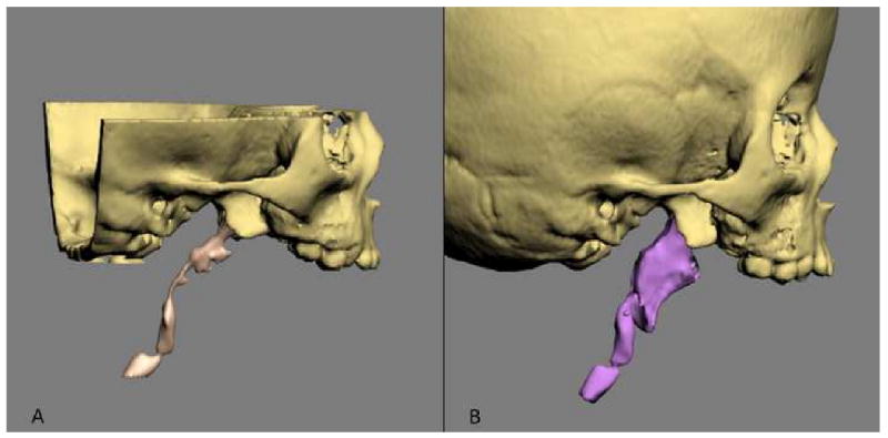
Volumetric measurements are used to measure the size of the airway and orbital volumes.
a. Airway preoperatively
b. Airway postoperatively
Step 4: Simulation of surgery in the computer
Using this system, the user can simulate any type of osteotomy, i.e., Le Fort I, sagittal split, genioplasty, etc. After the bones are osteotomized, the user can move and rotate the bony segments to the desired position. In patients requiring bimaxillary surgery, the maxilla is usually repositioned first. The triangular spline used to quantify the maxillary asymmetry is “glued” to the maxilla so that any movement of the triangle is automatically transferred to the maxilla. The software reads the x, y and z coordinates of the triangle vertices, calculates the discrepancy between the right and left, and automatically moves/rotates the triangle to symmetry (0° of roll, a 0° of yaw). Following this, the upper dental midline is corrected to the midsagittal plane. Finally, the doctor adjusts the maxillary pitch (occlusal plane inclination) to a desired angle (Fig 8). This triangular method works especially well when the dental arch itself is symmetrical. If the dental arch is asymmetrical, the doctor's intervention is required to move/rotate the maxilla to the most balanced position. After the asymmetry of the maxilla is corrected the maxilla is moved anteroposteriorly and superoinferiorly to the desired position based on the cephalometric analysis and clinical measurements.
Fig 8.
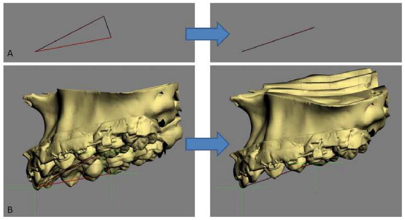
The triangular spline used to quantify the maxillary asymmetry is “glued” to the maxilla.
a. The computer reads the x, y and z coordinates of the triangle vertices and moves them to symmetry (0° of roll, a 0° of yaw).
b. The movement of the triangle is automatically transferred to the maxilla.
After the maxilla is placed in its final position, the distal segment of the mandible is moved to maximal intercuspation (MI). Unfortunately, the establishment of MI in the computer is difficult. It is almost impossible to be certain that what is seen in the computer truly represents the best possible alignment. To ensure that the digital final occlusion is at its correct MI, we scan the plaster models which are physically positioned in MI (final occlusion). The scanned models are incorporated into the composite skull model to guide the placement of the distal mandible into MI. Once the distal segment is in position, the proximal segments of the mandible are aligned. If necessary, a genioplasty is also simulated.
In some instances, the repositioning of the osteotomized segments is not sufficient to obtain facial symmetry. This is due to the fact that in many patients with facial asymmetries, the bones are not only asymmetrically displaced but also differ in size and shape from one side to the other. Therefore, it is still necessary to check for symmetry after the simulation of the jaw movements. To help with this, the software has a tool called “mirror-image”. In the mirror-image routine, one half of the face is selected, copied, flipped (mirror-imaged) and superimposed on the contralateral side (Fig 9). The software then uses Boolean operation to calculate differences between the two sides. Based on this information, the surgeon may decide to add volume (grafting), remove volume (ostectomy), or adjust the position of the segments (camouflage).
Fig 9.

In the mirror-image routine, one half of the face is
a. Selected,
b. Copied and flipped (mirror-imaged), and
c. Superimposed onto the contralateral side.
Step 5: Transfer the computerized plan to the patient
After the surgical plan is finalized, it is necessary to transfer the plan to the patient at the time of the surgery. Surgical dental splints or surgical templates can be created for this purpose. Surgical dental splints are used to reposition dentate bony segments while surgical templates are use reposition non-dentate ones. In surgeries that involved the teeth, the surgical dental splints are created by inserting a digital wafer between the maxillary and mandibular dental arches. A Boolean operation is then performed, resulting in a digital surgical splint (Fig.10a). In surgeries that do not involve the teeth, the surgical template is created to record the 3D surface geometry of the area of interest in order fit the bony segment (e.g. chin segment) onto the recipient bone (e.g. mandibular distal segment) in a unique position (Fig.10b). In surgeries that require bone grafts to achieve symmetry, the computerized mirror-imaging technique is used to mirror image the geometry from the healthy side to the affected side. The difference between the two sides is then computed, resulting in a digital template that is used at surgery to harvest and sculpt the graft. Finally, the system exports the digital splints and templates in .stl format. They are then fabricated using a rapid prototyping machine and used at the time of the surgery (Figs. 10c and 10d).
Fig 10.
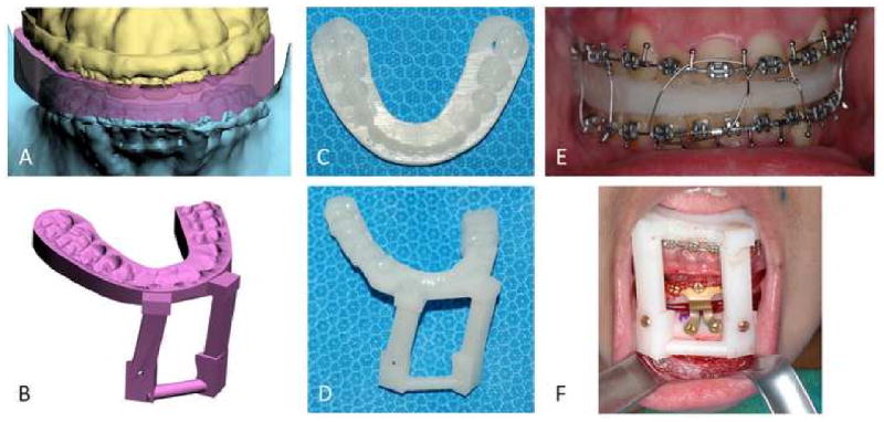
Surgical dental splints and templates are created using the authors' computer-aided designing / computer-aided manufacturing technique.
a. Digital surgical splint
b. Digital chin template
c. Physical surgical splint
d. Physical chin template
e. The use of physical surgical splint at the time of the surgery
f. The use of physical chin template at the time of the surgery
Discussion
Critical review of traditional methods used to plan CMF surgery
In CMF surgery, surgical planning involves a series of logical steps. These steps include data gathering, diagnosis and quantification of the condition, establishment of a preliminary surgical plan, surgical simulation, establishment of the final surgical plan, and transfer of the plan to the patient.
Data is gathered from a multitude of difference sources. They include the physical examination, medical photographs, plain x-rays (e.g., cephalogram, orthopantomogram), CT and mounted plaster dental models.15, 16 Each of these sources provides a portion of the whole data set that is needed for successful planning. In practice, a surgeon evaluates each one of these studies in a sequential manner and creates a complete 3D mental picture.
The next step in the planning process is the diagnosis and quantification of the deformity. In orthognathic surgery, an important part of this process is cephalometric analysis15, 45. After the surgeon has formulated the diagnosis, she develops a preliminary plan, and in many instances, alternative plans.
To test the feasibility of the preliminary plan(s), the surgeon simulates the planned surgery. In orthognathic surgery, this is done by completing prediction tracings and dental model surgery.15, 16 Prediction tracings are done by tracing the silhouette of the facial bones from a 2D cephalogram onto a piece of acetate paper. These tracings are then cut and moved to evaluate possible outcomes. This task can also be completed in the computer. Dental model surgery is then completed on plaster dental modes which have been mounted on an articulator. This is done by physically cutting the models and moving them to the desired position. In other types of surgery (e.g., trauma, pathology and reconstruction), the extent of surgical simulation is even more limited. In clinical practice, most of these surgeries are not simulated. Sometimes, doctors obtain CT-based rapid prototyping physical models (e.g., stereolithography) to simulate skeletal surgery.
After the simulation has been completed, a surgeon formulates the final surgical plan. The final step in the planning process is to transfer the surgical plan to the patient at the time of surgery. In orthognathic surgery, the surgical plan is transferred to the patient prior to surgery by using surgical splints and selected measurements. The splints are fabricated on the same plaster dental models on which the surgery was simulated. In CMF surgeries that do not involve dentition, surgeons currently do not have a method of transferring the surgical plan to the patient. Although certain measurements taken during the planning process can be used to guide surgery, most of the time the process is more of an art than a science. There have been reports on the use of surgical navigation for this purpose,31, 46-48 but this technique has not been universally adopted.
There are a number of problems associate with the traditional planning system. These include:
The various data sources utilize different coordinate systems. The physical examination and the medical photographs are taken with the patient's head oriented to the NHP. The cephalogram is oriented to the Frankfurt Horizontal (FH) plane and the articulated dental models are oriented to the axis-orbital plane.49 On an average, these planes differ from each other by about 8°.49 Currently, most surgeons are unaware of this problem and fail to account for these differences. This discrepancy alone can be responsible for a 15% difference in maxillary projection between the planned and the actual outcomes.49
Using the traditional method, surgeons are never able to visualize the whole data set in 3 dimensions.17-19, 24, 50, 51 As stated above, the surgeons have to create this picture in their minds. This creates a problem communicating with the other members of the treatment team. As it expected, it is impossible to assure that all involved have the same picture.
The cephalometric analysis is 2-dimensional. Therefore, it only measures structures in a single plane. It may be appropriate for patients with symmetrical deformities, but is inadequate for patients with asymmetric conditions.17, 22 It has been reported that 34% of patients with dentofacial deformities have asymmetric conditions.52
The orientation of the dental models mounted on an articulator is often inaccurate. The occlusal plane inclination of the dental models mounted on a semi-adjustable articulator is on an average 8° steeper.49, 53 In addition, there are design flaws in the current devices used to orient the dental models on an articulator (i.e., the facebow). A patient can easily tilt the facebow during the registration process creating an inaccurate recording of the occlusal cant (roll of the maxilla). An inaccurate initial model position will always create an inaccurate plan.53
The plaster dental models do not depict the surrounding bones. Dental model surgery is done for 2 purposes. The first is to establish the occlusion and the second is to reorient the models to assure that the bones are placed in the ideal position at surgery. Because plaster dental models do not depict the surrounding bones, the surgeon is unable to visualize the effects of model position on the facial skeleton.19, 20, 35 Therefore, the ability to obtain the ideal bone position becomes a random event.18, 20, 21
Prediction tracing and model surgery are two separate processes, which are often inaccurate and time consuming.17, 54, 55 Currently, an experienced surgeon spends 3-5 hours completing these steps.33
Some surgeons utilized CT-based rapid prototyping models to plan complex surgeries.50 The drawbacks to these rapid prototyping models are that they costly (a single model costs about $2500) and they are unable to simulate different iterations of a given plan on a single model. Once the model is cut, the cut cannot be undone. Finally, they fail to render the teeth with the precision necessary for surgical planning.17, 18, 24
The fabrication of splints is time consuming. A busy surgeon performs several of these operations per week and many patients require 2 splints. The fabrication of each splint may take an additional hour.16, 33
For surgeries that do not involve the dentition, surgeons do not have a way of transferring the surgical plan to the patient.17, 20, 22, 31
Quantification of CMF deformity in the CASS System
One of the basic steps in orthodontic or CMF surgical planning is analysis and quantification of the deformity. Traditionally, this has been done by clinical examination (direct anthropometry), cephalometry or by visually inspecting a 3D CT model. Until the recent advent of 3D imaging, craniofacial analysis had to be done in 2 dimensions. Most current anthropometric tables and cephalometric norms are 2-dimensional. Thanks to the advances in computer technology, we are now able to perform these analyses 3-dimensionally. In traditional cephalometry all structures are projected onto a single plane and bilateral landmarks are averaged. In 3D cephalometry, these landmarks exist 3-dimensionally and thus true 3D measurements can be made. However, these measurements are often difficult to interpret. It is especially true for those 3D measurements which are directly translated (expanded) from their original 2D form. A simple example is the gonial angle (Ar-Go-Me). In a 2D analysis, the change in this angle is easy to interpret. If this angle is outside the normal range, it can be said that the “bend” of mandible is abnormal. The same is not necessarily true in a 3D analysis. Anatomically, the mandibular condyles (Ar) and the gonial angles (Go) are on the lateral side of the face which are significantly separated from the sagittal plane where the Menton (Me) is located. Three-dimensionally, the gonial angle is described by a line that goes from Ar (top) to Go (bottom) and another one that goes from Go anteromedially to Me. The size of this 3D angle differs from the size of its 2D projection on the sagittal plane (Fig 11).
Fig 11.
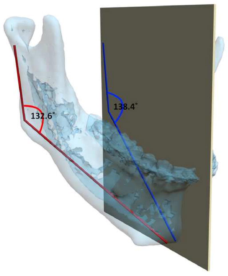
The mandibular condyles (Ar) and the gonial angles (Go) are on the lateral side of the face which are significantly separated from the midsagittal plane where the Menton (Me) is located. In this patient, the gonial angle (Ar-Go-Me) is measured as 132.6°three -dimensionally (in red), while the projection of the gonial angle on the midsagittal plane is measured as 138.4° (in blue).
For angles that theoretically exist in the sagittal plane (e.g. SNB), differences between 3D measurements and 2D measurements are relatively minor and clinically insignificant. An example of this is a patient with significant laterognathia (lateral chin deviation). In this patient point B is displaced laterally and the 3D SNB angle on this patient only differs slightly from its 2D counterpart (Fig 12).
Fig 12.
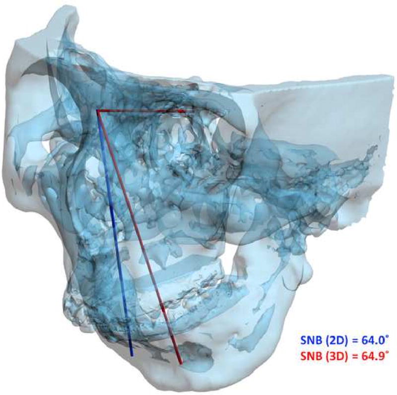
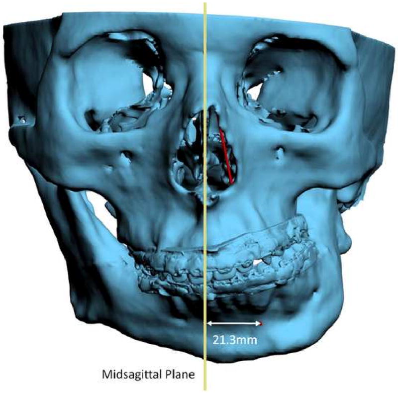
For angles that theoretically exist in the sagittal plane (e.g. SNB), differences between 3D measurements and 2D measurements are relatively minor and clinically insignificant.
a. SNB was measured as 64.9° 3-dimensionally (in red), while the projection of SNB on the midsagittal plane is measured as 64.0°(in blue).
b. Point B is 21.3mm deviated to the left.
Another problem in 3D cephalometry is the uncertainty of how angles are constructed by planes. For example, the mandibular plane angle is made by the intersection of the mandibular plane and the Frankfurt Horizontal (FH) plane. Geometrically, a plane can only be constructed by 3 points. For the mandibular plane, these points are Right Gonion, Left Gonion and Menton. For Frankfort Horizontal, the situation is more complicated. Theoretically, this plane is made by 4 points: the right and left Orbitale and the right and left Porion. Unfortunately, most of the time, these points are not in the same plane. This situation brings about new questions: how should the plane be defined? Should one of the points be ignored? Should we average 2 points, 3 points or all 4? An even bigger problem exists when the patient has an asymmetric deformity. In this scenario, the right and left landmarks are not symmetrical. Therefore, the two planes diverge from each other in all planes of space. In this situation the size of the angle between the planes varies depending on where it is measure (Fig 13).
Fig 13.
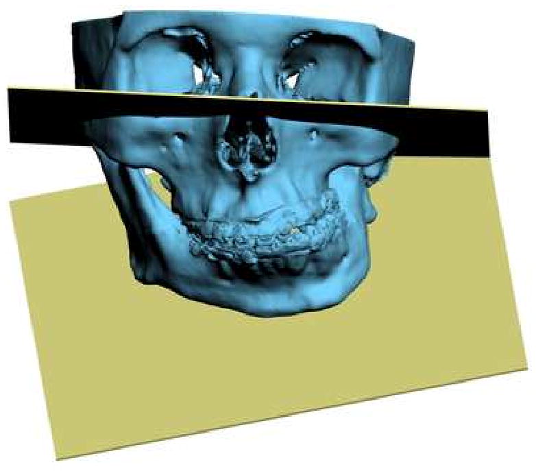
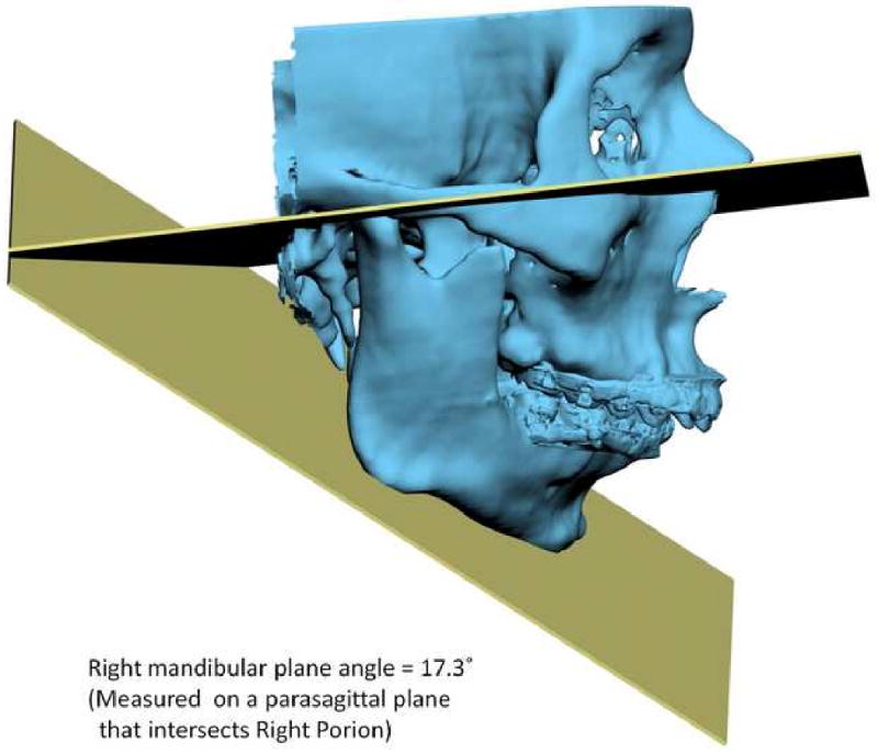
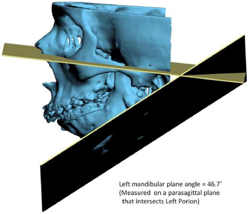
Angles made by planes are problematic in 3D cephalometry. For example, the mandibular plane angle is made by the intersection of the mandibular plane and the Frankfurt Horizontal (FH) plane. In this illustration, the mandibular plane is simply created by 3 points: Right Gonion, Left Gonion and Menton. The FH plane is more complicated. It is created by the least-square averaged 4 points: the right and left Porion and right and left Orbitale. Since the right and left landmarks are not symmetrical, the 2 planes diverge from each other in all planes of space. The size of the angle between the planes varies depending on where it is measure
a. Frontal view.
b. Right view. The right mandibular plane angle is 17.3° measured on a parasagittal plane that intersects Right Porion.
c. Left view. The left mandibular plane angle is 46.7° measured on a parasagittal plane that intersects Light Porion.
The importance of clinical examination for treatment planning of CMF deformities
As we discussed above, with this new technology we are able to create 3D models of the face that incorporate accurate renditions of the teeth, the skeleton and the soft tissues. Moreover, these models can be accurately oriented to the natural head position, an important pre-requisite for accurate planning. From this, one may infer that the value of the physical examination in the clinical decision making process will become irrelevant. In our experience, this is far from the truth. Although, these models can capture the anatomy with great detail, they are static and only present the status of the tissues at the time of image capture. Therefore, the physical examination still provides us with extremely valuable dynamic information that cannot be obtained from any other source. To illustrate this issue, we will discuss examples of pitfalls that can be encounter by relaying only on the static images.
The first example is a patient with significant mandibular laterognathia (lateral chin deviation) (Fig 14a). On assessing the alignment of the maxillary dental midline we have discovered that in some of these patients the relationship of the maxillary dental midline to the upper lip varies depending on the mediolateral position of the chin. During the physical examination, we first measure the transverse alignment of the maxillary dental midline to the middle of the upper lip while the patient is in centric relationship. In this position, the maxillary dental midline seems to be deviated opposite to the chin deviation (Fig 14b). We then measure the same alignment after we have asked the patient to move his chin to the midline simulating correction of the mandibular asymmetry. In this position, the maxillary dental midline is no longer deviated (Fig 14c). What is happening here is that the lateral displacement of the mandible is producing a deformation of the upper lip by dragging it to the side of the chin deviation. When the chin is moved to the midline, the upper lip regains its normal shape. The pitfall here is that if this dynamic deformation is not taken into account, the surgeon will “correct” a maxillary dental midline deviation that is not real. Obviously, this will create and unwanted outcome. Therefore, we recommend that the decision of correcting a maxillary midline deviation should be based on physical examination, rather than the study images.
Fig 14.
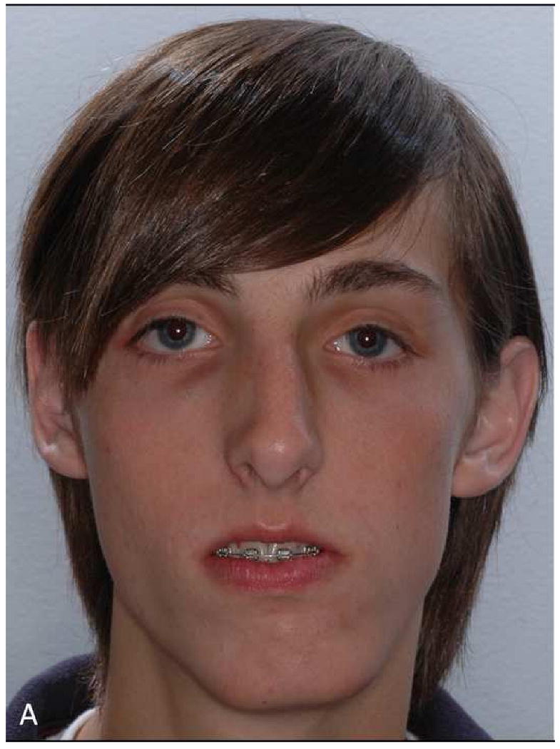
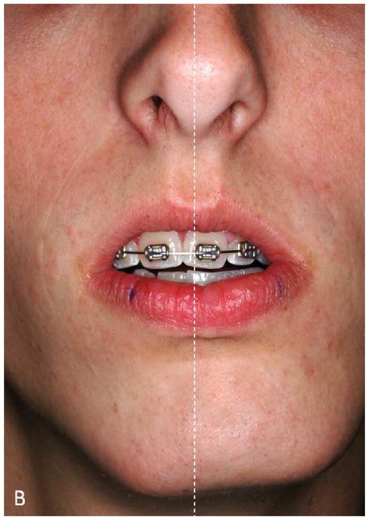
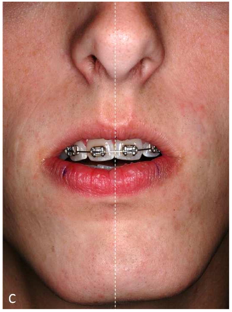
The maxillary dental midline deviation changes depending on different mandibular position.
a. A patient with significant mandibular laterognathia (lateral chin deviation).
b. The maxillary dental midline seems to be deviated opposite to the chin deviation while the patient is in centric relationship.
c. The maxillary dental midline is no longer deviated after we have asked the patient to move his chin to the midline simulating correction of the mandibular asymmetry.
Another possible pitfall on the static images relates to the assessment of the amount of maxillary incisal show. Experienced clinicians know that the amount of incisal show may vary with the patient's position. It tends to decrease when the patient changes position from supine, to sitting, and to standing (Fig 15a). If the CT scan is done on a medical scanner, it is done with the patient in the supine position. In this scenario, the amount of incisal show may seem excessive, when it is not (Fig 15b). If the scan is done of a cone-beam scanner it is usually done with the patient sitting or standing. In these scenarios, the amount of incisal shown more closely resembles the actual amount.
Fig 15.
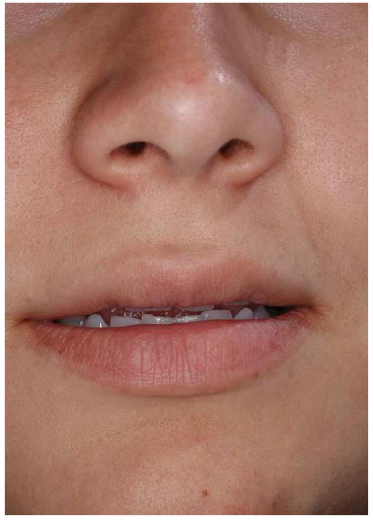
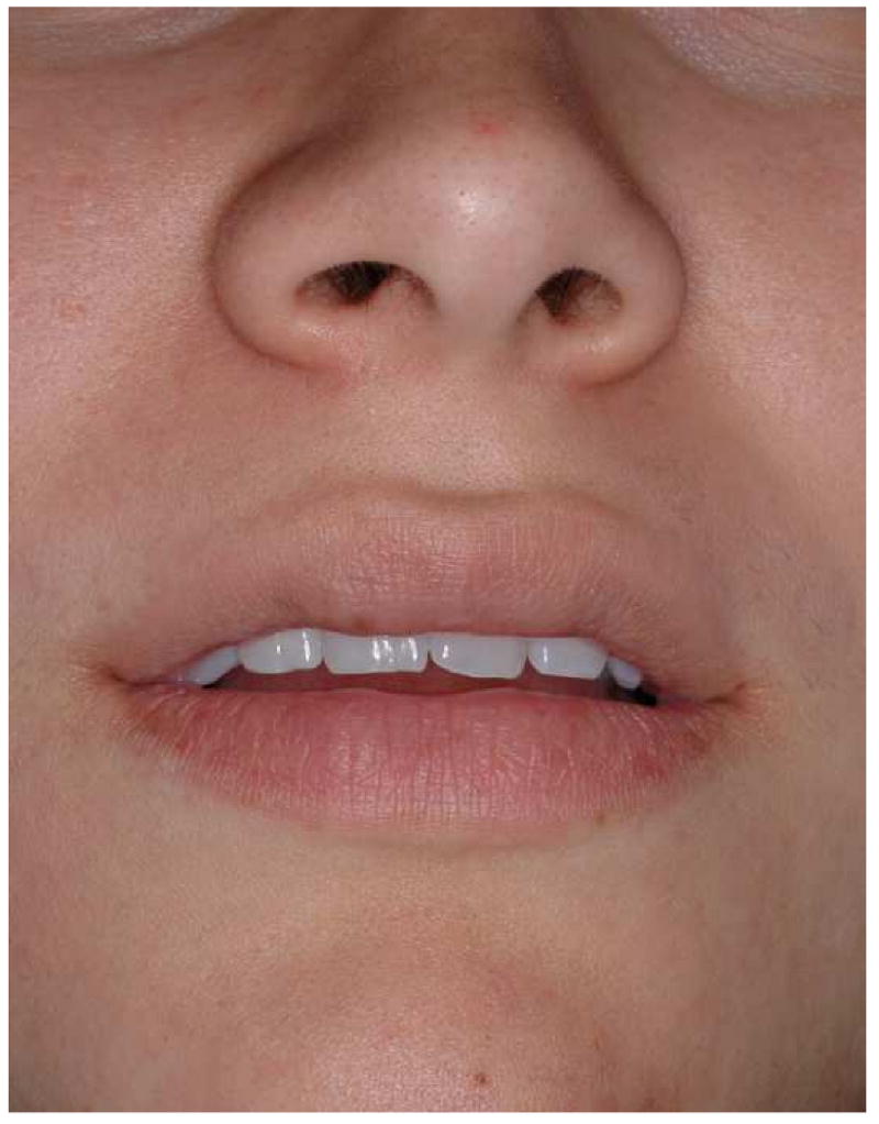
The amount of maxillary incisal show may vary with the patient's position.
a. Incisor show at standing position
b. Incisor show of the same subject at supine position
One more issue regarding the measurement of the incisal show is the uncertainty of the functional state of the lips during image acquisition. Ideally, they should be in repose. However, the functional state of the lips is questionable unless the surgeon is present during the scanning. Strained lips will produce an inaccurate determination of incisal show. Therefore, it is best to determine this parameter clinically during the physical exam rather than relying of the computer images. During the physical exam, this parameter should be measured with the patient standing in front of the surgeon. The decision on how much to change the amount of incisal show should not be based solely on the amount of show at rest. Other important issues should also be taking into account. They include the amount of gingival show during smiling, the presence of delayed passive eruption, or the presence of attrition. Finally, clinical measurements of the occlusal cant, degree of dystopia, and ear position also serve to verify that the composite skull model is correctly oriented in the 3D coordinate system.
The need for plaster dental models in the CASS system
Ideally, in the future, plaster dental models will not be necessary for CMF planning. However, at this time we are still using them to establish the final dental occlusion in maximum intercuspation (MI). Using a set of plaster dental models, an experienced operator can complete this task in a matter of seconds. The same is not true in the virtual world where the dental arches are represented by two 3D images that lack collision constraints. The computer system does not stop the images from moving through each other once the model surfaces have made contact. In addition, the operator has no tactile feedback when articulating the models. Because of these difficulties, it usually takes close to an hour to achieve the “best possible” intercuspation in the computer. More importantly, it is almost impossible to be certain that what is seen in the computer represents the true best possible intercuspation. We have not been able to rely on this computerized dental alignment to treat real patients, because even a small deviation in occlusion can cause significant clinical problems. To ensure that the digital final occlusion is at its correct MI, we scan the plaster models which are physically positioned in MI (final occlusion). The scanned models are incorporated into the composite skull model to guide the placement of the distal mandible into MI. Meanwhile, the authors are developing a method of automated digital dental articulation. Once this method is completely developed and validated, the need of plaster dental models will be eliminated.
Cost-effectiveness of using the CASS
For complex CMF surgery, the authors completed a cost-effectiveness analysis comparing the CASS method to the traditional planning method33. The results showed that CASS had lower costs in terms of surgeon time, patient time, and material costs. In the same study, the authors hypothesized that the maximum potential cost savings of CASS could be best realized when a single planning facility serves multiple surgeons, in multiple clinics, and in multiple cities. Further efficiencies can be achieved by centralized specialization where surgeon's time is replaced with the less expensive technician's time.
For routine orthognathic surgery, there have no reports comparing the CASS method to the traditional planning method. In the authors' CASS practice, the initial appointment to get records (dental impressions, bite-jig creation, clinical examination, anthropometric measurements, recording natural head position) is about 60 minutes, in which the surgeon's time is about 40 minutes. By eliminating the facebow transfer, there is a significant reduction in surgeon's time in comparison to the traditional planning method. After the patient's CT scan is completed, the preparation of the computer data, including dental model scanning, segmentation of CT images, 3D model reconstruction, composite skull model creation, landmark digitization and virtual osteotomies, are completed by a centralized service facility. Once the computer data is prepared, it is electronically transmitted to the surgeon. The surgeon only spends time on examining the cephalometric analysis results, formulating a surgical plan and testing the plan with the virtual surgical movements. While there is a learning curve in this process, once it is completed, it usually takes less than 30 minutes for a routine case, and up to an hour for an extremely complex case. After the plan is finalized, the computer data file is transmitted back to the service facility, where the computerized surgical splints and templates are generated and fabricated using a rapid prototyping machine. Currently at the service center, the entire process takes around 4 hours and costs up to $1000.56 This is slightly above the amount that is now reimbursed by insurance companies for the fabrication of an oral surgical splint (CPT code 21085). Ultimately, in this entire CASS planning process, the total surgeon's time is reduced to 70 -100 minutes per case in comparison to 9.75 hours33 in the traditional planning process.
Footnotes
Publisher's Disclaimer: This is a PDF file of an unedited manuscript that has been accepted for publication. As a service to our customers we are providing this early version of the manuscript. The manuscript will undergo copyediting, typesetting, and review of the resulting proof before it is published in its final citable form. Please note that during the production process errors may be discovered which could affect the content, and all legal disclaimers that apply to the journal pertain.
References
- 1.National Center for Health Statistics. National Hospital Discharge Survey: Annual Summary with Detailed Diagnosis and Procedure Data. Vital and Health Statistics series 13 number 151. DHHS publication No.(PHS)2001-1722. National Center for Health Statistics; Hyattsville, MD: 1999. [DOI] [PubMed] [Google Scholar]
- 2.National Institutes of Health. Management of temporomandibular disorders. National Institutes of Health Technology Assessment Conference Statement. J Am Dent Assoc. 1996;127:1595. [PubMed] [Google Scholar]
- 3.National Center for Health Statistics. Third National Health and Nutrition Examination Survey, (NHANES III, 1988-1994) National Center for Health Statistics; Hyattsville, MD: 1996. [Google Scholar]
- 4.Proffit WR, Fields HW, Jr, Moray LJ. Prevalence of malocclusion and orthodontic treatment need in the United States: estimates from the NHANES III survey. Int J Adult Orthodon Orthognath Surg. 1998;13:97. [PubMed] [Google Scholar]
- 5.Chatzis V, Pitas I. Interpolation of 3-D binary images based on morphologicalskeletonization. Medical Imaging, IEEE Transactions. 2000;19:699. doi: 10.1109/42.875192. [DOI] [PubMed] [Google Scholar]
- 6.Cohen MM, MacLean RE. Craniosynostosis : diagnosis, evaluation, and management. 2nd. New York: Oxford University Press; 2000. [Google Scholar]
- 7.Gorlin RJ, Cohen MM, Hennekam RCM, editors. Syndromes of the head and neck. 4th. Oxford University Press; New York: 2001. [Google Scholar]
- 8.Cancer Statistics Branch. National Cancer Institute; Bethesda, MD: Apr, 2003. Surveillance Research Program, National Cancer Insitute SEER*Stat Software. ( www.seer.cancer.gov/seerstat) version 5.0.20. [Google Scholar]
- 9.WISQARS. Overall all injury causes nonfatal injuries and rates per 100,000 (2001-2002, United States) National Center for Injury Prevention and Control; Altanta, GA: 2003. [Google Scholar]
- 10.Ticknon L. Trauma statistics. Trauma Registry, Hennepin County Medical Center; Minneapolis, MN: 2003. recipients. [Google Scholar]
- 11.Christensen RW. Numbers of patient undergo TMJ reconstruction annually (Personcal Communication) TMJ Implants, Inc.; Golden, CO: 2005. recipients. [Google Scholar]
- 12.Cowley T. Numbers of patient undergo TMJ reconstruction annually (Personcal Communication) President of The Board of Directors, The TMJ Association, LTD; Milwaukee, WI: 2003. recipients. [Google Scholar]
- 13.US Department of Defense. US Military WIA in Operation Iraqi Freedom and Operation Enduring Freedom. [October 29, 2008];2008 October 27; Available at http://www.defenselink.mil/news/casualty.pdf.
- 14.Oral and Maxillofacial Surgeons, US Army Dental Corp. Combat head injuries in the war zoon. Personal communication with Xia JJ. Jun 2, 2008. [Google Scholar]
- 15.Bell WH, editor. Surgical correction of dentofacial deformities. WB Saunders; Philadelphia: 1980. [Google Scholar]
- 16.Bell WH, editor. Modern practice in orthognathic and reconstructive surgery. WB Saunders; Philadelphia: 1992. [Google Scholar]
- 17.Bell WH, Guerrero CA. Distraction Osteogenesis of the Facial Skeleton. 1st. BC Decker Inc; 2006. [Google Scholar]
- 18.Gateno J, Xia JJ, Teichgraeber JF, et al. Clinical feasibility of computer-aided surgical simulation (CASS) in the treatment of complex cranio-maxillofacial deformities. J Oral Maxillofac Surg. 2007;65:728. doi: 10.1016/j.joms.2006.04.001. [DOI] [PubMed] [Google Scholar]
- 19.Santler G. 3-D COSMOS: a new 3-D model based computerised operation simulation and navigation system. J Maxillofac Surg. 2000;28:287. doi: 10.1054/jcms.2000.0156. [DOI] [PubMed] [Google Scholar]
- 20.Swennen GR, Barth EL, Eulzer C, et al. The use of a new 3D splint and double CT scan procedure to obtain an accurate anatomic virtual augmented model of the skull. Int J Oral Maxillofac Surg. 2007;36:146. doi: 10.1016/j.ijom.2006.09.019. [DOI] [PubMed] [Google Scholar]
- 21.Swennen GR, Mommaerts MY, Abeloos J, et al. The use of a wax bite wafer and a double computed tomography scan procedure to obtain a three-dimensional augmented virtual skull model. J Craniofac Surg. 2007;18:533. doi: 10.1097/scs.0b013e31805343df. [DOI] [PubMed] [Google Scholar]
- 22.Troulis MJ, Everett P, Seldin EB, et al. Development of a three-dimensional treatment planning system based on computed tomographic data. Int J Oral Maxillofac Surg. 2002;31:349. doi: 10.1054/ijom.2002.0278. [DOI] [PubMed] [Google Scholar]
- 23.Xia J, Ip HH, Samman N, et al. Computer-assisted three-dimensional surgical planning and simulation: 3D virtual osteotomy. Int J Oral Maxillofac Surg. 2000;29:11. [PubMed] [Google Scholar]
- 24.Xia JJ, Gateno J, Teichgraeber JF. Three-dimensional computer-aided surgical simulation for maxillofacial surgery. Atlas Oral Maxillofac Surg Clin North Am. 2005;13:25. doi: 10.1016/j.cxom.2004.10.004. [DOI] [PubMed] [Google Scholar]
- 25.Xia J, Samman N, Yeung RW, et al. Three-dimensional virtual reality surgical planning and simulation workbench for orthognathic surgery. Int J Adult Orthodon Orthognath Surg. 2000;15:265. [PubMed] [Google Scholar]
- 26.Xia J, Samman N, Yeung RW, et al. Computer-assisted three-dimensional surgical planing and simulation. 3D soft tissue planning and prediction. Int J Oral Maxillofac Surg. 2000;29:250. [PubMed] [Google Scholar]
- 27.Xia J, Ip HH, Samman N, et al. Three-dimensional virtual-reality surgical planning and soft-tissue prediction for orthognathic surgery. IEEE Trans Inf Technol Biomed. 2001;5:97. doi: 10.1109/4233.924800. [DOI] [PubMed] [Google Scholar]
- 28.Gateno J, Teichgraeber JF, Xia JJ. Three-dimensional surgical planning for maxillary and midface distraction osteogenesis. J Craniofac Surg. 2003;14:833. doi: 10.1097/00001665-200311000-00004. [DOI] [PubMed] [Google Scholar]
- 29.Gateno J, Teichgraeber JF, Aguilar E. Computer planning for distraction osteogenesis. Plast Reconstr Surg. 2000;105:873. doi: 10.1097/00006534-200003000-00008. [DOI] [PubMed] [Google Scholar]
- 30.Gateno J, Allen ME, Teichgraeber JF, et al. An in vitro study of the accuracy of a new protocol for planning distraction osteogenesis of the mandible. J Oral Maxillofac Surg. 2000;58:985. doi: 10.1053/joms.2000.8740. [DOI] [PubMed] [Google Scholar]
- 31.Malis DD, Xia JJ, Gateno J, et al. New protocol for 1-stage treatment of temporomandibular joint ankylosis using surgical navigation. J Oral Maxillofac Surg. 2007;65:1843. doi: 10.1016/j.joms.2005.11.080. [DOI] [PubMed] [Google Scholar]
- 32.Xia JJ, Gateno J, Teichgraeber JF, et al. Accuracy of the computer-aided surgical simulation (CASS) system in the treatment of patients with complex craniomaxillofacial deformity: A pilot study. J Oral Maxillofac Surg. 2007;65:248. doi: 10.1016/j.joms.2006.10.005. [DOI] [PubMed] [Google Scholar]
- 33.Xia JJ, Phillips CV, Gateno J, et al. Cost-effectiveness analysis for computer-aided surgical simulation in complex cranio-maxillofacial surgery. J Oral Maxillofac Surg. 2006;64:1780. doi: 10.1016/j.joms.2005.12.072. [DOI] [PubMed] [Google Scholar]
- 34.Gateno J, Teichgraeber JF, Xia J. Method and apparatus for fabricating orthognathic surgical splints. US Patent 6,671,539. US Patent and Trademark Office; U.S.A.: USPTO Patent Full-Text and Image Database. 2003
- 35.Gateno J, Xia J, Teichgraeber JF, et al. A new technique for the creation of a computerized composite skull model. J Oral Maxillofac Surg. 2003;61:222. doi: 10.1053/joms.2003.50033. [DOI] [PubMed] [Google Scholar]
- 36.Gateno J, Xia J, Teichgraeber JF, et al. The precision of computer-generated surgical splints. J Oral Maxillofac Surg. 2003;61:814. doi: 10.1016/s0278-2391(03)00240-4. [DOI] [PubMed] [Google Scholar]
- 37.Moorrees CF. Natural head position--a revival. Am J Orthod Dentofacial Orthop. 1994;105:512. doi: 10.1016/S0889-5406(94)70014-1. [DOI] [PubMed] [Google Scholar]
- 38.Schatz EC. Orthodontics. The University of Texas Health Science Center at Houston; Houston: 2006. A new technique for recording natural head position in three dimensions (MS thesis) Advisors: Xia JJ, English JD, Garrett FA, et al. [Google Scholar]
- 39.Weiskircher MN. Orthodontics. The University of Texas Health Science Center at Houston; Houston: 2007. Accuracy of a new technique for recording natural head position in three dimensions. Advisors: Xia JJ, English JD, Bouquot, JE, et al. [Google Scholar]
- 40.Xia JJ, Gateno J, Schatz EC, et al. Accuracy of a new technique for recording natural head position in three dimensions. 90th Annual Meeting of American Association of Oral and Maxillofacial Surgeons; Sept.16-20, 2008; Seattle, WA. [Google Scholar]
- 41.Ferrario VF, Sforza C, Serrao G, et al. A direct in vivo measurement of the three-dimensional orientation of the occlusal plane and of the sagittal discrepancy of the jaws. Clin Orthod Res. 2000;3:15. doi: 10.1034/j.1600-0544.2000.030104.x. [DOI] [PubMed] [Google Scholar]
- 42.Grayson B, Cutting C, Bookstein FL, et al. The three-dimensional cephalogram: theory, technique, and clinical application. Am J Orthod Dentofacial Orthop. 1988;94:327. doi: 10.1016/0889-5406(88)90058-3. [DOI] [PubMed] [Google Scholar]
- 43.Grayson BH, LaBatto FA, Kolber AB, et al. Basilar multiplane cephalometric analysis. Am J Orthod. 1985;88:503. doi: 10.1016/s0002-9416(85)80047-6. [DOI] [PubMed] [Google Scholar]
- 44.Grayson BH, McCarthy JG, Bookstein F. Analysis of craniofacial asymmetry by multiplane cephalometry. Am J Orthod. 1983;84:217. doi: 10.1016/0002-9416(83)90129-x. [DOI] [PubMed] [Google Scholar]
- 45.Proffit WR, Fields HW, Jr, Ackerman JL, et al. Contemporary orthodontics. 3rd. St. Louis: Mosby; 2000. [Google Scholar]
- 46.Gellrich NC, Yu CC, Zizelmann C, et al. Transient myopia as a complication after complex orbital reconstructions with computer-assisted navigation surgery. Plast Reconstr Surg. 2008;121:283e. doi: 10.1097/PRS.0b013e318172ac20. [DOI] [PubMed] [Google Scholar]
- 47.Mischkowski RA, Zinser MJ, Ritter L, et al. Intraoperative navigation in the maxillofacial area based on 3D imaging obtained by a cone-beam device. Int J Oral Maxillofac Surg. 2007;36:687. doi: 10.1016/j.ijom.2007.04.001. [DOI] [PubMed] [Google Scholar]
- 48.Yeung RW, Xia JJ, Samman N. Image-guided minimally invasive surgical access to the temporomandibular joint: A preliminary report. J Oral Maxillofac Surg. 2006;64:1546. doi: 10.1016/j.joms.2005.10.039. [DOI] [PubMed] [Google Scholar]
- 49.Gateno J, Forrest KK, Camp B. A comparison of 3 methods of face-bow transfer recording: implications for orthognathic surgery. J Oral Maxillofac Surg. 2001;59:635. doi: 10.1053/joms.2001.23374. [DOI] [PubMed] [Google Scholar]
- 50.Santler G, Karcher H, Gaggl A, et al. Stereolithography versus milled three-dimensional models: comparison of production method, indication, and accuracy. Comput Aided Surg. 1998;3:248. doi: 10.1002/(SICI)1097-0150(1998)3:5<248::AID-IGS4>3.0.CO;2-A. [DOI] [PubMed] [Google Scholar]
- 51.English JD, Peltomaki T, Pham-Litschel K. Mosby's Orthodontic Review. 1st. Mosby; 2008. [Google Scholar]
- 52.Severt TR, Proffit WR. The prevalence of facial asymmetry in the dentofacial deformities population at the University of North Carolina. Int J Adult Orthodon Orthognath Surg. 1997;12:171. [PubMed] [Google Scholar]
- 53.Ellis E, 3rd, Tharanon W, Gambrell K. Accuracy of face-bow transfer: effect on surgical prediction and postsurgical result. J Oral Maxillofac Surg. 1992;50:562. doi: 10.1016/0278-2391(92)90434-2. [DOI] [PubMed] [Google Scholar]
- 54.Swennen GR, Schutyser F. Three-dimensional cephalometry: spiral multi-slice vs cone-beam computed tomography. Am J Orthod Dentofacial Orthop. 2006;130:410. doi: 10.1016/j.ajodo.2005.11.035. [DOI] [PubMed] [Google Scholar]
- 55.Swennen GR, Schutyser F, Barth EL, et al. A new method of 3-D cephalometry Part I: the anatomic Cartesian 3-D reference system. J Craniofac Surg. 2006;17:314. doi: 10.1097/00001665-200603000-00019. [DOI] [PubMed] [Google Scholar]
- 56.Christensen AM. Cost and time spent on the computer data preparation and splint fabrication for computer-aided surgical simulation for orthognathic surgery. Xia JJ and Teichgraeber JF (recipients). 3/25/2009: Golden, CO (AMC) and Houston, TX (JJX and JFT) [Google Scholar]


