

Abstract
Metallic particles and surfaces display diverse and complex optical properties. Examples include the intense colors of noble metal colloids, surface plasmon resonance absorption by thin metal films, and quenching of excited fluorophores near the metal surfaces. Recently, the interactions of fluorophores with metallic particles and surfaces (metals) have been used to obtain increased fluorescence intensities, to develop assays based on fluorescence quenching by gold colloids, and to obtain directional radiation from fluorophores near thin metal films. For metal-enhanced fluorescence it is difficult to predict whether a particular metal structure, such as a colloid, fractal, or continuous surface, will quench or enhance fluorescence. In the present report we suggest how the effects of metals on fluorescence can be explained using a simple concept, based on radiating plasmons (RPs). The underlying physics may be complex but the concept is simple to understand. According to the RP model, the emission or quenching of a fluorophore near the metal can be predicted from the optical properties of the metal structures as calculated from electrodynamics, Mie theory, and/or Maxwell’s equations. For example, according to Mie theory and the size and shape of the particle, the extinction of metal colloids can be due to either absorption or scattering. Incident energy is dissipated by absorption. Far-field radiation is created by scattering. Based on our model small colloids are expected to quench fluorescence because absorption is dominant over scattering. Larger colloids are expected to enhance fluorescence because the scattering component is dominant over absorption. The ability of a metal’s surface to absorb or reflect light is due to wavenumber matching requirements at the metal–sample interface. Wavenumber matching considerations can also be used to predict whether fluorophores at a given distance from a continuous planar surface will be emitted or quenched. These considerations suggest that the so called “lossy surface waves” which quench fluorescence are due to induced electron oscillations which cannot radiate to the far-field because wavevector matching is not possible. We suggest that the energy from the fluorophores thought to be lost by lossy surface waves can be recovered as emission by adjustment of the sample to allow wavevector matching. The RP model provides a rational approach for designing fluorophore–metal configurations with the desired emissive properties and a basis for nanophotonic fluorophore technology.
The effects of metallic surfaces on fluorescence have a long scientific history perhaps starting with the classic reports of Drexhage [1,2]. These papers showed that a fluorophore placed within wavelength-scale distances from a reflecting metallic surface, in this case a thick silver film (≥100 nm) or mirror, resulted in oscillations of the emissive lifetime with distance from the metal surface. This effect could be explained by the reflected far-field radiation from the fluorophore back on itself, which depends on the distance from the metal surface. When the reflected field amplitude at the fluorophore was increased the lifetime decreased. When the reflected field opposed the fluorophore’s field the lifetime increased. Agreement of the data with this reflective model was adequate at most distances, except when the fluorophore was close to the metal. At distances below 20 nm the lifetime dropped dramatically and the emission was strongly quenched. This quenching effect was attributed to lossy surface waves (LSWs),1 dissipated loses, ohmic loses, and similar terms, all of which implied the nonradiative dissipation of energy within the metal.
These studies [1,2] resulted in numerous theoretical studies of the interactions of an oscillating dipole with metallic surfaces [3–9] and particles [10–12] and a number of experimental studies [13–16]. This citation list is far from complete. These papers have been summarized in several classic reviews which provide accurate summaries of the theory and experimental results [17–21] but are rather difficult to read. In these reports the short-range quenching is attributed to lossy surface waves or some similar dissipative process. An extensive search of the literature revealed no additional details about the mysterious LSW quenching mechanism. For clarity we note that we are considering only the electromagnetic interactions of the fluorophore at a short distance above the metal surface. We are not considering chemical or other effects occurring upon direct fluorophore–metal contact. We use the term “metal” to describe any conducting metallic particle or surface and not the ionic species.
The effects of metals on fluorophores led us to use these interactions for increased detectability of fluorophores. We studied the interactions of fluorophores with metallic particles [22] and surfaces [23]. We found that proximity of fluorophores within about 10 nm of silver island films (SIFs) resulted in increased emission intensities and decreased lifetimes [24–27]. SIFs are surfaces coated with subwavelength-sized silver particles which have a heterogeneous size distribution. Similar enhancement effects were also observed with silver colloids [28] and fractal silver surfaces [29]. The emissions from a metal–ligand complex [30] and a lanthanide luminophore [31] were also found to be enhanced. The results were uniformly consistent with an increase in the radiative decay rate of the fluorophores. This is an unusual effect because the decay rate of a fluorophore is determined by its extinction coefficient and the local refractive index [32–35]. The radiative decay rate is not changed in most fluorescence experiments [22].
In more recent studies we examined fluorophores near continuous thin silver (≈50-nm) films [23]. Gold films of a similar thickness are used for surface plasmon resonance (SPR). Gold and silver films both display a plasmon resonance absorption. We found that excited fluorophores near the silver films radiated into the underlying glass substrate with a sharp angular distribution [36–38]. The directionality of the emission in the prism and its unique polarization properties indicated that the radiation was from surface plasmons induced in the metal by the nearby excited fluorophores. However, the wavelength distribution of the emission matched precisely with the usual emission spectra of the fluorophores. We call this phenomenon surface-plasmon-coupled emission (SPCE). We also observed SPCE with gold [39] and aluminum [40] films. SPCE was observed using a gold film with electrochemiluminescence [41], eliminating the possibility that the radiating plasmons were created by incident light. We were surprised by the observation of SPCE on gold and aluminum, which are known to strongly quench fluorescence [42–48]. Quenching has also been observed with some silver particles [49–51].
We were puzzled by the observation of SPCE, especially with metals known to quench fluorescence. From the thickness of the samples we knew that the fluorophores were at short distances from the metal (10–80 nm) and not at the more distant Drexhage reflective-field conditions (100–500 nm). Our SPCE results suggested that the excited fluorophores at these short distances induced electron oscillations in the metal film which radiated into the glass prism. This was surprising because the literature indicates that the emission is quenched at these short distances by lossy surface waves [17,18] and thus would not be observable. We felt intuitively that if a fluorophore induces oscillations in the metal when at the larger reflective distances then it would continue to induce oscillations as the fluorophore entered the short-range quenching zone. Additionally, we knew that metallic particles enhanced fluorescence at short fluorophore-to-metal distances of 5–10 nm [52], so that a fluorophore is not necessarily quenched at 5–10 nm from a planar metal surface. These disparate results led us to ask why metal surfaces and particles have different effects on fluorescence. Why is there quenching at the shorter distances from a planar surface but not near the surface of a metal particle or a thin (50-nm) continuous metal film? We also questioned the physical meaning of LSWs.
Being perplexed because some fluorophore-induced oscillations resulted in far-field radiation and other induced oscillations resulted in quenching, we examined the theory [17,18] in more detail. This led to the following conclusion. The statement that metals quench at the short distances is misleading, hides the actual origin of quenching, and prevents the effective use of fluorophore–metal interactions. We believe that metallic surfaces do not necessarily quench fluorescence, except when there is some underlying absorption not due to electron motions. These absorptions are sometimes referred to as interband absorption [53]. We suggest that oscillations created in metals at short fluorophore–metal distances cannot radiate because of optical constraints at the metal–sample interface. The observed quenching at short distances from the metal may not be due to a typical chromophoric absorption process, and the short range interactions may not necessarily result in quenching. Plasmons created at short fluorophore–metal distances may be trapped because of optical properties of the interface, and as a result they decay as heat. We now suggest that the plasmons will radiate the energy from a fluorophore whenever allowed by the optical conditions. For continuous surfaces the plasmons will radiate if wavevector matching occurs at a metal–dielectric interface. For colloids the induced plasmons will radiate whenever the scattering cross section of the colloid is dominant compared to the absorption cross section of the colloid.
The recognition that lossy surface waves are trapped plasmons is not a trivial observation. The term LSW implies that the energy cannot be recovered as a useful signal. The concept of trapped plasmons suggests that changes in the optical conditions can allow the energy to radiate into the far field. We suggest that many of the different effects of thick mirrors, thin metal films, and metallic particles can all be understood with regard to the ability or inability of the plasmons to radiate. We refer to this concept as the radiating plasmon (RP) model. The radiating plasmon model has implications for the practical applications of fluorophore–metal interactions. Metallic structures can be selected by consideration of whether far-field plasmon radiation can occur from fluorophore-induced plasmons. Strong interactions of fluorophores with the surface can be desirable, rather than something to be avoided, because even low-quantum-yield fluorophores can transfer their energy quickly to the metal, which may then radiate with a higher efficiency than the fluorophore in free space. The far-field radiation pattern and efficiency can be calculated from electrodynamic theory, allowing the rational design of fluorophore–metal nanostructures with the desired optical properties.
In the following sections we expand on the radiating plasmon model within the context of fluorescence detection. It is not practical to describe all the theory for an oscillating dipole interacting with a conducting metal surface, and to do so would obscure the essence of the model. We summarize those aspects of the theory which are required to understand how the radiating plasmon model can be used to predict the effects of nearby metals on fluorophores. We also show how consideration of the radiative strength of plasmons can provide new opportunities for the use of fluorescence in the biological and medical sciences.
Metal–dielectric interfaces and surface plasmons
The optical properties of metallic surfaces are complex and cannot be completely described in this report. Instead we will describe these properties in a way which provides an intuitive understanding of surface plasmons. The term plasmon or surface plasmon is used to describe the collective oscillations of a group of electrons in a metal [54–57]. The term plasmon indicates that the electrons are free to migrate in the metal in a manner similar to that of ions in a gaseous plasmon. The term surface plasmon polariton (SPP) has been suggested to describe optically induced electron oscillations. However, the term surface plasmon is now commonly used with the same meaning. In the case of optical excitation the frequency of electron oscillation is the same as the frequency of incident light.
Surface plasmons can occur on planar metal surfaces or in metallic particles. Scheme 1 illustrates surface plasmons on a flat metal surface. Surface plasmons can be created by illumination of the metal surface with p-polarized light. However, surface plasmons are induced by incident light only under special optical conditions (below). Plasmons are not created when silver surfaces or mirrors are illuminated, and hence these surfaces reflect rather than display the plasmon absorption. Creation of surface plasmons requires illumination of a thin metal film through a glass prism or some higher dielectric-constant material.
Scheme 1.
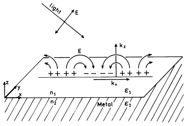
Schematic of surface plasmons on a metal surface. Adapted from [54].
Surface plasmons are also created by direct illumination of metal colloids (Scheme 2), resulting in rapid oscillation of the spatially bound electrons [58]. Colloids display vibrant colors because of a combination of absorption and scattering [59]. Unlike planar metal surfaces, no special conditions are required to observe the surface plasmon absorption in colloids. The term “absorption” is often used to describe colloids, but the more correct term is extinction because there are both absorption and scattering contributions to the colors.
Scheme 2.
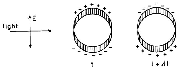
Surface plasmon oscillation in a metallic colloid. Adapted from [58].
In discussing fluorophore–metal interactions we use the terms far-field or far-field radiation to indicate a wave propagating in space away from its source. We use the term near-field to indicate the field around an oscillating dipole at distances closer than the wavelength. When discussing excited fluorophores we assume that the near-field is present while the molecule is in the excited state. The far-field wave exists after the molecule releases a photon and returns to the ground state.
The interaction of fluorophores with metals can be modeled as the interaction of an oscillating dipole with a conducting metal surface. A complete description of this theory would hide the important results with pages of complex equations. Also, there is no single theory for these interactions but rather there are a number of theories ranging from the simplest classical reflective models to quantum mechanical descriptions. Additionally, there are several theoretical models which can be used to describe the surface properties of metals. For the moment we will simply note that fluorophores radiate energy like oscillating dipoles [60]. As is true for any radiating dipole there can be near-field interactions or far-field radiation. We will present the minimum number of equations consistent with describing the concepts.
In the spectroscopy of biochemical systems we are accustomed to considering the molecular interactions of fluorophores with their environment, such as polarity effects on emission maxima or molecular contact between the fluorophore and the quenchers. Usually, we do not rely on physics and Maxwell’s equations to describe molecular fluorescence of biochemical samples. This is understandable because the complexity and specificity of molecular interactions is difficult to explain using Maxwell’s equations. However, after an examination of the literature, we believe that the interactions of fluorophores with metallic surfaces and particles can be accurately described using classical electrodynamics. This statement will come as no surprise to a physicist but may be less obvious to the practitioners of fluorescence spectroscopy. Electrodynamics can be used to describe fluorophores near metals because we are considering only the through-space interactions. Specific chemical and/or electron-transfer interactions can occur when fluorophores are very close to or in direct contact with the metallic surface, but we do not consider these molecular interactions in this report. A reader interested primarily in applications can skip to Applications of the radiative plasmon model.
Electromagnetic waves in dielectrics
To understand radiating plasmons we need to understand wavevector matching at an interface. This requires a mathematical description of the electromagnetic waves both in the dielectric sample and in the metal. Light propagating in space can be described as an oscillating wave [61–63]. The electric field of an electromagnetic wave propagating in the z direction can be described as
| (1) |
where kz is the wavevector, ω is the circular frequency (2π times the frequency in Hertz), t is the time, and δ is a constant describing the phase of the light at t = 0 and z = 0. The wavevector is related to the wavelength by kz = 2π/λ1; where λ1 refers to the wavelength in the medium where the light is propagating which has a refractive index n1. In a vacuum the refractive index is n0 = 1.0 and the wavelength is given by λ0. In medium 1 with a refractive index n1 the wavelength is given by λ1 = λ0/n1. When an electromagnetic wave moves from a vacuum to a medium with a higher dielectric constant n1; the wavelength decreases from λ0 to λ1 but the frequency remains the same. In molecular fluorescence, we typically refer to the wavelength as a single value as the light moves from air to the sample. In reality, it is the light frequency that remains constant and the wavelength varies with refractive index.
It is useful to have an intuitive understanding of wavevectors. The wavevector kz, can be understood as the rate of change of the electric field with distance along the z axis. The wave goes through one complete oscillation when the change in z is 2π/kz. In a vacuum the wavenumber is given by k0 = 2π/λ0. In medium 1 with refractive index n1 the wavevector is k1 = 2π/λ1 = n12π/λ0 = n1k0. For shorter wavelengths the electric field oscillates more rapidly with distance, so the wavevector is larger. Using c = λ0ω/2π, where c is the speed of light in a vacuum, it is easy to show that the free space wavevector for any frequency is given by k0 = ω/c.
When describing the behavior of electromagnetic waves at an interface, manipulations of expressions such as Eq. (1) become complex. For this reason, the formalisms use complex notation according to the Euler formula
| (2) |
where . Using this notation Eq. (1) becomes
| (3) |
It is understood that the physical quantities describing the electric field are given by the real part of Eq. (3). What is stated less frequently is that the complex term in Eq. (3) describes factors which attenuate the beam along its incident path, including absorption of the light and total internal reflection (TIR), both of which result in exponentially decaying fields.
When describing light at an interface it is convenient to allow the beam to propagate in any direction. Hence the z axis is replaced with an arbitrary direction r̄ so that
| (4) |
where m̄ is a unit vector along the direction of the electric field and
| (5) |
where Ẽ0 contains the phase shift which may occur at the interface.
It is valuable to recall how light attenuation is described using exponential notation and wavevectors. If a medium absorbs, light Eq. (4) can still be used, except that the wavevector becomes a complex number. For a wave traveling along the z axis Eq. (4) becomes
| (6) |
where the complex wavenumber is given by
| (7) |
Hence, Eq. (6) can be written as
| (8) |
The first exponential term describes the attenuation of the field as the wave travels through the absorbing medium. The second term describes the rate of oscillation along the z axis. The light intensity is proportional to square of the electric field so the intensity decreases as exp(−2κz). The absorption coefficient is given by α = 2κ.
These well-known equations for an oscillating wave allow us to clarify the meaning of the wavevector (k̄ or kz), also called the propagation constant for the wave. Most descriptions of reflection and refraction of light assume that the momentum of the wave is conserved at the interface. The momentum of a photon is proportional to the frequency. The laws of reflection and refraction are derived using momentum conservation, which is equivalent to wavevector matching at the interface. Wavevector matching requires that the electric field be continuous across the interface. Waves that cannot propagate in a medium are often described as imaginary or evanescent. Wavevector matching at a metal–dielectric sample interface determines the ability of the metal to absorb or a plasmon to radiate. Wavevector matching at a metal–dielectric interface is moderately complex but can be understood by first examining the interface of two dielectrics.
Refraction and reflection at an interface
We are all familiar with Snell’s law which describes the angles of a light beam passing through an interface. This law states that the angles from the normal in medium 1 and medium 2 are related by the refraction index of each medium by
| (9) |
This law can be derived in a variety of ways, using traveling wavefronts (Huggens’ Principle) or minimizing the time of travel (Fermats’ Principle), without explicit reference to wavevector matching at the interface. These approaches are less informative when considering nonpropagating or evanescent waves. We use the wavevector approach [61] because it provides an intuitive basis for understanding the factors that govern plasmon absorption or radiation from a metal interface.
Consider a wave incident on the interface from region 2 with refractive index n2 (Fig. 1). The incident wave can be described by
Fig. 1.
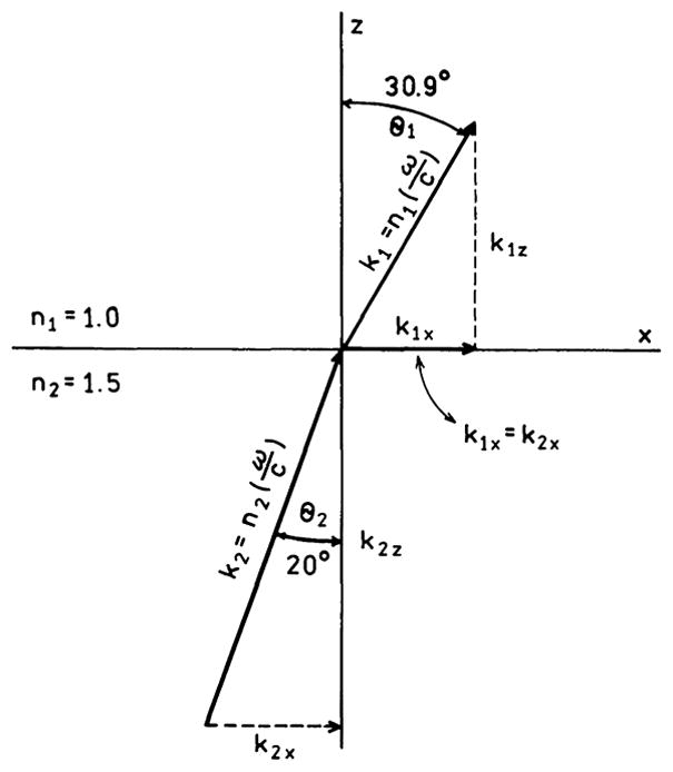
Wavenumber matching across an interface (x axis) of two dielectrics. The lengths of the arrows indicate the magnitude of the wavevector in each region.
| (10) |
where k̄2 is the wavevector and r̄2 is the direction of propagation in medium 2. The transmitted wave has the same frequency and can be described as
| (11) |
The complex amplitudes Ẽ01 and Ẽ02 account for any phase shifts. The electric fields of Ẽ1(r̄, t) and Ẽ2(r̄, t) have to be continuous across the interface. This requirement of continuity is equivalent to the wavevector matching at the interface at all points and at all times. Hence, continuity of the electric field across the interface requires that
| (12) |
Along the x axis, at the interface for z = 0, this equality becomes
| (13) |
recalling that k1 = k0n1 and k2 = k0n2 one obtains Snell’s law (Eq. (9)).
Most textbooks end the description at this point because the problem has been solved. However, it is valuable to examine Fig. 1 in more detail to obtain a mental picture of wavevector matching at the interface. Because of the difference in refractive index the wavevector is larger in region 2 than in region 1, which reflects the fact that the wavelength is shorter in region 2 than in region 1. Matching the wavevectors along the interface (x axis) requires equal projections of k̄1 and k̄2 onto the x axis. To satisfy k1x = k2x the beam in region 1 must propagate at a larger angle θ1 than the incident angle θ2. As θ2 becomes larger θ1 must also become larger. Because θ1 is always larger than θ2, θ1 reaches 90° before θ2. When this occurs the beam cannot propagate into region 1 (sin θ1 > 1.0) and total internal reflection occurs.
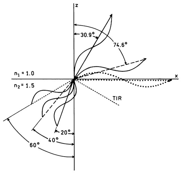
The phenomenon of TIR is illustrated in more detail in Fig. 2. Assume that the beam in region 2 is propagating toward the interface. The lengths of the lines indicate the magnitude of the wavevectors. Irrespective of the angles, the wavevector in region 2 is 1.5-fold larger than that in region 1. The x axis wavevectors above (k1x = k1sinθ1) and below (k2x = k2sinθ2) the interface are related by Eq. (13). For incident θ2 values of 20° (—) and 40° (– – –) it is possible to draw k̄2 to satisfy Eq. (13), at angles of 30.9° (———) and 74.6° (– – –), respectively. However, if θ2 = 60° (- - - -) the magnitude of k1 along the interface k1x (····) has to be larger than the total magnitude of k1. The beam incident at 60° cannot propagate into region 1 because the fields cannot be continuous across the interface. The beam cannot enter region 1 and is totally internally reflected. At the same time there exists an evanescent wave in region 1 where the field along the z-axis is attenuated exponentially, Eq. (8), where the rate of attenuation depends on n1, n2, and the angle of incidence θ2. As will be shown below, the possibility of wavevector matching across a metal–dielectric interface determines whether the plasmons can radiate or are trapped and dissipated as lossy surface waves.
Fig. 2.
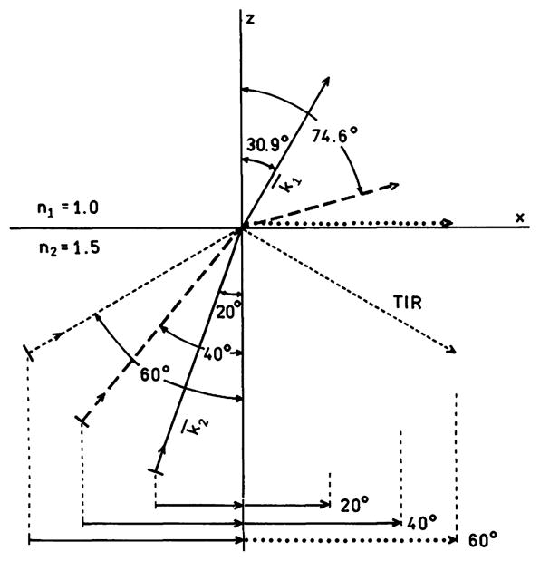
Wavenumber matching along the x angles for various angles of incidence in medium 2. The lengths of the arrows indicate the magnitude of the wavevectors in each region. The dotted line along the x axis represents a wavevector too large to exist in region 1.
For metals the beam does not propagate into the metal, except for a short distance known as the skin depth. Without a propagating beam it is more difficult to visualize electric field continuity. For this reason Fig. 3 shows wavevector matching with regard to the speed of wave propagation in each region. In this case the wavelength is longer in region 1 than in region 2 (λ1 = 1.5 λ2). When examining the traveling waves it is not necessary to match the projections on the x -axis. Instead one should visualize the fields matching as the waves travel faster in region 1 than in region 2 (v1 = 1.5 v2). For incident angles of 20° and 40° the beam can propagate in region 1. However, use of Eq. (9) at 60° requires that the electric field in region 1 travels faster than the speed of light. Since this cannot occur the beam in region 1 is evanescent and the beam is reflected back into region 2.
Fig. 3.
Transmission across an interface for various angles of incidence, shown as waves with different propagation speeds. The lengths of the lines represent the magnitude of the wavelength in each region.
Optical properties of metals
An understanding of the interaction of fluorophores with metals requires an understanding of the optical properties of metals. Our everyday experience with mirrors gives the impression that reflection is a simple phenomenon. In reality, the optical properties of metals are a complex topic and have been the subject of monographs and reviews [64–67,53]. When considering fluorophores near metallic surfaces we have to consider thick metal films or mirrors, thin metal films which display surface plasmon resonance, and colloids which display intense absorption. Why do mirrors reflect at all angles but thin films display strong surface plasmon absorption at wavelengths where mirrors are reflective? What is different between mirrors and colloids to cause one to reflect and the other to absorb light?
The optical properties of metals are easily described with regard to their refractive index (ñm) and dielectric constant (ε̃m), which for metals are complex numbers.
| (14) |
and
| (15) |
where it is understood that the values depend on frequency (ω). These complex properties are due to electrons which migrate freely but experience some resistance and to the interband transitions present in most metals. Typical interband absorptions are 4d → 5s in silver and 5d → 6s in gold. For the interactions with fluorophores we are concerned with the electron motions which can be analyzed with regard to a damped oscillator with an external driving force. The displacement of an electron with mass m and charge q by a distance x from the mean value is given by [61–63]
| (16) |
where γ is the damping constant and E0 cos (ωt) is the applied field. The natural frequency of a harmonic oscillator ω0 is a result of the restoring force for a bound charge. In a metal the electrons move freely so this term is omitted. Eq. (16) is usually written in complex notation as
| (17) |
Examination of Eq. (17) shows that the electron motions, and hence the optical constants, depend on the frequency of the applied field. Eq. (17) can be solved to yield the polarization induced by the applied field. The polarization and the definition of the dielectric constant are used to obtain the frequency-dependent dielectric constant of the metal:
| (18) |
This constant can also be written as
| (19) |
where ωp is the plasmon frequency of the electrons. This expression is called the Drude model. The appearance of the plasmon frequency ωp is confusing because we neglected ω0 for free electrons. The origin of ωp is due to the combined motions of part of the mass of free electrons from a background of fixed charges [54]. As the frequency increases the imaginary term increases and ε̃m(ω) becomes imaginary, which reflects the phase shift between the incident field and the induced field in the metal and attenuation of the field in the metal. If the damping constant γ is small there is no phase lag and
| (20) |
Such electron motions with γ = 0 are said to be collisionless.
The dielectric constant experienced by a wave incident on a metal depends on the incident frequency. At long wavelengths where ω < ωp the electrons follow the incident field, and the dielectric constant is negative. For a perfect metal the conductivity is infinite and the electrons on the surface precisely follow the incident field. The incident wave is then reflected with a 180° phase shift. Metals often approach such perfect behavior at low frequencies (long wavelengths). As the frequency increases the electrons are no longer able to follow the incident field and display a phase shift due to the finite conductivity. The real part of the dielectric constant then becomes less negative. Additionally, a mirror may not be 100% reflective. These phenomena are handled phenomenologically in Eqs. (14) and (15) by the optical constants of the metal. For metals with high conductivity the attenuation coefficient is large, meaning that the field penetrates only a short distance into the metal. This distance is called the skin depth dm. The skin depth of the field in the metal can be calculated from the optical constants. For gold and silver the skin depth is typically near 30 nm [54,68].
The behavior of the wave in a metal can be determined using Eq. (3), except for the wavevector which is now complex (Eq. (7)). The complex wavevector is obtained from the complex refractive index
| (21) |
Insertion of k̃m in Eq. (3) yields an expression for the wave in the metal
| (22) |
The imaginary component of the refractive index describes the attenuation and the real part of the refractive index gives the wavelength in the metal. Recalling that the intensity is the square of the field the absorption coefficient is given by
| (23) |
In metals the imaginary component of ñr is usually large, in the range of 3 to 6 for silver and gold in the visible, so the incident beam is strongly attenuated.
Optical properties of metal surfaces
We can now explain, on an intuitive basis, the interactions of incident light or nearby excited fluorophores with metallic surfaces. For a planar surface the maximum value of the in-plane wavevector of the incident light is given by kx = k0n1. At a dielectric–metal interface the surface plasmon wavevector is given by
| (24) |
where for simplicity we have written ε̃m(ω) as εm. For good metals and frequencies below the plasmon frequency, εm is typically large and negative and is dominated by the real component. Substitution of typical values for the optical constants of metals shows that wavevector matching at the dielectric–metal interface, when illuminated through the same dielectric, is not possible. For instance, at 600 nm the dielectric constant of silver is ε̃m = −14 + 0.45i. Suppose the dielectric has . Substitution into Eq. (21) using the real part of ε̃m yields a ratio of ksp/k1 = 1.09. The wavevector of the incident light is less than ksp, and wavevector matching at the interface is not possible. The wave cannot penetrate the metal and is reflected. One can interpret the large values of ksp > k1 as due to the charges being more closely spaced on the metal surface than the peaks and valleys of the incident field. This is why surface plasmon resonance in thin films is observed using light incident on the metal through a high refractive index prism [54]. The prism shortens the wavelength of light incident on the film (Scheme 3). This shortening has no effect on the absorption at the prism–metal interface because ksp is still larger than the incident wavevector through the prism. However, if the refractive index is lower on the distal or sample side of the thin film, Eq. (21) can be satisfied at the metal-sample interface when the film is illuminated through a prism. When wavevector matching occurs, light is absorbed and the reflectivity is decreased. The prism can have a modest refractive index since it is necessary to increase the incident wavevector only by about 10%. The surface plasmons on the metal surface create an evanescent field which penetrates into the sample. This is the evanescent field which is responsible for the shifts in reflectivity observed in surface plasmon resonance. For silver and gold at 600 nm the evanescent field penetrates about 300 nm into the sample. The surface plasmon trapped at the sample–metal interface also creates an evanescent field in the metal, which penetrates about 30 nm into the metal [67].
Scheme 3.
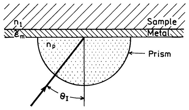
Geometry for surface plasmon resonance.
Similar reasoning can explain why some plasmons can radiate out of the film (RP) and others are nonradiative plasmons (NRP). Assume that an induced charge separation exists at a metal–sample interface (Fig. 4). If the charge distribution is widely spaced then the in-plane wavevector is small and a radiating wave can be generated with a wavevector k1 (Fig. 4, top). If the charges are more closely spaced then the in-plane wavevector increases (Fig. 4, middle). To keep the electric field continuous across the interface the wavevector k1 must be at a larger angle relative to the normal (Fig. 4, middle). If the charges become still more closely spaced then the inplane wavevector exceeds the k1 even if k1 is parallel to the interface. If this closely spaced charge separation is induced by light or a nearby fluorophore then the length of the wavevector in region 1 is fixed. At this point the plasmon cannot radiate out of the metal. Because the plasmon decay times are very short [69], a plasmon which cannot radiate decays into heat.
Fig. 4.
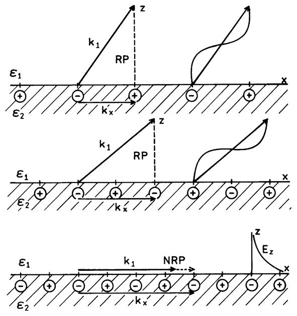
Schematic of in-plane wavevector matching for surface plasmons. In the lower panel the plasmons are nonradiative and the field in medium 1 is evanescent.
This interpretation of radiating and nonradiating plasmons provides insight into the use of metals to enhance fluorescence detection. Suppose an excited fluorophore in region 1 is near to (≈50 nm) or distant from (≥500 nm) the metal (Fig. 5). The distant fluorophore can interact with the metal only by the far-field radiation, which must satisfy Eq. (24). If the fluorophore is distant from the metal the charge distribution induced on the metal surface will be widely spaced. If the fluorophore is close to the metal the interactions are via the near-field and the charges are more closely spaced. Fluorophore close to the metal may induce such closely spaced charges. These plasmons cannot radiate and the emission is said to be quenched. If the fluorophore is distant from the metal Eq. (24) cannot be satisfied; the field is reflected, resulting in lifetimes which oscillate as a function of distance from the metal [1,2]. However, if the excited fluorophore is close to a thin film on a prism Eq. (24) can be satisfied by radiation into the prism (Fig. 5, top).
Fig. 5.
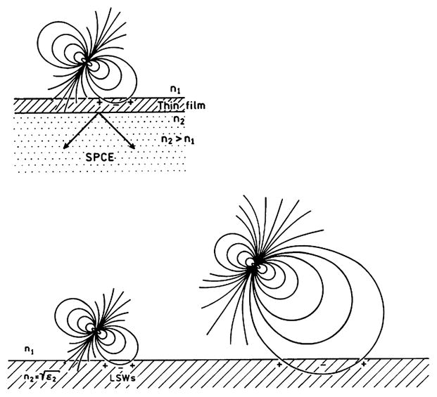
Excited fluorophore interacting with a thick metal surface via the near-field or the far-field. The top shows the near-field interaction with a thin metal surface.
The ability or inability of a plasmon to radiate into medium 1 can be determined by a simple inequality. By examination of Fig. 1 one can see that [54]
| (25) |
For the energy to radiate into medium 1 the wavevector k1z must be real. If , then k1z is imaginary, meaning that the field is evanescent in region 1. On the other hand if , then k1z is real and the plasmon can become a far-field propagating wave. At first glance these inequalities may not have intuitive meaning. The first inequality says that the in-plane wavevector of the plasmon is larger than the wavevector of a propagating wave in region 1. This is similar to TIR at an interface of dielectric when the incident angle exceeds the critical angle. Similarly, the second inequality says that the in-plane wavevector is smaller than that of the propagating wave. Hence the plasmon can radiate but at an angle from the normal to satisfy Eq. (24).
This concept is the basic premise of the radiating plasmon model. The excited fluorophore induces a charge distribution on the metal surface. If this plasmon can radiate then the fluorophore emission is observed as plasmon-coupled emission. If the induced plasmon cannot radiate then the fluorophore appears to be quenched. Nothing is fundamentally different in the fluorophore–metal interactions, which are still described by classical electrodynamics. The difference between enhanced fluorescence and quenching is the nature of the induced plasmons on the metal surface.
The mechanisms by which excited fluorophores create the plasmons are not always clear, at least for the case of SPCE. Several groups have studied quenching at metal surfaces [48,70,71]. The lifetime of the fluorophores decreases as they approach closer than about 10 nm to the surface. These quenching effects have been explained with regard to Forster transfer to the metal which behaves as a plane or half-space filled with dipolar acceptors. However, it appears that SPCE occurs over distances of 100 nm or more, which is too long for Forster transfer. Additionally, the lifetimes did not appear to be dramatically decreased [36–38] as expected for Forster transfer. Other groups reported decrease in lifetime at distances up to 100 nm [72,73]. There appears to be a difference in the interaction of fluorophores with thick or thin metal films. There appears to be a resonance interaction which results in coupling of excited fluorophores with surface plasmons, and this interaction occurs over much larger distances than Forster transfer [17]. The nature of the fluorophore–metal interaction during SPCE requires additional study.
Optical properties of metal colloids
In contrast to continuous metal surfaces, metal colloids display intense colors which are due to a combination of both absorption and scattering. In a mirror the electrons can move over larger distances. In metallic colloids the distances are limited by the size of the particle. This results in the creation of dipoles and higher order moments. There have been numerous papers and monographs on this topic. The optical properties agree reasonably well with Mie theory which considers small spherical particles and particles with a size comparable to the incident wavelength. The theory is relatively simple for spheres. In this case the cross section for extinction for a particle with a dielectric constant ε1, is given by [74–78]
| (26) |
where k1 = 2π n1/λ0 is the wavevector of the incident light in medium 1 and α is the polarizability of the sphere of radius r,
| (27) |
where εm is the complex dielectric constant of the metal. The term |α|2 is square of the modulus of α. In Eq. (26) the first term represents the cross section due to absorption (CA) and the second term the cross section due to scattering (CS). If the particles are larger than about 0.05λ or are not spheres the theory becomes considerably more complex. When discussing the cross sections of colloids it is convenient to use the efficiencies (Q) for extinction (E), absorption (A), and scattering (S), QE, QA, and QS, respectively [75,76]. These values are obtained by dividing the cross sections for interaction with light by the geometric cross sections πr2. These efficiencies represent the ability of the particle to scatter light outside its physical cross sectional area. These efficiencies being greater than unity is the reason that the field near the surface of a particle can exceed the average incident field in the medium.
When considering metal-enhanced fluorescence we expect the absorption term (CA) to cause quenching and the scattering term (CS) to cause enhancement. Examination of Eq. (26) shows that CA increases as r3 whereas CS increases as r6. For this reason we expect larger metal colloids to be preferred for metal-enhanced fluorescence.
Decay processes for a dipole near a mirror
The widely held perception that fluorophores close to metallic surfaces (d < 10 nm) can only be quenched can be traced to the Drexhage experiments and subsequent interpretations. Fig. 6 shows the normalized lifetimes for a Eu3+ complex positioned in front of a silver mirror using Langmuir–Blodgett (LB) films [79]. The lifetimes oscillate with distance from the mirror. The oscillations in lifetime for d ≥ 100 nm can be explained by reflection of the field induced by the dipole back onto the dipole, which is called the reflective model [80]. The data also show a dramatic decrease in lifetime when the dipole is within 10 nm of the surface. This decrease is interpreted as due to lossy surface waves which quench the fluorophore at short distances. For accuracy we note that precise agreement of the Eu3+ data with the reflective model requires consideration of the sample thickness and the sample–air interface, but this effect is not relevant for the present discussion.
Fig. 6.
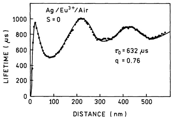
Normalized lifetimes for a Eu3+ complex in front of a silver mirror. The solid line is the best fit using a model which includes lossy surface waves. From [79].
Electrodynamic theory can be used to calculate the decay rates for an excited state population which decays by LSWs or transfer to surface plasmons or decays to far-field radiation [18]. This calculation shows that fluorophores more distant than about 300 nm decay primarily by radiation (Fig. 7). Transfer to plasmons occurs at distances up to 400 nm. Transfer to the LSWs dominates the decay for distances below 10 nm. The decay rates in Fig. 7 were used to calculate the fraction of the total excited state population which decays by each route (Fig. 8). Radiative decay dominates above 100 nm, transfer to surface plasmons occurs from 10 to 400 nm, and quenching by LSWs is the dominant process below 10 nm (Fig. 8). These results have created the impression that decay by the LSWs can only quench the emission and close proximity of fluorophores to metal surfaces is a problem to be avoided.
Fig. 7.
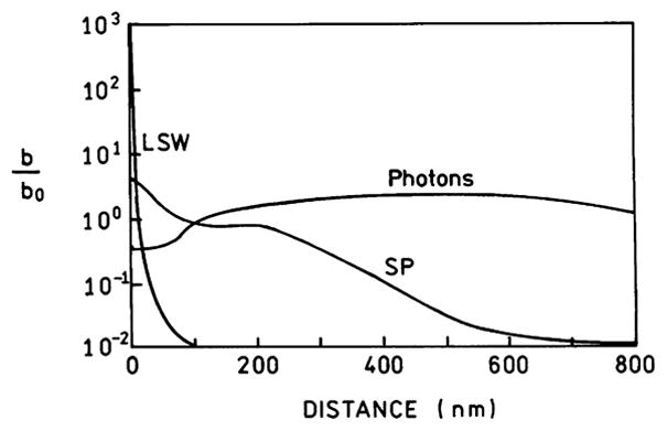
Calculated decay rates for a 633-nm dipole radiating to a silver mirror or to far-field radiation. Data taken from [18].
Fig. 8.
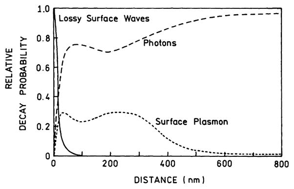
Relative probability of a dipole radiating at 633-nm for decay into lossy surface waves, surface plasmons, and far-field radiation. From [18].
It seemed logical to us that a fluorophore near a metal surface would induce electron oscillations even within 10 nm of the surface. We questioned why the mechanism of interaction should change from quenching by LSWs to transfer to plasmons as the distance increased from 3 to 300 nm. The interaction mechanism should not change with distance, so that the LSWs and surface plasmon mechanisms are the same phenomenon. As the fluorophore gets closer to the surface the induced electron oscillations in the metal become more closely spaced. The plasmons cannot radiate because the wavevectors cannot be matched, in a manner analogous to that in Fig. 1 with total internal reflection. For example, suppose the fluorophore is near a thin metal film (Fig. 5, right). In this case the plasmons or LSWs can radiate into the glass under the metal film because the plasmons at the metal–sample interface can match wavevectors (Eq. 24) with a radiating wave in the glass substrate with n2 > n0. We believe that this mechanism is the origin of SPCE. Fluorophores close to metal surfaces can create radiative plasmons at short distances, and this process does not necessarily result in quenching. The energy from the LSWs can be recovered as far-field radiation if the optical constants and the local geometry permits these plasmons to radiate.
The distinction between LSWs and radiating plasmons is not trivial. The realization that a fluorophore near a metal can create radiative plasmons, even at distances where the emission is usually quenched, results in a completely different way of thinking about fluorophore–metal interactions. Additionally, an understanding of what factors govern conversion of plasmons into far-field radiation clarifies numerous observations on fluorophores near metals. This understanding can also guide the rational design of radiating fluorophore–metal structures. For accuracy we note that this relationship between LSWs and radiative plasmons must be contained within the electromagnetic description of these interactions. However, we have not found any suggestion in the literature that the LSW component of the decay can be modified to generate useful emission.
Theory for fluorophores near a metallic surface
A complete electrodynamic description of fluorophore–metal interactions is beyond the scope of this report. Instead we describe some general results which explain the phenomenon of radiative or nonradiative plasmons. Consider an oscillating dipole above a metallic surface (Fig. 5). This dipole (μ) can be described by
| (28) |
where b = 1/τ is the inverse lifetime and Δω is the frequency shift caused by the metal. The reflected field is given by
| (29) |
Note that the decay rate of the reflected field is the same as the decay time of the fluorophore. The frequency shift Δω is small and can be ignored [18]. Calculation of the effect of the metal on the fluorophore requires calculation of only the reflective field. The ratio of the decay rates in the absence (b0 = 1/τ0) and presence (b = 1/τ) of metal is given by [18]
| (30) |
where q is the quantum yield, n1 is the refractive index surrounding the dipole, k1 is the wavevector for frequency ω in medium 1, and Im(ẼR) is the reflective field at the dipole. Eq. (30) can be used to calculate the relative decay rate for dipoles parallel (||) or perpendicular (⊥) to the metal surface. These expressions are
| (31) |
and
| (32) |
where the reflection coefficient of the parallel R|| and perpendicular R⊥ components of the field are given by
| (33) |
and
| (34) |
The values of lj are given by lj = −i(εj/ε1−μ2)1/2 or explicitly by
| (35) |
and
| (36) |
For this system of a fluorophore in front of a mirror the total decay rate is given by
| (37) |
which is different from the usual expression fluorophores in the absence of a mirror.
From examination of these equations it is difficult to understand what factors determine whether the system radiates or is quenched. Additional insight is obtained when the expressions are simplified to the far-field model. In this case the variable μ reduces to μ = kx/k1 = sin θ where θ is the angle from the normal axis. The meaning of Eqs. (31) and (32) now become clear. When sin θ < 1 this portion of the integral is real and describes energy radiating away from the interface. When sin θ > 1 this portion of the integral is imaginary and describes the decaying evanescent field. The plasmons create an evanescent field in medium 1, just as a totally internally reflective beam creates an evanescent field in the distal medium. These plasmons are trapped and dissipate rapidly.
Interpretation of the integrals in Eqs. (31) and (32) can also be stated in a different way [17]. The integral from 0 to 1 is real and results in far-field radiation. The integral from 1 to infinity is imaginary, resulting in nonradiative fields. At μ = 1 the field created by the dipole is in resonance with the surface plasmons. This interpretation of the integrals explains why induced electron oscillations become nonradiative when the fluorophore is close to the surface. When the fluorophore is distal from the surface the field is reflected because wavevector matching is not possible. When the fluorophore is closer to the metal electron, oscillations are still induced in the metal, but the wavevectors are too large (charges are too closely spaced) and the plasmons cannot radiate. This interpretation implies that fluorescence enhancement or quenching is determined by the ability of the induced plasmons to radiate. Even those plasmons created at short fluorophore-to-metal distances can radiate if the structure is designed to allow matching of the wavevectors.
Increased quantum yield with plasmon-coupled emission
The lifetimes of plasmons are very short, typically near 10 fs [68,69]. This suggests that energy transfer is essentially one way, fluorophore to metal. The increase in quantum yield for a fluorophore near a metal surface can be understood as a result of rapid energy transfer to the plasmons which then radiate to the far-field. This concept was described previously for donor–acceptor pairs and Forster transfer. We showed theoretically and experimentally that rapid energy transfer from a donor to an acceptor resulted in an increase in overall quantum yield of the system if the acceptor displays a higher quantum yield than the donor [81,82]. This effect occurs because the rate of Forster transfer is proportional to the radiative rate of the donor and is independent of the nonradiative decay rate. If the transfer rate is high the energy is transferred before the donor can decay by the nonradiative pathway which is the same in the absence and presence of the acceptor.
The effect of energy transfer to the metal on the overall emission at the fluorophore emission maximum may be clarified by some simple equations. Recall that the rate of transfer to an acceptor or group of acceptors is given by
| (38) |
where n = 4 or 3 for a plane or filled half-space of acceptors, respectively, R0 is the Forster distance, r is the distance from the fluorophore to the acceptor, and τ0 is the lifetime of the donor fluorophores in the absence of acceptors. In this case the acceptors can be the metal surface or typical fluorophores. Recall that the quantum yield (Q0) and lifetime (τ0) of the donor in the absence of metal are given by
| (39) |
and
| (40) |
where Γ is the intrinsic decay rate and knr is the nonradiative decay rate in the absence of metal. The efficiency of energy transfer into the plasmons is given by
| (41) |
As the rate of transfer becomes larger than the inverse lifetime, the transfer efficiency approaches unity.
Now consider the total emission intensity (IT) due to the fluorophore (IF) and the radiating plasmon (IP). The total intensity is given by
| (42) |
where QS is the scattering quantum yield, εF is the absorption coefficient of the fluorophore, and k is an instrument constant. In Eq. (42) we have assumed that the plasmons are not directly excited or if they are directly excited then the light is removed by a filter which does not transmit the incident wavelengths. As the transfer efficiency approaches 100%, the total intensity becomes
| (43) |
so that the effective quantum yield of the fluorophore approaches unity and the overall quantum yield becomes the quantum yield for scattering, irrespective of whether the quantum yield (Q0) of the fluorophore is low or high. We believe that a similar effect occurs with energy transfer to plasmons in thin films. For fluorophores near the thin metal film energy transfer is nearly complete, so that the overall quantum yield becomes the quantum yield of the plasmons. These expressions (Eqs. (39)–(43)) provide a basis for predicting the intensity increase due to enhanced emission for a fluorophore near a metal surface. In the case of colloids we have some information on the scattering efficiency [73,74]. However, we have not found reports on the quantum yield of plasmons in thin films.
Applications of the radiative plasmon model
Metal-particle-enhanced fluorescence and colloid extinction spectra
During the past several years we have investigated the effects of silver and gold particles on nearby fluorophores. In numerous experiments with silver particles and a lesser number with gold particles, we found that silver island films generally increase fluorescence intensity and decrease the lifetime [24–29]. SIFs have a heterogeneous distribution of particle sizes and display plasmon absorbance. We extended the experiments with silver particles to include suspensions of silver colloids. These efforts usually failed to yield enhanced fluorescence, except for an occasional increase which was difficult to reproduce. Similarly, gold colloids were found to quench fluorescence but occasionally increased fluorescence. In contrast to colloids in suspension we observed enhanced fluorescence from silver colloids when bound to a glass surface [28]. We did not know whether the increased intensity was due to colloid–colloid proximity on the glass surface or to an enhancement effect due to individual colloids. For colloids in suspension it was difficult to interpret small intensity changes because of experimental problems purifying colloids with bound fluorophores from the unbound fluorophores.
In retrospect these diverse observations can be explained by the RP model and the optical properties of colloids. Metallic colloids are known to display brilliant colors due to plasmon resonances which depend on the size and shape of the particles [83]. The extinction coefficient of metallic colloids is due to two components, absorption and scattering [74–78]. The relative contribution of absorption and scattering depends on the metal and on the size of the colloids. The scattering component of the extinction is a measure of the extent to which the plasmons can radiate into the far-field. The incident light induces oscillating charges in the colloid. The oscillatory charges can radiate the energy as a far-field propagating wave. According to the RP model the absorption of the colloids will cause fluorescence quenching and the scattering component will cause enhanced fluorescence.
The usefulness of separate consideration of the absorption and scattering components of the extinction can be seen from several examples. Figs. 9 and 10 show the contributions of absorption and scattering for small and large silver and gold colloids [81]. For a small 22-nm-radius silver particle the extinction is due to both absorption and extinction, both sharply centered at 400 nm. Because there are both absorption and scattering components it would be difficult to predict whether 22-nm silver particles will act as a quencher or enhancer of fluorescence. For a larger silver particle (100-nm radius) the extinction is due almost completely to scattering. Hence we predict that silver particles with a radius near 100 nm will enhance fluorescence at wavelengths from 500 to 700 nm. Fig. 10 shows similar data for 22- and 100-nm-radius gold particles. The extinction of the smaller 22-nm gold particle is due almost completely to absorption and the particle is likely to quench fluorescence. The larger gold particles display a dominant scattering component above 600 nm and should enhance fluorescence of fluorophores emitting at wavelengths longer than 600 nm. From additional data in [81] (not shown) one can predict that 100-nm-radius copper colloids will enhance fluorescence above 700 nm.
Fig. 9.
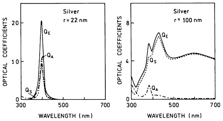
Extinction, absorption, and scattering spectra of small and larger silver colloids. Adapted from [84].
Fig. 10.
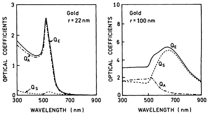
Extinction, absorption, and scattering spectra of small and large gold colloids. Adapted from [84].
It is informative to examine the effects of particle size on the scattering and absorption of gold and silver particles. Fig. 11 shows this dependence for silver and gold colloids [77,78]. The scattering efficiency Qs of silver particles less than 20 nm is small, but the scattering efficiency is high (over 5) for sizes of 30 nm or larger. For gold colloids the scattering efficiency is not high (over 2) until the radius is 40 nm or larger. Thus for enhanced fluorescence from silver and gold colloids the RP model predicts the need for radii over 20 and 40 nm, respectively. For enhanced fluorescence it may be important to consider the fraction of the light interacting with the colloid which is scattered (ϕs). This value is defined as ϕs = CS/CE = CS/(CA + CS). For both silver and gold colloids the scattering efficiency approaches unity for larger particles. This suggests that larger metallic colloids are likely to be preferred for metal-enhanced fluorescence and that the optimal size for metal-enhanced fluorescence is near 40 nm.
Fig. 11.
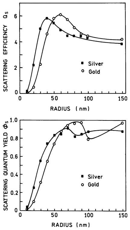
Effect of spherical particle size on the scattering efficiency QS and the scattering quantum yield (ns) of silver and gold colloids. In the top panel the wavelength represents the long wavelength absorption maxima for a colloid of this size. Data from [77,78].
Changes in scattering cross sections can be used to modify fluorescence
Many biochemical assays require the detection of binding interactions between proteins or nucleic acids. If the biomolecules are bound to the colloid surfaces, the colloids can be brought into close proximity by affinity reactions. It is well known that the plasmons of nearby colloids can interact, resulting in shifts in the extinction spectra [85–88]. Fig. 12 shows theoretical calculations [89] for two gold colloids as they are brought closer together. The extinction spectra shift toward longer wavelengths as the distance decreases. Fig. 12 does not show what portion of the extinction is due to absorption or scattering. However, other experimental and theoretical results have shown that the increased extinction at long wavelengths for aggregated colloids is dominantly due to scattering [90]. This suggests that metal-enhanced fluorescence will occur when two interacting colloids display a longer-wavelength absorption. Because of the ease of measuring absorption spectra these shifts due to colloid–colloid interactions have been used to develop a number of bioaffinity assays for proteins [91–95] and nucleic acids [96,97].
Fig. 12.
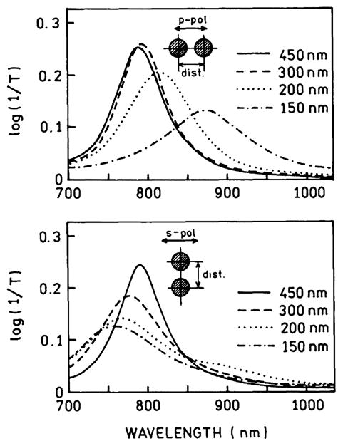
Extinction spectra of two gold colloids with varying distance between the colloids. The colloids were assumed to have a diameter of 150 nm. Revised from [89].
Separation of the absorption and scattering components of colloid clusters can be used to predict when cluster formations should result in metal-enhanced fluorescence. One example is shown in Fig. 13 (top) for gold colloids with surface-bound complementary oligonucleotides [98]. Oligonucleotide hybridization resulted in the formation of moderate-sized aggregates. The aggregated colloids show a decreased maximum extinction and a shift in the extinction to longer wavelengths. The bottom panel of Fig. 13 shows calculated spectra for an isolated 13-nm-radius gold sphere and an aggregate of spherical colloids. At wavelengths longer than 600 nm the extinction is dominated by scattering. This result suggests that enhanced fluorescence may be found for-fluorophores near gold clusters if the emission maxima of the fluorophore is above 600 nm.
Fig. 13.
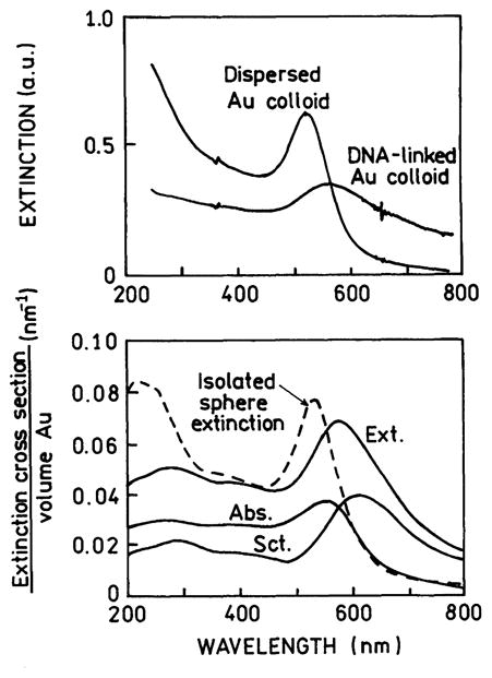
(Top) Extinction spectra of dispersed gold colloids and gold colloids linked by DNA. (Bottom) Calculated extinction, absorption, and scattering spectra for an isolated 13-nm-radius gold sphere and for a cluster of gold colloids. From [98].
Considerable information on the extinction spectra of interacting colloids is available. It is known that two or more colloids within a distance comparable to that of their radii display long-wavelength shifts in their plasmon absorption [99]. Changes in the plasmon extinction spectra have been studied theoretically [99–101]. Consideration of the effects of colloid aggregation on scattering efficiency may provide a rational approach to using similar colloidal preparations for assays based on metal-enhanced fluorescence.
Single particle detection with metal colloids
In many situations it is desirable to detect single particles or binding of a small number of fluorophores to a particle. In this case it is desirable that the individual colloid provides maximum enhancement of the fluorescence. This can be accomplished by selection of the shape of the particle. Fig. 14 shows spectra for two similar-sized silver colloids with different shapes [102]. The spherical silver colloid displays its maximum scattering cross section near 400 nm. The elongated silver colloid displays its maximum scattering cross section near 660 nm. Based on these spectra we expect the spherical 50-nm silver colloids to enhance fluorescence near 400 nm and the ellipsoidal colloid to be more efficient for enhancing fluorescence at 700 nm.
Fig. 14.
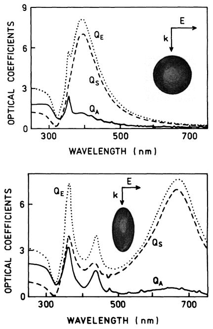
Calculated spectra for 50-nm-effective-radius silver colloids. The spheroid in the bottom panel has an axial ratio of 3 to 1 and the same volume as a sphere with r = 50 nm. From [102].
The use of appropriately shaped colloids for high-sensitivity detection has considerable potential to increase the intensity per particle by 10- to 100-fold. Fig. 15 shows the scattering intensity of a colloid as the axial ratio is increased from 1 to 7. As the particle is elongated 7-fold the scattered intensity increases 100-fold [10]. Ten years ago it may have been a challenge to obtain such elongated metal particles. However, synthetic methods are rapidly appearing to make silver [102,103] and gold [104–106] nanorods and other silver [107–109] and gold [110–112] shapes. Such particles with coupled fluorophores may be useful for intracellular single-particle detection, single-particle counting flow assays, and high-sensitivity detection using such particles in suspensions or bound to substrates.
Fig. 15.
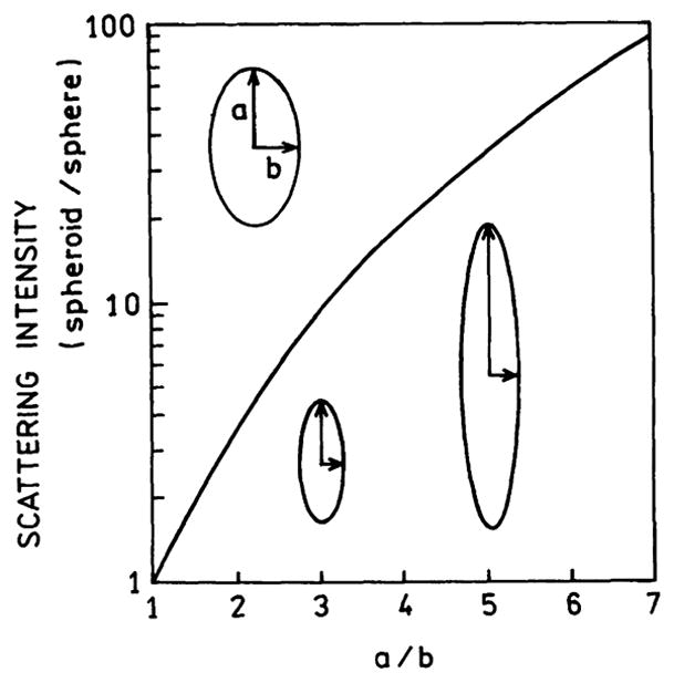
Scattering intensity of a spheroid relative to a sphere. Adopted from [10].
Another approach to colloid-based metal-enhanced fluorescence assays could be based on the effects of local refractive index on the plasmon resonance. This is the same phenomenon which is used in SPR, except that the refractive index changes are around a colloid rather than a planar metal surface. One example is shown in Fig. 16 which shows the effect of the dielectric constant on the plasmon absorption of a gold colloid 16 nm in diameter [113]. Further calculations are required to determine the change in the absorptive and scattering contribution at each wavelength and the extent to which these components can be changed in practical applications.
Fig. 16.
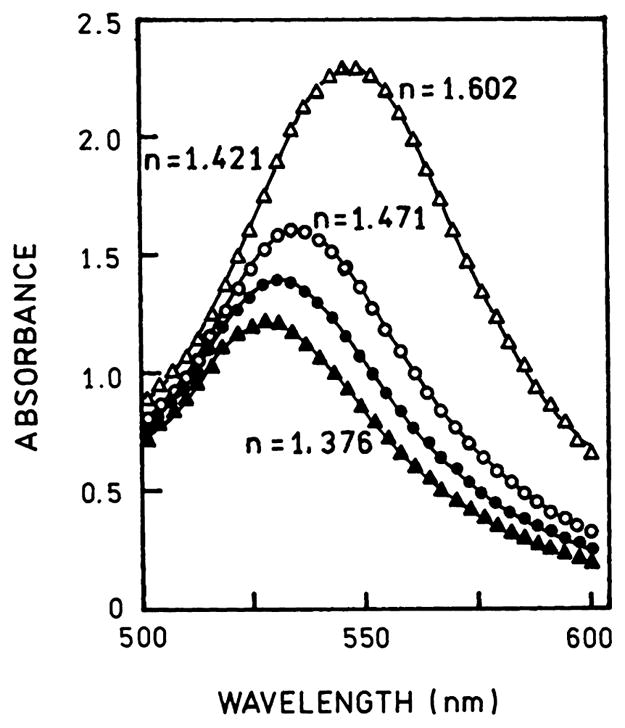
Effect of dielectric constant on the extinction spectra of a 16-nm gold colloid. From [113].
Radiating plasmons and surface-plasmon-coupled emission
In recent reports we described the observation of directional emission due to fluorophores at short distances from thin silver, gold, and aluminum films [38–40]. By “thin films” we mean continuous surfaces with thicknesses near 50, 50, and 20 nm, for silver, gold, and aluminum, respectively. Visual examination of these films shows them to be optically dense and nearly opaque. Nonetheless, excited fluorophores near the surface result in directional emission into the substrate. We attribute this signal to surface plasmons which radiate after being created by the excited fluorophores. At present we do not know the efficiency with which the plasmons radiate into the substrate. We suspect that the quantum is less than 100% but it must be reasonably large. Unfortunately, we could not find information on the efficiency of plasmon radiation from metal films. We found one report which states that the efficiency in their case is 10–20%, but there is no information on how this value was determined [114]. To maximize the SPCE signal and detection efficiency it is desirable to increase the coupling efficiency of the fluorophores with the surface and the radiative efficiency of the plasmons. A suggestion for obtaining higher SPCE intensities comes from surface-enhanced Raman scattering, which is typically performed on roughened silver surfaces. There have been extensive theoretical studies of the optical properties of surface roughness on the surface plasmons [115,116,47]. The overall conclusion is that surface roughness results in an increase in coupling of the incident light with surface plasmons, even if illumination is not done through a prism.
What can be done to increase the efficiency of SPCE from thin metal films? Recent reports have shown that surface roughness and/or particles near a metal surface can increase the intensity of scattered plasmon emission from thin metal films, that is light scattered at the incident wavelength without the presence of fluorophores. A typical sample, shown in Fig. 17 [117–119], consists of silver particles above the aluminum or silver film. The sample is illuminated from the air side at normal incidence, where surface plasmon absorption is not expected because wavevector matching cannot occur with a smooth metal surface. The sample was observed through a coupling prism which allows the plasmons to radiate (Fig. 17). Silver particles had a dramatic effect on the intensity of plasmon emission (Fig. 18). The largest effect was found when the particles were directly on the aluminum surface. A cone of plasmon emission, shown as a sketch, is observed with maximal azimuthal intensity in the direction of the incident polarization. Similar experiments have been done using illumination through the prism and measuring plasmon emission into the air, where plasmon emission would not normally occur (not shown). The scattering intensity is higher at longer wavelengths (Fig. 19), suggesting that the coupling of excited fluorophores onto radiating plasmons will also be more efficient at longer wavelengths.
Fig. 17.
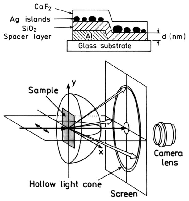
Sample configuration and experimental geometry use to measure particle-enhanced surface plasmon emission. From [117–119].
Fig. 18.
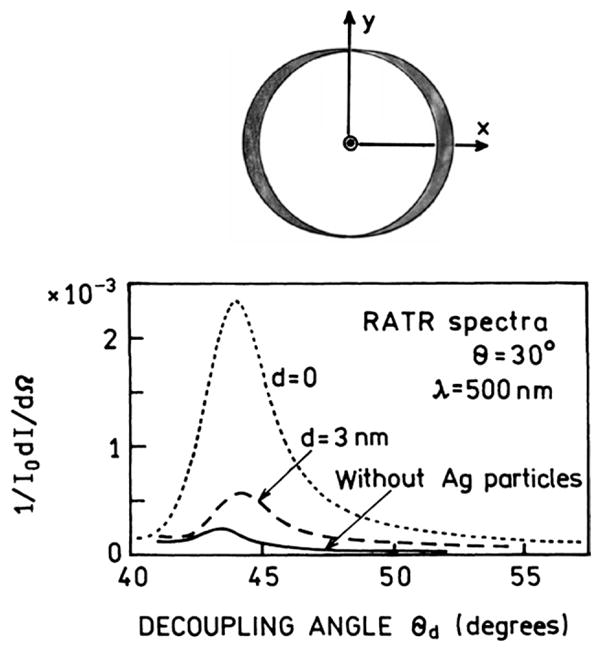
Effect of silver particles on plasmon emission (bottom) and a sketch of the cone of plasmon radiation (top). The incident light was polarized along the x axis. From [47,117–120].
Fig. 19.
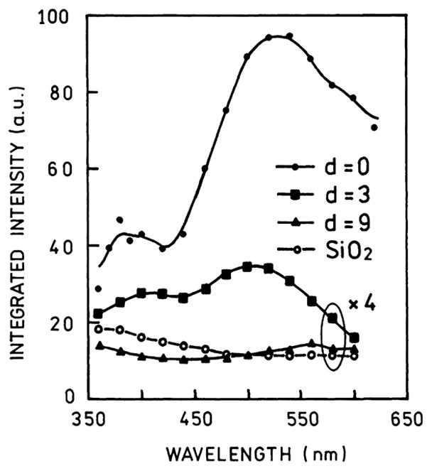
Scattered plasmon intensity at various wavelengths for the sample shown in Fig. 17. From [118].
There have been a number of theoretical studies of the effects of surface roughness on plasmon emission [121–123], which explain this effect as due to roughness-induced wavevector matching. There have also been theoretical studies of the effects of rough surfaces on the decay rate of nearby molecules. Such surfaces are expected to increase the decay rate. The theory and these experimental results suggest that moderate amounts of surface roughness can be used to obtain increased intensities of SPCE either back into the prism or away from the prism.
Surface-plasmon-coupled emission with metal gratings
Another opportunity suggested by the RP model is the emission of fluorophores placed directly on silver gratings [124–129]. We were always puzzled by emission from fluorophores directly on grating but quenching of fluorescence for fluorophores directly on mirrors. This difference can be understood by the effects of the grating on the in-plane wavevectors. The periodic structure provides a mechanism for the plasmons to radiate into the far-field. Without such a pathway the plasmons cannot radiate and are trapped, and the energy is dissipated. Conveniently, the various wavelengths radiating away from the grating will appear at different angles. This will provide intrinsic separation of incident light and plasmon-coupled emission from the fluorophores on the grating.
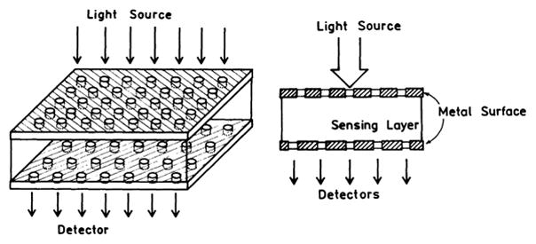
Another interesting observation was made using thin silver grating where the metal was about 50 nm thick [130–133]. In this case fluorophores on the grating displayed plasmon-coupled emission through the grating, with different wavelengths appearing at different angles. Plasmon-coupled emission through the grating provides opportunities for novel fluorescence-sensing-configurations. Fig. 20 shows an example where a sensing layer is positioned above the thin film grating. Emission from the sensing layer will couple through the grating and could be observed with closely spaced and/or proximity focused detectors. Ratiometric sensing should be possible using the wavelength separation provided by the grating.
Fig. 20.
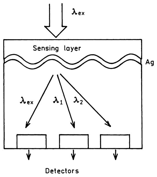
Fluorescence-sensing module based on grating-coupled plasmon emission.
Plasmon engineering to transport and radiate plasmons
In 1998 a report appeared [134] which showed that thick metal films with a regular array of holes can display extraordinary optical transmission greatly in excess of the transmission expected based on the open area of the holes. This effect is shown schematically in Fig. 21. The silver film was 300 nm thick, which is opaque in the absence of holes. If the films contained nanoholes there was efficient transmission through the films, much more efficient than would be expected from the size of the holes. The transmitted wavelength depended on the size and spacing of the holes. This observation resulted in theoretical studies to explain this effect [135–137]. It is now thought that the transmission is due to the creation of surface plasmons on one surface, migration of the plasmons through the holes, and subsequent radiation of the plasmons from the distal side of that metal. Such films should be useful in fluorescence devices. The transmitted radiation is strongly dependent on wavelength, so that the films may be used both as an excitation filter and for the creation of far-field radiation (Fig. 22). For example, the hole spacing of the top metal layer could be selected to transmit the excitation wavelength and the spacing in the lower layer to transmit the emission wavelength.
Fig. 21.
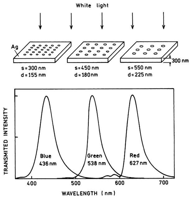
Light transmission through perforated but otherwise opaque silver films; s and d refer to the interhole spacing and diameter, respectively. Figure drawn from results in [134].
Fig. 22.
Fluorescence sensing device base on plasmon transport through a metal surface with a regular array of holes.
Even more elegant configurations are possible by combining plasmon engineering with nanoengineering, which can be used to obtain strongly directional emission. One example is shown in Fig. 23, for an array of parallel lines etched through the metal [138–140]. This structure serves as a type of monochromator in that light near 600 nm is transmitted most efficiently. Importantly, the transmitted light radiates only at defined directions into the far-field on the distal side of the metal and the various wavelengths radiate in different directions. An even more remarkable result is shown in Fig. 24 for a metal film with open concentric rings. In addition to being wavelength selective, the transmitted light migrates as a narrow beam into the far-field.
Fig. 23.
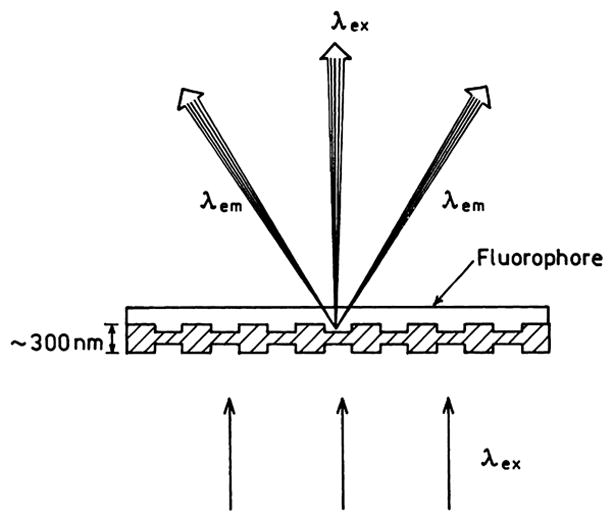
Directional and diffracted emission from a fluorophore on a metal film with linear opening. Adapted from [140].
Fig. 24.
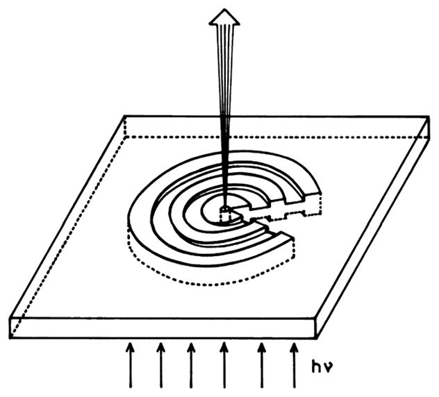
Directional emission from a fluorophore on a metal film with open concentric rings. Adapted from [140].
These optical transmission phenomena can be used with the properties of radiating plasmons to design novel fluorescence devices which both serve as the excitation filter and, more importantly, focus the emission in the desired direction and pattern. Using the concept that if a plasmon can radiate it will, fluorophores could be placed on either side of the films shown in Figs. 23 and 24. Depending on the geometry of the film and the optical constants of all the materials, fluorophores on or near the metal will transfer to the plasmons, which in turn will radiate according to electromagnetic theory.
Finally, we note that it is possible to use metallic structures to control plasmon transport across surfaces or through nanostructures [141,142]. In the previous sections we discussed the need for a prism to allow plasmons to radiate away from the surface. The converse is also true. If wavevector matching is not possible then the plasmons are trapped on the metal surface and cannot radiate. Depending on the metal and wavelength the migration distances can be substantial, up to 10 μm for silver for 1500-nm light and up to 500 μm for aluminum for 500-nm light [143,144]. Hence the emission from fluorophores in a large area of the sample can potentially be harvested and collected in an area where wavevector matching can occur, such as near a periodic grating. The periodic structure need not be the metal itself but can be a periodic dielectric structure which is placed on the metal surface [145].
An impressive example of plasmon transport is shown in Fig. 25 [146]. Theoretical calculations are shown for a line of about 40 silver nanoparticles. The first silver particle is assumed to be illuminated with 488-nm light. The scattered intensity decreases less than 100-fold at the 40th particle. The energy can be transported about 1000 nm (1 μm) with only a 10-fold loss in intensity. This calculation has many implications for plasmonic technology because methods to fabricate chains of colloids are appearing [147–149].
Fig. 25.
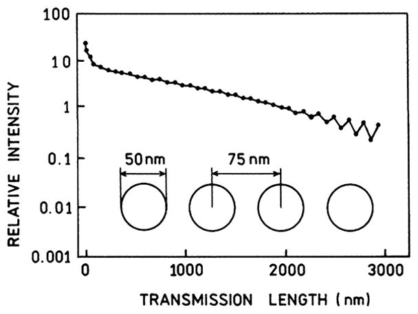
Plasmon transport (488 nm) along a line of 25-nm-radius silver shell particles, spaced 75 nm apart center to center distance. The silver shells had a dielectric interior. From [146].
Another impressive example of plasmon transport is shown in Fig. 26 [150]. The sample would be below a metal film with nanoholes or perhaps within the nanoholes themselves. It was found that quantum dots near individual holes could be excited if the polarization of the incident field was directed toward one of the holes using a near-field scanning optical microscopy (NSOM) tip. Alternatively the energy could be transported to the hole by a chain of colloids of the type shown in Fig. 25. Plasmon transport has been observed over micrometer distances through continuous nanowires [151,152]. One can readily imagine similar configurations using a NSOM tip or light source to irradiate one end of a nanowire or the use of a chain of colloids to excite a fluorophore at the distal end of the structure. Additionally, there has been progress in the fabrication of metallic nanostructures with a wide variety of spectral properties [153–155]. It appears that plasmon technology can be adopted for use with sensing assays which transport plasmon-coupled energy to be detected or radiated at a different location on the sensing assay.
Fig. 26.
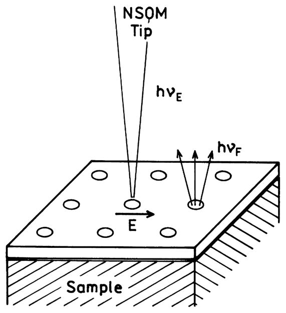
Selective excitation near nanoholes in a metal film. Adapted from [150].
In closing we believe that the rational design of metallic structures which couple with fluorophore and efficiently radiate the energy will provide the basis for a new generation of nano-optical sensing devices.
Conclusion
The results described above suggest a new way of thinking about excited fluorophores near metallic structures. It appears that metal-enhanced fluorescence is due to plasmon emission from plasmons created by the excited fluorophores. The spectral distribution of the plasmon emission is the same as that of the excited fluorophore. The metal structures appear to radiate the energy faster than the fluorophores themselves. In a sense, the fluorophores provide a Stokes’ shift to the metal particles, which otherwise would radiate (scatter) at the incident wavelength. The radiating plasmon model provides a rational approach for the use of metallic structures to collect, manipulate, and direct the energy from excited-state fluorophores. The ability provides numerous opportunities for the applications of fluorescence to chemical and medical analysis. The RP model is consistent with a wide range of experimental results, but to the best of our knowledge there has not been an explicit experimental verification of this concept. Studies to test the RP model are currently underway in this laboratory.
Acknowledgments
This work was supported by the National Center for Research Resources, RR-08119, and the National Institute of Biomedical Imaging and Bioengineering, EB-00682 and EB-00981.
Footnotes
Abbreviations used: LSWs, lossy surface waves; MEF, metal-enhanced fluorescence; RP, radiating plasmon; SIF, silver island films; SP(R), surface-plasmon (resonance); TIR, total internal reflection; SPCE, surface plasmon-coupled emission; NRP, nonradiative plasmon; NSOM, near-field scanning optical microscopy.
References
- 1.Drexhage KH. Influence of a dielectric interface on fluorescence decay time. J Luminesc. 1970;1.2:693–701. [Google Scholar]
- 2.Drexhage KH. In: Progress in Optics XII. Wolf E, editor. North-Holland; Amsterdam: 1974. p. 165. [Google Scholar]
- 3.Ford GW, Weber WH. Electromagnetic effects on a molecule at a metal surface. Surface Sci. 1981;109:451–481. [Google Scholar]
- 4.Korzeniewski GE, Maniv T, Metiu H. Electrodynamics at metal surfaces. IV. The electric fields caused by the polarization of a metal surface by an oscillating dipole. J Chem Phys. 1982;76(3):1564–1573. [Google Scholar]
- 5.Barnes WL. Topical review. Fluorescence near interfaces: the role of photonic mode density. J Mod Opt. 1998;45(4):661–699. [Google Scholar]
- 6.Sipe JE. The dipole antenna problem in surface physics: a new approach. Surface Sci. 1981;105:489–504. [Google Scholar]
- 7.Persson BNJ. Theory of the damping of excited molecules located above a metal surface. J Phys. 1978;C 11:4251–4269. [Google Scholar]
- 8.Chance RR, Prock A, Silbey R. Lifetime of an emitting molecule near a partially reflecting surface. J Chem Phys. 1974;60(7):2744–2748. [Google Scholar]
- 9.Tews KH. On the variation of luminescence lifetimes. The approximations of the approximative methods. J Luminesc. 1974;9:223–239. [Google Scholar]
- 10.Gersten J, Nitzan A. Spectroscopic properties of molecules interacting with small dielectric particles. J Chem Phys. 1981;75(3):1139–1152. [Google Scholar]
- 11.Ruppin R. Decay of an excited molecule near a small metal sphere. J Chem Phys. 1982;76(4):1681–1684. [Google Scholar]
- 12.Das PC, Puri A. Energy flow and fluorescence near a small metal particle. Phys Rev B. 2002;65:155416/1–155416/8. [Google Scholar]
- 13.Adams A, Rendell RW, Garnett RW, Hansma PK, Metiu H. Effect of metal film thickness on surface-atom coupling. Opt Commun. 1980;34(3):417–420. [Google Scholar]
- 14.Sokolov K, Chumanov G, Cotton TM. Enhancement of molecular fluorescence near the surface of colloidal metal films. Anal Chem. 1998;70:3898–3905. doi: 10.1021/ac9712310. [DOI] [PubMed] [Google Scholar]
- 15.Tarcha PJ, DeSaja-Gonzalez J, Rodriguez-Llorente S, Aroca R. Surface-enhanced fluorescence on SiO2 - coated silver island films. Appl Spectrosc. 1999;53(1):43–48. [Google Scholar]
- 16.DeSaja-Gonzalez J, Aroca R, Nagao Y, DeSaja JA. Surface-enhanced fluorescence and SERRS spectra of N-octadecyl-3,4:9,10- perylenetetracarboxylic monoanhydride on silver island films. Spectrochim Acta A. 1997;53:173–181. [Google Scholar]
- 17.Chance RR, Prock A, Silbey R. Molecular fluorescence and energy transfer near interfaces. Adv Chem Phys. 1973;37:1–65. [Google Scholar]
- 18.Ford GW, Weber WH. Electromagnetic interactions of molecules with metal surfaces. Phys Rep. 1984;113(4):195–287. [Google Scholar]
- 19.Moskovits M. Surface-enhanced spectroscopy. Rev Mod Phys. 1985;57(3):783–826. [Google Scholar]
- 20.Kummerlen J, Leitner A, Brunner H, Aussenegg FR, Wokaun A. Enhanced dye fluorescence over silver island films: analysis of the distance dependence. Mol Phys. 1993;80(5):1031–1046. [Google Scholar]
- 21.Metiu H. Surface enhanced spectroscopy. Surface Sci. 1984;17:153–320. [Google Scholar]
- 22.Lakowicz JR. Radiative decay engineering: biophysical and biomedical applications. Anal Biochem. 2001;298:1–24. doi: 10.1006/abio.2001.5377. [DOI] [PMC free article] [PubMed] [Google Scholar]
- 23.Lakowicz JR. Radiative decay engineering 3. Surface plasmon-coupled directional emission. Anal Biochem. 2004;324:153–169. doi: 10.1016/j.ab.2003.09.039. [DOI] [PMC free article] [PubMed] [Google Scholar]
- 24.Lakowicz JR, Shen Y, D’Auria S, Malicka J, Fang J, Gryczynski Z, Gryczynski I. Radiative decay engineering. 2. Effects of silver island films on fluorescence intensity, lifetimes and resonance energy transfer. Anal Biochem. 2002;301:261–277. doi: 10.1006/abio.2001.5503. [DOI] [PMC free article] [PubMed] [Google Scholar]
- 25.Malicka J, Gryczynski I, Fang J, Lakowicz JR. Fluorescence spectral properties of cyanine dye-labeled DNA oligomers on surfaces coated with silver particles. Anal Biochem. 2003;317:136–146. doi: 10.1016/S0003-2697(03)00005-8. [DOI] [PMC free article] [PubMed] [Google Scholar]
- 26.Malicka J, Gryczynski I, Maliwal BP, Fang J, Lakowicz JR. Fluorescence spectral properties of cyanine dye labeled DNA near metallic silver particles. Biopolymers. 2003;72:96–104. doi: 10.1002/bip.10301. [DOI] [PubMed] [Google Scholar]
- 27.Maliwal BP, Malicka J, Gryczynski I, Gryczynski Z, Lakowicz JR. Fluorescence properties of labeled proteins near silver colloid surfaces. Biopolymers. 2003;70:585–594. doi: 10.1002/bip.10501. [DOI] [PMC free article] [PubMed] [Google Scholar]
- 28.Geddes CD, Cao H, Gryczynski I, Gryczynski Z, Fang J, Lakowicz JR. Metal-enhanced fluorescence (MEF) due to silver colloids on a planar surface: potential applications of indocyanine green to in vivo imaging. J Phys Chem A. 2003;107:3443–3449. doi: 10.1021/jp022040q. [DOI] [PMC free article] [PubMed] [Google Scholar]
- 29.Parfenov A, Gryczynski I, Malicka J, Geddes CD, Lakowicz JR. Enhanced fluorescence from fluorophores on fractal silver surfaces. J Phys Chem B. 2003;107:8829–8833. doi: 10.1021/jp022660r. [DOI] [PMC free article] [PubMed] [Google Scholar]
- 30.Gryczynski I, Malicka J, Holder E, DiCesare N, Lakowicz JR. Effects of metallic silver particles on the emission properties of [Ru(bpy)3]2+ Chem Phys Lett. 2002;372:409–414. doi: 10.1016/S0009-2614(03)00420-2. [DOI] [PMC free article] [PubMed] [Google Scholar]
- 31.Lakowicz JR, Maliwal BP, Malicka J, Gryczynski Z, Gryczynski I. Effects of silver island films on the luminescent intensity and decay times of lanthanide chelates. J Fluoresc. 2002;12(314):431–437. doi: 10.1023/A:1021318127519. [DOI] [PMC free article] [PubMed] [Google Scholar]
- 32.Strickler SJ, ABerg R. Relationship between absorption intensity and fluorescence lifetime of molecules. J Chem Phys. 1962;37(4):814–822. [Google Scholar]
- 33.Toptygin D. Effects of the solvent refractive index and its dispersion on the radiative decay rate and extinction coefficient of a fluorescent solute. J Fluoresc. 2003;13(3):201–219. [Google Scholar]
- 34.Toptygin D, Savtchenko RS, Meadow ND, Roseman S, Brand L. Effect of the solvent refractive index on the excited-state lifetime of a single tryptophan residue in a protein. J Phys Chem B. 2002;106:3724–3734. [Google Scholar]
- 35.Krishna MMG, Periasamy N. Orientational distribution of linear dye molecules in bilayer membranes. Chem Phys Lett. 1998;298:359–367. [Google Scholar]
- 36.Gryczynski I, Malicka J, Gryczynski Z, Lakowicz JR. Radiative decay engineering 4. Experimental studies of surface plasmon-coupled directional emission. Anal Biochem. 2004;324:170–182. doi: 10.1016/j.ab.2003.09.036. [DOI] [PMC free article] [PubMed] [Google Scholar]
- 37.Lakowicz JR, Malicka J, Gryczynski I, Gryczynski Z. Directional surface plasmon-coupled emission: a new method for high sensitivity detection. Biochem Biophys Res Commun. 2003;307:435–439. doi: 10.1016/S0006-291X(03)01214-2. [DOI] [PMC free article] [PubMed] [Google Scholar]
- 38.Malicka J, Gryczynski I, Gryczynski Z, Lakowicz JR. DNA hybridization using surface plasmon-coupled emission. Anal Chem. 2003;75:6629–6633. doi: 10.1021/ac034881e. [DOI] [PMC free article] [PubMed] [Google Scholar]
- 39.Gryczynski I, Malicka J, Gryczynski Z, Lakowicz JR. Surface plasmon-coupled emission using gold films. J Phys Chem B. 2004;108:12568–12574. doi: 10.1021/jp040221h. [DOI] [PMC free article] [PubMed] [Google Scholar]
- 40.Gryczynski I, Malicka J, Gryczynski Z, Nowaczyk K, Lakowicz JR. Ultraviolet surface plasmon-coupled emission using thin aluminum films. Anal Chem. 2004;76:4076–4081. doi: 10.1021/ac040004c. [DOI] [PMC free article] [PubMed] [Google Scholar]
- 41.Zhang J, Gryczynski Z, Lakowicz JR. First observation of surface plasmon-coupled electrochemiluminescence. Chem Phys Lett. 2004;393:483–487. doi: 10.1016/j.cplett.2004.06.050. [DOI] [PMC free article] [PubMed] [Google Scholar]
- 42.Huang T, Murray RW. Quenching of [Ru(bpy)3]2+ fluorescence by binding to Au nanoparticles. Langmuir. 2002;18:7077–7081. [Google Scholar]
- 43.Fan C, Wang S, Hong JW, Bazan GC, Plaxco KW, Heeger AJ. Beyond superquenching: hyper-efficient energy transfer from conjugated polymers to gold nanoparticles. Proc Natl Acad Sci USA. 2003;100(11):6297–6301. doi: 10.1073/pnas.1132025100. [DOI] [PMC free article] [PubMed] [Google Scholar]
- 44.Dulkeith E, Morteani AC, Niedereichholz T, Klar TA, Feldmann J, Levi SA, van Veggel FCJM, Reinhoudt DN, Moller M, Gittins DI. Fluorescence quenching of dye molecules near gold nanoparticles: radiative and nonradiative effects. Phys Rev Lett. 2002;89(20):203002-1–203002-4. doi: 10.1103/PhysRevLett.89.203002. [DOI] [PubMed] [Google Scholar]
- 45.Du H, Disney MD, Miller BL, Krauss TD. Hybridization-based unquenching of DNA hairpins on Au surfaces: prototypical “molecular beacon” biosensors. J Am Chem Soc. 2003;125:4012–4013. doi: 10.1021/ja0290781. [DOI] [PubMed] [Google Scholar]
- 46.Dubertret B, Calame M, Libchaber AJ. Single-mismatch detection using gold-quenched fluorescent oligonucleotides. Nat Biotechnol. 2001;19:365–370. doi: 10.1038/86762. [DOI] [PubMed] [Google Scholar]
- 47.Garoff S, Weitz DA, Alvarez MS, Gersten JI. Electrodynamics at rough metal surfaces: photochemistry and luminescence of adsorbates near metal-island films. J Chem Phys. 1984;81(11):5189–5200. [Google Scholar]
- 48.Cnossen G, Drabe KE, Wiersma DA. Fluorescence properties of submonolayers of rhodamine 6G in front of a mirror. J Chem Phys. 1993;98(7):5276–5280. [Google Scholar]
- 49.Pal T, Jana NR, Sau T. Nanoparticle induced fluorescence quenching. Radiat Phys Chem. 1997;49(1):127–130. [Google Scholar]
- 50.Junior AM, Moises de Oliveira HP, Gehlen MH. Preparation of silver nanoprisms using poly(N-vinyl-2-pyrrolidone) as a colloid-stabilizing agent and the effect of silver nanoparticles on the photophysical properties of cationic dyes. Photochem Photobiol Sci. 2003;2:921–925. doi: 10.1039/b302943c. [DOI] [PubMed] [Google Scholar]
- 51.De S, Pal A, Jana NR, Pal T. Anion effect in linear silver nanoparticle aggregation as evidenced by efficient fluorescence quenching and SERS enhancement. J Photochem Photobiol A. 2000;131:111–123. [Google Scholar]
- 52.Malicka J, Gryczynski I, Gryczynski Z, Lakowicz JR. Effects of fluorophore-to-silver distance on the emission of cyanine-dye-labeled oligonucleotides. Anal Biochem. 2003;315:57–66. doi: 10.1016/S0003-2697(02)00702-9. [DOI] [PMC free article] [PubMed] [Google Scholar]
- 53.Liebsch A. Electronic Excitations at Metal Surfaces. Plenum Press; New York: 1997. p. 336. [Google Scholar]
- 54.Raether H. Surface plasma oscillations and their applications. In: Hass G, Francombe MH, Hoffman RW, editors. Physics of Thin Films. Vol. 9. Academic Press; New York: 1977. pp. 145–261.pp. 316 [Google Scholar]
- 55.Sambles JR, Bradbery GW, Yang F. Optical excitation of surface plasmons: an introduction. Contemp Phys. 1991;32(3):173–183. [Google Scholar]
- 56.Zayats AV, Smolyaninov II. Near-field photonics: surface plasmon polaritons and localized surface plasmons. J Opt A. 2003;5:S16–S50. [Google Scholar]
- 57.Welford K. Surface plasmon-polaritons and their uses. Opt Quantum Electron. 1991;23:1–27. [Google Scholar]
- 58.Link S, El-Sayed MA. Shape and size dependence of radiative, non-radiative and photothermal properties of gold nanocrystals. Int Rev Phys Chem. 2000;19(3):409–453. [Google Scholar]
- 59.Kerker M. The optics of colloidal silver: something old and something new. J Colloid Interface Sci. 1985;105(2):297–314. [Google Scholar]
- 60.Inacker O, Kuhn H, Bucher H, Meyer H, Tews KH. Monolayer assembling technique used to determine the multipole nature of the phosphorescence of a dye molecule. Chem Phys Lett. 1970;7(2):213–218. [Google Scholar]
- 61.Griffiths DJ. Introduction to Electrodynamics. Prentice Hall; New Jersey: 1999. p. 576. [Google Scholar]
- 62.Born M, Wolf E. Principles of Optics: Electromagnetic Theory of Propagation, Interference and Diffraction of Light. Pergamon Press; New York: 1980. p. 808. [Google Scholar]
- 63.Klein MV. Optics. Wiley; New York: 1970. p. 647. [Google Scholar]
- 64.Forstmann F, Gerhardts RR. Springer Tracts In Modern Physics. Vol. 109. Springer-Verlag; New York: 1986. Metal optics near the plasma frequency; p. 132. [Google Scholar]
- 65.Agranovich VM, Mills DL, editors. Surface Polaritons: Electromagnetic Waves at Surfaces and Interfaces. North-Holland Pub. Co; New York: 1982. p. 716. [Google Scholar]
- 66.Boardman AD. Electromagnetic Surface Modes. Wiley; New York: 1982. p. 775. [Google Scholar]
- 67.Raether H. Surface Plasmons on Smooth and Rough Surfaces and on Gratings. Springer-Verlag; New York: 1988. p. 136. [Google Scholar]
- 68.Wei A. Nanoparticles: Building Blocks for Nanotechnology. Vol. 7. Kluwer Academic/Plenum Publishers; New York: 2004. Plasmonic nanomaterials. Enhanced optical properties from metal nanoparticles and their ensembles; pp. 173–200.pp. 284 [Google Scholar]
- 69.Scharte M, Porath R, Ohms T, Aeschlimann, Krenn JR, Ditlbacher H, Aussenegg FR, Liebsch A. Do Mie plasmons have a longer lifetime on resonance than off resonance? Appl Phys B. 2001;73:305–310. [Google Scholar]
- 70.Campion A, Gallo AR, Harris CB, Robota HJ, Whitmore PM. Electronic energy transfer to metal surfaces: a test of classical image dipole theory at short distances. Chem Phys Lett. 1980;73(3):447–450. [Google Scholar]
- 71.Vaubel G, Baessler H, Möbius D. Reaction of singlet excitons at an anthracene/metal interface: energy transfer. Chem Phys Lett. 1971;10(3):334–336. [Google Scholar]
- 72.Inacker O, Kuhn H. Energy transfer from dye to specific singlet or triplet energy acceptors in monolayer assemblies. Chem Phys Lett. 1974;27(3):317–321. [Google Scholar]
- 73.Adams A, Rendell RW, Garnett RW, Hansma PK. Effect of metal film thickness on surface-atom coupling. Opt Commun. 1980;34(3):417–420.65. [Google Scholar]
- 74.Kreirib U, Vollmer M. Optical Properties of Metal Clusters. Springer; Berlin: 1995. p. 532. [Google Scholar]
- 75.Feldheim DL, Foss CA. Metal Nanoparticles. Synthesis, Characterization and Applications. Marcel Dekker Inc; New York: 2002. p. 338. [Google Scholar]
- 76.Kerker M, Blatchford CG. Elastic scattering, absorption, and surface-enhanced Raman scattering by concentric spheres comprised of a metallic and a dielectric region. Phys Rev B. 1982;26(8):4052–4063. [Google Scholar]
- 77.Yguerabide J, Yguerabide E. Light-scattering submicroscopic-particles as highly fluorescent analogs and their use as tracer labels in clinical and biological applications: I. Theory. Anal Biochem. 1998;262:137–156. doi: 10.1006/abio.1998.2759. [DOI] [PubMed] [Google Scholar]
- 78.Yguerabide J, Yguerabide E. Light-scattering submicroscopic-particles as highly fluorescent analogs and their use as tracer labels in clinical and biological applications: II. Experimental characterization. Anal Biochem. 1998;262:157–176. doi: 10.1006/abio.1998.2760. [DOI] [PubMed] [Google Scholar]
- 79.Chance RR, Miller AH, Prock A, Silbey R. Fluorescence and energy transfer near interfaces: the complete and quantitative description of the Eu3+/mirror systems. J Chem Phys. 1975;63:1589–1595. [Google Scholar]
- 80.Kuhn H. Classical aspects of energy transfer in molecular systems. J Chem Phys. 1970;53(1):101–108. [Google Scholar]
- 81.Maliwal BP, Gryczynski Z, Lakowicz JR. Long-wavelength long-lifetime luminophores. Anal Chem. 2001;73:4277–4285. doi: 10.1021/ac0101050. [DOI] [PMC free article] [PubMed] [Google Scholar]
- 82.Kang JS, Piszczek G, Lakowicz JR. Enhanced emission induced by FRET from a long-lifetime, low quantum yield donor to a long-wavelength, high quantum yield acceptor. J Fluoresc. 2002;12(1):97–103. doi: 10.1023/A:1015375622992. [DOI] [PMC free article] [PubMed] [Google Scholar]
- 83.Andersen PC, Rowlen KL. Brilliant optical properties of nanometric noble metal spheres, rods, and aperture arrays. Appl Spectrosc. 2002;56(5):124A–135A. [Google Scholar]
- 84.Messinger BJ, Ulrich von Raben K, Chang RK, Barber PW. Local fields at the surface of noble-metal microspheres. Phys Rev B. 1981;24(2):649–657. [Google Scholar]
- 85.Hao E, Schatz GC. Electromagnetic fields around silver nanoparticles and dimers. J Chem Phys. 2004;120(1):357–366. doi: 10.1063/1.1629280. [DOI] [PubMed] [Google Scholar]
- 86.Kreibig U, Genzel L. Optical absorption of small metallic particles. Surface Sci. 1983;156:678–700. [Google Scholar]
- 87.Jensen T, Kelly L, Lazarides A, Schatz GC. Electrodynamics of noble metal nanoparticles and nonoparticle clusters. J Cluster Sci. 1999;10(2):295–317. [Google Scholar]
- 88.Su K-H, Wei Q-H, Zhang X, Mock JJ, Smith DR, Schultz S. Interparticle coupling effects on plasmon resonances of nanogold particles. Nano Lett. 2003;3(8):1087–1090. [Google Scholar]
- 89.Rechberger W, Hohenau A, Leitner A, Krenn JR, Lamprecht B, Aussenegg FR. Optical properties of two interacting gold nanoparticles. Opt Commun. 2003;220:137–141. [Google Scholar]
- 90.Blatchford CG, Campbell JR, Creighton JA. Plasma resonance-enhanced raman scattering by adsorbates on gold colloids: the effects if aggregation. Surface Sci. 1982;120:435–455. [Google Scholar]
- 91.Kim NT, Rosenzweig Z. Development of an aggregation-based immunoassay for anti-protein A using gold nanoparticles. Anal Chem. 2002;74:1624–1628. doi: 10.1021/ac011127p. [DOI] [PubMed] [Google Scholar]
- 92.Hirsch LR, Jackson JB, Lee A, Halas NJ, West JL. A whole blood immunoassay using gold nanoshells. Anal Chem. 2003;75:2377–2381. doi: 10.1021/ac0262210. [DOI] [PubMed] [Google Scholar]
- 93.Elghanian R, Storhoff JJ, Mucic RC, Letsinger RL, Mirkin CA. Selective colorimetric detection of polynucleotides based on the distance-dependent optical properties of gold nanoparticles. Science. 1997;277:1078–1081. doi: 10.1126/science.277.5329.1078. [DOI] [PubMed] [Google Scholar]
- 94.Sastry M, Lala N, Patil V, Chavan SP, Chittiboyina AG. Optical absorption study of the biotin–avidin interaction on colloidal silver and gold particles. Langmuir. 1998;14:4138–4142. [Google Scholar]
- 95.Kim Y, Johnson RC, Hupp JT. Gold nanoparticle-based sensing of “spectroscopically silent” heavy metal ions. Nano Lett. 2001;1(4):165–167. [Google Scholar]
- 96.Jin R, Wu G, Li Z, Mirkin CA, Schatz GC. What controls the melting properties of DNA-linked gold nanoparticle assemblies? J Am Chem Soc. 2003;125:1643–1654. doi: 10.1021/ja021096v. [DOI] [PubMed] [Google Scholar]
- 97.Storhoff JJ, Elghanian R, Mucic RC, Mirkin CA, Letsinger RL. One-pot colorimetric differentiation of polynucleotides with single base imperfections using gold nanoparticle probes. J Am Chem Soc. 1998;120:1959–1964. [Google Scholar]
- 98.Lazarides AA, Schatz GC. DNA-linked metal nanosphere materials: Structural basis for the optical properties. J Phys Chem. 2000;104:460–467. [Google Scholar]
- 99.Jensen T, Kelly L, Lazarides A, Schatz GC. Electrodynamics of noble metal nanoparticles and nanoparticle clusters. J Cluster Sci. 1999;10(2):295–317. [Google Scholar]
- 100.Haynes CL, McFarland AD, Zhao L, Van Duyne RP, Schatz GC, Gunnarsson L, Prikulis J, Kasemo B, Kail M. Nanoparticle optics: the importance of radiative dipole coupling in two-dimensional nanoparticle arrays. J Phys Chem B. 2003;107:7337–7342. [Google Scholar]
- 101.Zhao L, Kelly KL, Schatz GC. The extinction spectra of silver nanoparticle arrays: influence of array structure on plasmon resonance wavelength and width. J Phys Chem B. 2003;107:7343–7350. [Google Scholar]
- 102.Sosa IO, Noguez C, Barrera RG. Optical properties of metal nanoparticles with arbitrary shapes. J Phys Chem B. 2003;107:6269–6275. [Google Scholar]
- 103.Zhang J, Han B, Liu M, Liu D, Dong Z, Liu J, Li D. Ultrasonication-induced formation of silver nanofibers in reverse micelles and small-angle x-ray scattering studies. J Phys Chem B. 2003;107:3679–3683. [Google Scholar]
- 104.Kim F, Song JH, Yang P. Photochemical synthesis of gold nanorods. J Am Chem Soc. 2002;124:14316–14317. doi: 10.1021/ja028110o. [DOI] [PubMed] [Google Scholar]
- 105.Taub N, Krichevski O, Markovich G. Growth of gold nanorods on surfaces. J Phys Chem B. 2003;107:11579–11582. [Google Scholar]
- 106.Jana NR, Gearheart L, Murphy CJ. Wet chemical synthesis of high aspect ratio cylindrical gold nanorods. J Phys Chem B. 2001;105:40656–40667. [Google Scholar]
- 107.Chen S, Carroll DL. Synthesis and characterization of truncated triangular silver nanoplates. Nano Lett. 2002;2(9):1003–1007. [Google Scholar]
- 108.Maillard M, Giorgio S, Pileni MP. Tuning the size of silver nanodisks with similar aspect ratios: synthesis and optical properties. J Phys Chem B. 2003;107:2466–2470. [Google Scholar]
- 109.Chen S, Fan Z, Carroll DL. Silver nanodisks: synthesis, characterization, and self-assembly. J Phys Chem. 2002;106(42):10777–10781. [Google Scholar]
- 110.Pham T, Jackson JB, Halas NJ, Lee TR. Preparation and characterization of gold nanoshells coated with self-assembled monolayers. Langmuir. 2002;18:4915–4920. [Google Scholar]
- 111.Sun Y, Xia Y. Increased sensitivity of surface plasmon resonance of gold nanoshells compared to that of gold solid colloids in response to environmental changes. Anal Chem. 2002;74:5297–5305. doi: 10.1021/ac0258352. [DOI] [PubMed] [Google Scholar]
- 112.Chen MMY, Katz A. Synthesis and characterization of gold-silica nanoparticles incorporating a mercaptosilane core-shell interface. Langmuir. 2002;18:8566–8572. [Google Scholar]
- 113.Underwood S, Mulvaney P. Effect of the solution refractive index on the color of gold colloids. Langmuir. 1994;10:3427–3430. [Google Scholar]
- 114.Weber WH, Eagen CF. Energy transfer from an excited dye molecule to the surface plasmons of an adjacent metal. Opt Lett. 1979;4(8):236–238. doi: 10.1364/ol.4.000236. [DOI] [PubMed] [Google Scholar]
- 115.Aravind PK, Metiu H. The effects of the interaction between resonances in the electromagnetic response of a sphere-plane structure; applications to surface enhanced spectroscopy. Surface Sci. 1983;124:506–528. [Google Scholar]
- 116.Hayashi S. SERS on random rough silver surfaces: evidence of surface plasmon excitation and the enhancement factor for copper phthalocyanine. Surface Sci. 1985;158:229–237. [Google Scholar]
- 117.Hayashi S. Spectroscopy of gap modes in metal particle-surface systems. In: Kawata S, editor. Near-field Optics and Surface Plasmon Polaritons, Topics Appl Phys. Vol. 81. 2001. pp. 71–95. [Google Scholar]
- 118.Hayashi S, Kume T, Amano T, Yamamoto K. A new method of surface plasmon excitation mediated by metallic nanoparticles. Jpn J Appl Phys. 1996;35:L331–L334. [Google Scholar]
- 119.Kume T, Hayashi S, Yamamoto K. A new method of surface plasmon excitation using metallic fine particles. Mat Sci Eng. 1996;A217/218:171–175. [Google Scholar]
- 120.Aoki Y, Kato K, Shinbo K, Kaneko F, Wakamatsu T. Scattered light due to excited surface plasmon in arachidic acid LB ultrathin films on silver thin films. Thin Solid Films. 1998;327/329:360–363. [Google Scholar]
- 121.Arias J, Aravind PK, Metiu H. The fluorescence lifetime of a molecule emitting near a surface with small, random roughness. Chem Phys Lett. 1982;85(4):404–408. [Google Scholar]
- 122.Leung PT, George TF. Energy-transfer theory for the classical decay rates of molecules at rough metallic surfaces. Phys Rev B. 1987;36(9):4664–4671. doi: 10.1103/physrevb.36.4664. [DOI] [PubMed] [Google Scholar]
- 123.Fontana E, Pantell RH. Characterization of multilayer rough surfaces by use of surface-plasmon spectroscopy. Phys Rev B. 1988;37(7):3164–3182. doi: 10.1103/physrevb.37.3164. [DOI] [PubMed] [Google Scholar]
- 124.Kitson SC, Barnes WL, Sambles JR. Photoluminescence from dye molecules on silver gratings. Opt Commun. 1996;122:147–154. [Google Scholar]
- 125.Kitson SC, Barnes WL, Sambles JR, Cotter NPK. Excitation of molecular fluorescence via surface plasmon polaritons. J Mod Opt. 1996;43(3):573–582. [Google Scholar]
- 126.Wasey JAE, Safonov A, Jory MJ, Samuel IDW, Barnes WL. Controlling the optical emission from the polymer MEH-PPV using corrugated thin films. Eur Phys J AP. 2002;18:89–97. [Google Scholar]
- 127.Kalkman J, Strohhofer C, Gralak B, Polman A. Surface plasmon polariton modified emission of erbium in a metallo-dielectric grating. Appl Phys Lett. 2003;83(1):30–32. [Google Scholar]
- 128.Lemarchand F, Rigneault H. Light emission from europium chelates located in crossed grating structures. J Opt A. 2002;4:S115–S118. [Google Scholar]
- 129.Kitson SC, Barnes WL, Sambles JR. Surface-plasmon energy gaps and photoluminescence. Phys Rev B. 1995;52(15):11441–11445. doi: 10.1103/physrevb.52.11441. [DOI] [PubMed] [Google Scholar]
- 130.Gruhlke RW, Holland WR, Hall DG. Surface-plasmon cross coupling in molecular fluorescence near a corrugated thin metal film. Phys Rev Lett. 1986;56(26):2838–2841. doi: 10.1103/PhysRevLett.56.2838. [DOI] [PubMed] [Google Scholar]
- 131.Gruhlke RW, Hall DG. Transmission of molecular fluorescence through a thin metal film by surface plasmons. Appl Phys Lett. 1988;53(12):1041–1042. [Google Scholar]
- 132.Gifford DK, Hall DG. Emission through one of two metal electrodes of an organic light-emitting diode via surface-plasmon cross coupling. Appl Phys Lett. 2002;81(23):4315–4317. [Google Scholar]
- 133.Gifford DK, Hall DG. Extraordinary transmission of organic photoluminescence through an otherwise opaque metal layer via surface plasmon cross coupling. Appl Phys Lett. 2002;80(20):3679–3681. [Google Scholar]
- 134.Ebbesen TW, Lezec HJ, Ghaemi HF, Thio T, Wolff PA. Extraordinary optical transmission through subwavelength hole arrays. Nature. 1998;381:667–669. [Google Scholar]
- 135.Bonod N, Enoch S, Li L, Popov E, Neviere M. Resonant optical transmission through thin metallic films with and without holes. Opt Express. 2003;11(5):482–490. doi: 10.1364/oe.11.000482. [DOI] [PubMed] [Google Scholar]
- 136.Zayats AV, Salomon L, De Fornel F. How light gets through periodically nanostructured metal films: a role of surface polaritonic crystals. J Microsc. 2003;210(3):344–349. doi: 10.1046/j.1365-2818.2003.01161.x. [DOI] [PubMed] [Google Scholar]
- 137.Thio T, Lezec HJ, Ebbesen TW, Pellerin KM, Lewen GD, Nahata A, Linke RA. Giant optical transmission of subwavelength apertures: physics and applications. Nanotechnology. 2002;13:429–432. [Google Scholar]
- 138.Martin-Moreno L, Garcia-Vidal FJ, Lezec HJ, Degiron A, Ebbesen TW. Theory of highly directional emission from a single subwavelength aperture surrounded by surface corrugations. Phys Rev Lett. 2003;90(16):167401.1–167401.4. doi: 10.1103/PhysRevLett.90.167401. [DOI] [PubMed] [Google Scholar]
- 139.Garcia-Vidal FJ, Lezec HJ, Ebbesen TW, Martin-Moreno L. Multiple paths to enhance optical transmission through a single subwavelength slit. Phys Rev Lett. 2003;90(21):213901-1–213901-4. doi: 10.1103/PhysRevLett.90.213901. [DOI] [PubMed] [Google Scholar]
- 140.Lezec HJ, Degiron A, Devaux E, Linke RA, Martin-Moreno L, Garcia-Vidal FJ, Ebbesen TW. Beaming light from a subwavelength aperture. Science. 2002;297:820–822. doi: 10.1126/science.1071895. [DOI] [PubMed] [Google Scholar]
- 141.Ditlbacher H, Krenn JR, Felidj N, Lamprecht B, Schider G, Salerno M, Leitner A, Aussenegg FR. Fluorescence imaging of surface plasmon fields. Appl Phys Lett. 2002;80(3):404–406. [Google Scholar]
- 142.Ditlbacher H, Krenn JR, Schider G, Leitner A, Aussenegg FR. Two-dimensional optics with surface plasmon polaritons. Appl Phys Lett. 2002;81(10):1762–1764. [Google Scholar]
- 143.Barnes WL, Dereux A, Ebbesen TW. Surface plasmon subwavelength optics. Nature. 2003;424:824–830. doi: 10.1038/nature01937. [DOI] [PubMed] [Google Scholar]
- 144.Lamprecht B, Krenn JR, Schider G, Dittlbacher H, Salerno M, Felidj N, Leitner A, Aussenegg FR, Weeber JC. Surface plasmon propagation in microscale metal stripes. Appl Phys Lett. 2001;79(1):51–53. [Google Scholar]
- 145.Park S, Lee G, Song SH, HOh C, Kim PS. Resonant coupling of surface plasmons to radiation modes by use of dielectric gratings. Opt Lett. 2003;28(20):1870–1871. doi: 10.1364/ol.28.001870. [DOI] [PubMed] [Google Scholar]
- 146.Quinten M, Leitner A, Krenn JR, Aussenegg FR. Electromagnetic energy transport via linear chains of silver nanoparticles. Opt Lett. 1998;23(17):1331–1333. doi: 10.1364/ol.23.001331. [DOI] [PubMed] [Google Scholar]
- 147.Keren K, Krueger M, Gilad R, Ben-Yoseph G, Sivan U, Braun E. Sequence-specific molecular lithography on single DNA molecules. Science. 2002;297:72–75. doi: 10.1126/science.1071247. [DOI] [PubMed] [Google Scholar]
- 148.Nakao H, Shiigi H, Yamamoto Y, Tokonami S, Nagaoka T, Sugiyama S, Ohtani T. Highly ordered assemblies of Au nanoparticles organized on DNA. Nano Lett. 2003;3(10):1391–1394. [Google Scholar]
- 149.Braun E, Eichen Y, Sivan U, Ben-Yoseph G. DNA-templated assembly and electrode attachment of a conducting silver wire. Nature. 1998;391:775–778. doi: 10.1038/35826. [DOI] [PubMed] [Google Scholar]
- 150.Brun M, Drezet A, Mariette H, Chevalier N, Woehl JC, Huant S. Remote optical addressing of single nano-objects. Europhys Lett. 2003;64(5):634–640. [Google Scholar]
- 151.Weeber J-C, Dereux A, Girard C. Plasmon polaritons of metallic nanowires for controlling submicron propagation of light. Phys Rev B. 1999;60(12):9061–9068. [Google Scholar]
- 152.Krenn JR, Lamprecht B, Ditlbacher H, Schider G, Salerno M, Leitner A, Aussenegg FR. Non-diffraction-limited light transport by gold nanowires. Europhys Lett. 2002;60(5):663–669. [Google Scholar]
- 153.Haynes CL, Van Duyne RP. Nanosphere lithography: a versatile nanofabrication tool for studies of size-dependent nanoparticle optics. J Phys Chem B. 2001;105:5599–5611. [Google Scholar]
- 154.Jensen TR, Malinsky MD, Haynes CL, Van Duyne RP. Nanosphere lithography: tunable localized surface plasmon resonance spectra of silver nanoparticles. J Phys Chem B. 2000;104:10549–10556. [Google Scholar]
- 155.Kuo CW, Shiu JY, Chen P, Somorjai GA. Fabrication of size-tunable large-area periodic silicon nanopillar arrays with sub-10-nm resolution. J Phys Chem B. 2003;107:9950–9953. [Google Scholar]