

Abstract
Electrospun nanofibers can be readily assembled into various types of scaffolds for applications in neural tissue engineering. The objective of this study is to examine and understand the unique patterns of neurite outgrowth from primary dorsal root ganglia (DRG) cultured on scaffolds of electrospun nanofibers having different orders, structures, and surface properties. We found that the neurites extended radially outward from the DRG main body without specific directionality when cultured on a nonwoven mat of randomly oriented nanofibers. In contrast, the neurites preferentially extended along the long axis of fiber when cultured on a parallel array of aligned nanofibers. When seeded at the border between regions of aligned and random nanofibers, the same DRG simultaneously expressed aligned and random neurite fields in response to the underlying nanofibers. When cultured on a double-layered scaffold where the nanofibers in each layer were aligned along a different direction, the neurites were found to be dependent on the fiber density in both layers. This bi-axial pattern clearly demonstrates that neurite outgrowth can be influenced by nanofibers in different layers of a scaffold, rather than the topmost layer only. Taken together, these results will provide valuable information pertaining to the design of nanofiber scaffolds for neuroregenerative applications, as well as the effects of topology on neurite outgrowth, growth cone guidance, and axonal regeneration.
Keywords: electrospun nanofibers, patterning, coating, neurite outgrowth, guidance
Structural and biomolecular patterns play an important role in the embryonic development of the nervous system. In building the intricate neural networks, axons must be precisely guided to the synaptic targets and various cell populations have to be spatially distributed into a specific pattern. The effectiveness of these two processes critically depends on the presence of patterned cues to guide neurite outgrowth. The cues can typically be divided into two main categories: chemical cues based on neurite attractive/repulsive molecules (e.g., netrins, slits, semaphorins, and ephrins),1 and physical cues that may include applied tension/stress, electrical polarization, magnetic field, and topography.2–5
The effects of topographic cues on neurite extension have been extensively investigated through the use of substrates containing microgrooves or microchannels of different depths and widths, typically generated using microlithography. Neurites have been demonstrated to grow parallel to a channel when the channel was 20–40 μm wide, but perpendicular to a channel when the width increased to the range of 40–60 μm.6 Also, neurites have been aligned perpendicular to shallow grooves of 1 μm in width and hundreds of nanometers in depth.7 In addition, neonatal rat DRG neurons have been cultured on poly(dimethyl siloxane) (PDMS) substrates patterned with grooves and coated with poly-L-lysine (PLL) and laminin, and it was shown that the neurites could extend across several adjacent grooves.8 Another recent study suggested that topography might play a critical role in axon formation and that trophic support, such as immobilized nerve growth factor (NGF), could enhance axon growth only after initiation.[9] Although soft lithographic techniques allow for the fabrication of topographical features with precise dimensions for investigating the role of topography in axonal growth at the micro- and nanoscale, PDMS has little value for translational research as it is not biodegradable.9
Electrospinning is an effective and widely utilized method for producing continuous fine fibers from polymer solutions or melts for a variety of applications.10–12 So far this technique has been successfully applied to more than 100 types of natural and synthetic polymers.13 Due to their small diameters and large surface areas, electrospun nanofibers can be employed to mimic the extracellular matrix (ECM) for cell attachment and nutrient transportation, and have been intensively investigated as scaffolds for various tissue engineering applications. In particular, aligned nanofibers are well-suited for neural tissue engineering as the anisotropic properties of aligned nanofibers may provide spatial guidance for neurite outgrowth and axonal elongation in vitro. For example, previous studies have shown that aligned nanofibers were better suited for culturing neural stem cells in vitro than scaffolds consisting of randomly oriented nanofibers.14 Other studies have also demonstrated that aligned nanofibers were able to direct neurite extension from cultured DRG and guide axonal growth or glia migration.15–17 In addition, one prior study showed that neurite outgrowth was significantly increased on aligned nanofibers immobilized with laminin relative to untreated samples.18 In all these studies, however, neurite extension was only examined for single-layered scaffolds that only contained either aligned or randomly oriented nanofibers. Given the intricate structure of a neural network, it will be interesting and significant to investigate neurite extension and axonal regeneration on more complex scaffolds such as single-layered scaffolds containing both aligned and disordered fibers with an interface between them, and bi-layered scaffolds comprised of nanofibers with different orders or orientations.
In the past, we and other groups have modified electrospinning to provide a simple and versatile method for generating two- and three-dimensional assemblies of nanofibers with well-defined and controllable orders, structures, and surface properties.11, 19–22 In the present study, we cultured embryonic chick DRG on some of these assemblies consisting of nanofibers electrospun from poly(ε-caprolactone) (PCL), a biocompatible and biodegradable polymer, and then examined the outgrowth of neurites in vitro. These studies not only provide a better understanding of neurite outgrowth, growth cone guidance, and axonal regeneration on nanofiber scaffolds, but also offer valuable information with regard to the design of new scaffolds for neuroregenerative applications.
RESULTS AND DISCUSSION
In our previous studies, we were able to generate uniaxially aligned fibers across the void gap of a metal frame and multi-layered fiber mats with controllable hierarchical structures by layer-by-layer stacking.11, 19–22 In the present work, scaffolds made of randomly oriented nanofibers were fabricated by directly depositing the electrospun fibers onto glass cover slips. Figure 1A shows a scanning electron microscopy (SEM) image of a typical sample of randomly oriented PCL nanofibers. Figure 1B shows the Fourier Fast Transfer (FFT) analysis, indicating that the nanofibers were randomly oriented because the pixel intensities (labeled with light blue color) were independent of direction.17 We then cultured DRG on the random PCL nanofibers and found that DRG adhered poorly to them and could easily fall off the scaffold due to washing during the process of immunostaining. Only a few of the DRG could adhere to random PCL nanofibers and grow. By contrast, all of the DRG adhered well to the random PCL nanofibers after coating with laminin. Hence, laminin coating could significantly promote adhesion of DRG to random PCL nanofiber scaffolds. Figure 1C and Figure 1D show fluorescence micrographs of the typical morphology of DRG after they had been seeded on bare and laminin-coated, random PCL nanofibers and then cultured for 6 days. The neurites grew radially outward from the main body without preference to any specific direction, exhibiting a circular appearance. This observation is consistent with the results of previous studies.17 In addition, it seems that DRG on bare and laminin-coated random PCL nanofibers exhibited a similar neurite field in terms of profile and neurite length.
Figure 1.
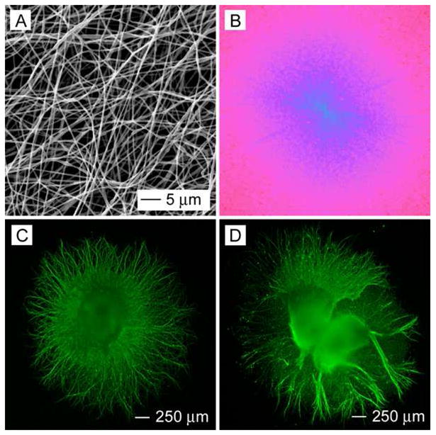
(A) SEM image of a nonwoven mat of randomly oriented PCL nanofibers. (B) A 2–D FFT pattern of the SEM image where the radially symmetrical silhouette is in agreement with a structure lacking directional order. (C, D) Florescence micrographs showing the typical morphology of DRG cultured on a bare (C) and a laminin-coated (D) random PCL nanofiber scaffold, respectively.
Using an approach similar to what we used in our previous studies, aligned PCL nanofibers were collected on a metal frame19–21 and then transferred onto a glass cover slip by lifting them up from the underneath. Figure 2A shows SEM image of a typical sample of aligned PCL nanofibers and the inset shows an FFT pattern, suggesting that the fibers were uniaxially aligned. When DRG were cultured on the aligned PCL nanofibers, we found that the DRG adhered well to the scaffold even without laminin coating and neurites preferred to grow along the long axis of the fiber (Fig. 2B). The fluorescence micrograph in Figure 2B also indicates that some of the neurites initially did not grow along the direction of fiber alignment but could turn their growth directions and eventually grew parallel to the fiber alignment. Similarly, DRG adhered well to aligned PCL nanofibers whose surface had been coated with laminin, and the neurite outgrowth followed the fiber alignment direction (Fig. 2C). We also found that some of the neurites could dramatically change their growth directions (Fig. 2D), showing even sharper turns than on the aligned fibers without a laminin coating. This observation indicates that the laminin coating could greatly enhance the guidance of neurite outgrowth by the underlying nanofibers.
Figure 2.

(A) SEM image of uniaxially aligned PCL nanofibers. The FFT pattern in the inset indicates that the fibers were uniaxially aligned. (B, C) Fluorescence micrographs showing the typical morphology of DRG cultured on the aligned PCL nanofibers (B) without and (C, D) with laminin coating. (D) An enlarged view of (C).
Similar to our previous study, we quantified the average neurite length, the maximum neurite length, and eccentricity of the neurite field using MATLAB (Fig. 3).23 There was no significant difference for the neurite length and eccentricity between bare and laminin-coated samples for random fibers. However, the average length of the neurites increased from 857 μm for laminin-coated, random fibers to 1,085 μm for aligned, bare fibers, and further to 1,542 μm for aligned, laminin-coated fibers (Fig. 3A). The maximum length of neurites projecting from DRG cultured on aligned nanofibers was longer, approximate two-fold greater, than that of neurites projecting from DRG cultured on random nanofibers (Fig. 3B). Laminin-coated, aligned fibers further enhanced the maximum neurite length: approximately 500 μm longer than the bare, aligned nanofibers. Accordingly, the value of eccentricity increased from 0.54 for laminin-coated, random fibers, to 0.82 for aligned, bare fibers, while it was 0.89 for laminin-coated aligned fibers (Fig. 3C). These results clearly demonstrate that aligned nanofibers could promote DRG adhesion and enhance the neurite guidance and extension as compared to random fibers. Laminin coating could further enhance the neurite extension for aligned fibers.
Figure 3.

(A) Eccentricity of neurite field. (B) Average neurite length. (C) Maximum neurite length. × indicates p< 0.05 for samples compared with PCL-R sample. ¤ indicates p< 0.05 for samples compared with PCL-R+Laminin sample. © indicates p< 0.05 for samples compared with PCL-A samples. Abbreviations: PCL-R+Laminin: random PCL nanofibers with laminin coating; PCL-A: aligned PCL nanofibers; and PCL-A+Laminin: laminin-coated PCL-A.
By making use of the collector composed of two metal strips separated by an air gap, we were able to fabricate scaffolds containing both aligned and random nanofibers. Figure 4A shows SEM image of a typical sample where the nanofibers had a clear transition from aligned to random orientation. In this case, the nanofibers were deposited on the metal strips as randomly oriented mats while they were uniaxially aligned across the gap. The insets show FFT patterns taken from these two regions confirming the alignment and randomness of their fibers. Figure 4B shows a fluorescence micrograph of the typical morphology of DRG cultured at the border between the random and aligned fibers. Interestingly, the neurites grew without any preference in orientation on the side with random fibers and grew along the fiber alignment on the side with aligned fibers. Overall, the DRG shows a “Janus feature”, with one side of the neurites uniaxially aligned and the other side radially pointing in different directions. Similar to cultures on uniformly aligned fibers, we observed enhancement of neurite extension and guidance of neurite outgrowth when the nanofibers were pre-coated with laminin before DRG culture (Fig. 4, C and D). Figure 5A shows SEM image of DRG cultured at the border between aligned and random fibers of a laminin-coated scaffold. It can be clearly seen that the neurites on one side of the DRG were randomly distributed on the disordered fibers (Fig. 5B) while those on the other side grew preferentially along the fiber alignment direction (Fig. 5, C and D). Figure 5D also shows cell migration along the direction of fiber alignment.
Figure 4.

(A) SEM image of disorder-to-aligned fiber mat. The FFT patterns in inset indicate that the fibers were aligned on one side and randomly oriented on the other side. (B) Typical morphology of DRG cultured at the border between random and aligned PCL nanofibers (bare). (C) Typical morphology of DRG cultured at the border between random and aligned PCL fibers coated with laminin. The dash line indicates the border line between aligned (right side) and randomly oriented (left side) fibers. (D) An enlarged view of (C).
Figure 5.

(A) SEM images of DRG cultured at the interface between aligned and random PCL fibers with laminin coating. (B–D) Enlarged views of regions B–D indicated in image (A).
Through layer-by-layer stacking, we were able to fabricate multilayered scaffolds of aligned fibers with a specific orientation in each layer. Figure 6 shows SEM images of typical double-layered meshes with low (distance between fibers ≈ 5 μm), mediate (distance between fibers ≈ 1 μm), and high (distance between fibers ≈ 0) densities of fibers where the nanofibers in different layers were rotated by approximately 90° from each other. The FFT patterns shown in Figure 6, A and B, suggest that the mesh consisted of two-layers of uniaxially aligned nanofibers with their orientation rotated by an angle of 80° and 90°, respectively. However, the FFT pattern in the inset of Figure 6C shows a pattern similar to that of uniaxially aligned nanofibers due to a large thickness for the top layer.
Figure 6.
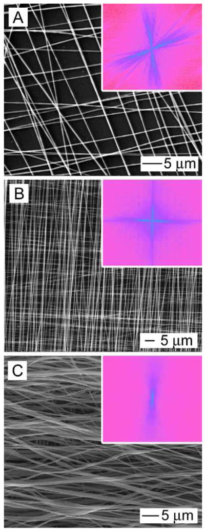
SEM images of double-layered scaffolds with (A) low, (B) mediate, and (C) high fiber densities, where the fibers were uniaxially aligned in each layer and rotated by about 80° to 90°. The FFT patterns in the inset of (A) and (B) indicate that the fibers were crossed with an angle of about 80° and 90°, respectively. The FFT pattern in the inset of (C) is similar to the FFT pattern of uniaxially aligned fibers due to an extremely high density of fibers in the top layer.
When DRG were cultured on the double-layered meshes, the DRG could adhere to all the scaffolds without the application of any laminin. Figure 7A shows a fluorescence micrograph illustrating the typical morphology of DRG cultured on the mesh consisting of bare PCL fibers with a low fiber density. Very few neurites were observed and they tended to grow along the directions of the orthogonal fibers. Figure 7B shows a fluorescence micrograph of DRG cultured on the same kind of scaffold, but with laminin coating. The substrate was pre-coated with poly(ethylene glycol) (PEG) by physical adsorption before the nanofiber mesh was deposited. Compared to the sample without laminin coating, more and longer neurites were observed. More interestingly, we demonstrated for the first time that some of the neurites grew along the long axis of the fibers in one layer and suddenly make a sharp turn to follow the long axis of fibers in the other layer. This can be clearly seen in the inset of Figure 7B. Figure 7C shows the typical morphology of DRG cultured on PCL fiber mesh with a mediate fiber density. Many short neurites were observed and some of the neurites grew along the long axis of underlying fibers and turned to the direction of fiber alignment in the top layer. In contrast, more and longer neurites appeared after coating with laminin and the neurites seemed to form an orthogonal pattern resembling the underlying nanofiber mesh (Fig. 7D). For the samples with a high fiber density, fewer and shorter neurites were noticed on bare scaffolds as compared to the laminin-coated samples (Fig. 7, E and F). However, the neurites were still able to form an orthogonal pattern similar to the underlying nanofiber mesh. In this case, no sharp turn was observed for the neurites. We also investigated the neurite outgrowth on a nanofiber mesh where the PCL fibers were rotated by 60° and the surface was coated by laminin. The fluorescence micrograph of a typical sample indicates the formation of a neurite pattern resembling that of the underlying fiber scaffold (Fig. S1). These results suggest that we might be able to control neurite orientation and formation of complex neural architecture by manipulating both the alignment and assembly of electrospun nanofibers, together with surface coating using cell adhesive extracellular protein such as laminin.
Figure 7.

Fluorescence micrographs showing the typical morphologies of DRG cultured on double-layered meshes composed of uniaxially aligned fibers with (A, B) low, (C, D) mediate, and (E, F) high densities. (B, D, F) The underlying substrate was polystyrene and coated with PEG and the fibers were then coated with laminin.
We further investigated DRG culture on double-layered fiber mats with randomly oriented fibers on the top and aligned fibers at the bottom or vice versa (Fig. 8, A and B, respectively). The insets show their FFT patterns, which are very similar to the pattern from a mat of randomly oriented fibers, except some slight modification due to the presence of aligned fibers. Figure 9, A and B, shows the typical morphology of DRG seeded on these double-layered mats with aligned fibers on the top and randomly oriented fibers at the bottom (A/R) without and with coating of laminin. We found that there was no significant difference in average neurite length on laminin-coated (516 μm) and bare scaffolds (470 μm) (Fig. 10A). In contrast, the maximum neurite length for A/R with laminin coating was significantly longer than the sample without coating (Fig. 10B). Accordingly, the eccentricity for the laminin-coated sample (0.60) was greater than the bare sample (0.33) (Fig. 10C). Figure 9, C and D, shows the typical morphology of DRG cultured on the double-layered mats with randomly oriented fibers on the top and aligned fibers (R/A) at the bottom, without and with laminin coating. The average neurite length was similar for samples with and without laminin coating (Fig. 10A). The maximum neurite length was slightly longer for laminin-coated R/A samples as compared to bare R/A samples (Fig. 10B). Accordingly, their eccentricities were 0.70 and 0.59, respectively (Fig. 10C). A similar observation was made when using aligned fibers with a high fiber density on the top layer and random fibers on the bottom layer (Fig. S2). However, the neurite fields emanating from DRG seeded on R/A samples with dense, random fibers in the top layer exhibited a profile similar to that on random nanofibers (Fig. S3), indicating the neurites could not sense the bottom layer due to the thick layer of random fibers on the top. These results indicate that the nanofibers in the bottom layer also played some role in guiding DRG neurite outgrowth and laminin coating could amplify the role of the fibers in the bottom layer under certain circumstances.
Figure 8.

SEM image of double-layered scaffolds, in which (A) the nanofibers in the top layer were uniaxially aligned and those in the bottom layer were randomly oriented, and (B) vice versa. The insets show the FFT patterns of the corresponding images.
Figure 9.

Fluorescence micrographs showing the morphology of DRG cultured on double-layered mats consisting of (A, C) aligned fibers in the top layer and random fibers in the bottom layer and (B, D) vice versa. The fibers in (B, D) were coated with laminin while those in (A, C) were bare.
Figure 10.

(A) Eccentricity of neurite field. (B) Average neurite length. (C) Maximum neurite length. × indicates p< 0.05 for samples compared with PCL-A/R sample. # indicates p< 0.05 for samples compared with PCL-A/R+Laminin sample. Abbreviations: PCL-A/R: double layered mats consisting of aligned fibers in the top layer and random fibers in the bottom layer; PCL-R/A: vice versa; PCL-A/R+Laminin: laminin-coated PCL-A/R; PCL-R/A+Laminin: laminin-coated PCL-R/A.
Understanding neurite contact guidance is of critical importance for the design of synthetic nerve grafts. It is well-known that contact guidance of neurites can be exerted by topographic features. Also, contact guidance of neurite outgrowth has been extensively investigated using surface features patterned by techniques such as photolithography and microcontact printing.24–26 Although electrospun nanofibers have been examined for the guidance of neurite outgrowth, most of these studies were limited to the use of either random or aligned fibers. In the present work, we have moved one step forward by examining the effects of various nanofiber assemblies with complex structures on the neurite extension and outgrowth guidance.
Previous studies showed that neurite outgrowth could be guided along the direction of aligned electrospun nanofibers.15–17 Our results are in line with the observations of these reports. We also demonstrated that aligned nanofibers could enhance the neurite extension based on the analysis of maximum neurite length. We further established that neurites exhibited two different patterns on two opposite sides of DRG when cultured at the borderline between random and aligned nanofibers. Our study of neurite outgrowth on double-layered fiber meshes may provide valuable information to help us better understand the contact guidance of neurite outgrowth by topographic cues. For example, why do the neurites grow along the fiber alignment direction? During neurite outgrowth, neurite filopodia and lamellipodia which emerge from the growth cone probe the surrounding extracellular microenvironment for neuronal growth-cone pathfinding and these cytoskeleton structures rich in microtubules and actin filaments yield traction forces that push and pull the neurite forward.27, 28 The direction of neurite extension is caused by the strength of the traction force exerted by the filopodia and this force is determined by the extent to which these protein filaments can accumulate, assemble, and orient in the direction of a cell protrusion.6, 29 In view of our results, we believe the mechanisms used by the aligned nanofibers to control the neurite orientation can be summarized as follows. When DRG were cultured on the surface of a scaffold of random nanofibers, the strength of the traction force exerted by the filopodia was uniform in all directions. As a result, neurites emerged from the DRG main body in all directions and exhibited a radial distribution surrounding DRG main body (Fig. 1). When cultured on the surface of aligned nanofibers, the strength of the traction force exerted by the filopodia was not uniform in all directions any more due to the anisotropic properties of the aligned fibers. In this case, neurites may prefer to extend along the fibers instead of stepping across them (Fig. 2, B–D). One previous study, however, reported that microtubules and actin filaments within the cytoplasm are too rigid to allow considerable deformation of filopodia to accommodate alterations of topography.30 This conclusion is in contradiction to what we have observed in the present work (Fig. 6E).
During development, the ECM directs the axons of maturing neurons to their innervating targets through a combination of contact-mediated (e.g., laminin) and soluble factors such as neurotrophin NT-3.31 Laminin, an ECM glycoprotein, promotes neurite outgrowth via multiple cell-adhesion sites.32 Binding of laminin to neuronal surface integrins is required for proper neural crest migration. Laminin also supports neurite outgrowth from cultured explants and modulates the guidance of growth cones in response to extracellular cues.33–35 The electrospun nanofiber itself can be functionalized by encapsulation or attachment of biochemical cues to improve its biomimetic capability. One recent study showed coupling laminin with electrospun poly(L-lactic acid) (PLLA) nanofibers could enhance the neurite extension of PC12 cells.36 In this study, we demonstrated that immobilization of laminin on the surface of PCL nanofibers through electrostatic interaction between poly-L-lysine and laminin could enhance neurite guidance and extension. PEG coating on the substrate might be beneficial to the neurite guidance by nanofibers in that PEG is one of the best-known non-fouling biomaterials with extremely low energy and non-adhesive surfaces.37 We also found that neurites could make a sharp turn upon encountering the fibers in another layer with a different orientation when DRG were cultured on a double-layered nanofiber scaffold (with laminin coating and low fiber density) supported on a PEG-coated polystyrene substrate. Combined together, these results clearly suggest that electrospun nanofibers can serve as a class of versatile scaffolds for controlling the fabrication of neural networks.
CONCLUSION
We have demonstrated that electrospinning can generate a variety of nanofiber assemblies, which can serve as a new platform for investigating the outgrowth of neurites. When DRG were cultured on nanofiber scaffolds, the neurites were evenly distributed on scaffolds consisting of random fibers and grew preferentially along the fibers on uniaxially aligned samples. When seeded at the border between aligned and random fibers, the neurites originating from the same DRG could simultaneously grow into both aligned and random structures. Moreover, by stacking electrospun nanofibers into double-layered meshes, the neurites could be guided to grow into complex patterns, and the nanofibers in both layers could provide the guidance. For all scaffolds consisting of PCL nanofibers, the effectiveness of guidance could be further improved by coating the surface with laminin. Taken together, these results could contribute to a better design of new scaffolds for nerve repair and lead to a more thorough understanding of neurite outgrowth behavior on electrospun nanofibers.
EXPERIMENTAL METHODS
Fabrication and characterization of nanofiber assemblies
The nanofibers were produced by electrospinning and the setup was similar to what we used in previous studies.[11, 18–21] Poly(ε-caprolactone) (PCL) (Mw=65,000 g/mol; Sigma-Aldrich, St. Louis, MO) was dissolved in a solvent mixture consisting of dichloromethane (DCM) and N, N-dimethylformamide (DMF) (Fisher Chemical, Waltham, MA) with a ratio 8:2 (v/v) at a concentration 20% (w/v). Polymer solution was pumped at a flow rate of 0.2 mL/h using a syringe pump. A DC high voltage of 12 kV was applied between the nozzle (a 22-gauge needle) and a grounded collector. Different collectors were employed to generate different types of nanofiber assemblies. Random nanofibers were directly collected using cover glass slips. A stainless steel frame (with an open void of 2 cm × 5 cm) was used as the collector. Subsequently, the aligned nanofibers were easily transferred to the cover glass slips by lifting off the fibers. Samples containing both random and aligned fibers next to each other were obtained by using two metal frames separated by an air gap. Fibers were deposited in the random and aligned form on the metal part and across the air gap, respectively.
The electrospun PCL nanofibers were coated with laminin (Millipore, Temecular, CA) as the following. The electrospun fibers were immersed in a 0.1% poly-L-lysine (PLL) (Sigma-Aldrich) solution for 1 h at room temperature, followed by washing with phosphate buffered saline (PBS) buffer (Invitrogen) three times. Subsequently, the nanofiber sample was immersed in a laminin solution (26 μL 50 μg/mL laminin solution diluted with 5 mL PBS buffer) at 4 °C overnight. Prior to DRG seeding, the nanofiber scaffold was rinsed with PBS buffer three times.
PEG (Mw=8,000 g/mol, Sigma-Aldrich) coating on the polystyrene substrate was completed by physical adsorption. Briefly, the small piece of polystyrene substrate fabricated by cutting Petri dishes was immersed in a 1% PEG solution overnight, followed by washing with water three times.
The morphologies and structures of various fiber assemblies were characterized by scanning electron microscopy (SEM) (200 NanoLab, FEI, Oregon). To avoid charging, the polymer fiber samples were coated with platinum using a sputter coater for 40 sec in vacuum at a current intensity of 40 mA after the sample had been fixed on a metallic stud with double-sided conductive tape. The accelerating voltage was 15 kV for the imaging process.
FFT analysis was performed by utilizing the FFT function of the Scion Image processing software. The detailed information on measuring fiber alignment by FFT can be found in an excellent review article.38 The spatial information presented by an image can be processed into a mathematically defined frequency domain using 2D FFT function. The frequency domain maps the rate where pixel intensities vary in the spatial domain. Pixel intensities and the intensity distraibution of the resulting image correspond to the directional content of the original image and the results of the FFT yields frequencies orthogonal to those in the original image.15, 17, 38–40
DRG culture
Embryonic day 8 (E8, stage HH35–36) chicks were removed from the eggs and decapitated. DRG were dissected from the thoracic region and collected in Hank’s buffered salt solution (HBSS) prior to plating. DRG were then placed onto the nanofiber scaffolds (1 DRG per sample) and incubated for 6 days in modified neurobasal (NB) media containing NB media, 1% ABAM, 1% N-2 supplement, (Invitrogen, Carlsbad, CA) and 30 ng/mL rhβ-nerve growth factors (NGF) (R&D system, Minneapolis, MN).
SEM characterization of DRG
The DRG were fixed in 3.7% formaldehyde for 30 min. Subsequently, it was dehydrated in ethanol with a series of concentrations (30%, 50%, 70%, 90%, 95%, and 100%) and dried in vacuum. Finally, the sample was coated with platinum using a sputter prior to imaging by SEM. The accelerating voltage was 15 kV for imaging.
DRG Immunostaining
After 6 days incubation, the DRG were immunostained with the marker anti-neurofilament 200 (Sigma-Aldrich). Briefly, the DRG were fixed in 3.7% formaldehyde for 45 min and permeabilized by 0.1% Triton x-100 for 30 min. Then it was blocked in PBS containing 5% normal goat serum (NGS) (Invitrogen) for 1 h. Primary antibody diluted with PBS that contained 2% NGS was applied to the cells overnight at 4 °C. The anti-neurofilament 200 marker was detected using AlexaFluor 488 goat anti-mouse IgG (1:200; Invitrogen) secondary antibody. After staining, fluorescent images were taken using a QICAM Fast Cooled Mono 12-bit camera (Q Imaging) attached to an Olympus microscope with Capture 2.90.1 (Olympus). Eccentricity of the neurite field, maximum length of extending neurites, and average length of extending neurites were simultaneously calculated from fluorescent images using custom-designed image processing software constructed in MATLAB (MathWorks Inc.). Neurite field eccentricity and length of neurite extension were specifically calculated for each sample as established measures of directed neurite growth and rate of neurite growth, respectively. Quantitative analysis was accomplished by separately fitting both the leading edge of the neurite field and the perimeter of the DRG cell mass, identified using 10 user-selected points, to a standard elliptical equation (1):41
| (1) |
where point (h, k) is the center of the elipse and a and b are the ellipse’s semimajor and semiminor axes. Eccentricity of the neurite field was then calculated using equation (2):
| (2) |
Values of a and b were obtained from the specific elliptical equation fit to the leading edge of the neurite field. Average and maximum length of neurite extension were then calculated as the average distance and the greatest distance between the elliptical curve identifying the border of the DRG cell mass and the elliptical curve identifying the leading edge of the neurite field along a line oriented radially from the center of the DRG cell mass. Mean values and standard deviation were reported (n=4–8). Statistical analysis of average neurite length, maximum neurite length, and eccentricity of neurite field was performed using the Scheffe’s post hoc test by analysis of variance at a 95% confidence level.
Supplementary Material
Acknowledgments
This work was supported in part by an NIH Director’s Pioneer Award (DP1 OD000798) and start-up funds from Washington University in St. Louis. X.L. is a visiting Ph.D. student from the School of Materials Science and Engineering, Tianjin University, Tianjin, China and has been partially supported by the National Council of Scholarship.
REFERENCES AND NOTES
- 1.Yu TW, Bargmann CI. Dynamic Regulation of Axon Guidance. Nature Neurosci. 2001;4:1169–1176. doi: 10.1038/nn748. [DOI] [PubMed] [Google Scholar]
- 2.Lamoureux P, Ruthel G, Buxbaum RE, Heidemann SR. Mechanical Tension Can Specify Axonal Fate in Hippocampal Neurons. J Cell Biol. 2002;159:499–508. doi: 10.1083/jcb.200207174. [DOI] [PMC free article] [PubMed] [Google Scholar]
- 3.Patel N, Poo M. Orientation of Neurite Growth by Extracellular Electric Fields. J Neurosci. 1982;2:483–496. doi: 10.1523/JNEUROSCI.02-04-00483.1982. [DOI] [PMC free article] [PubMed] [Google Scholar]
- 4.Kim S, Im WS, Kang L, Lee ST, Chu K, Kim BI. The Application of Magnets Directs the Orientation of Neurite Outgrowth in Cultured Human Neuronal Cells. J Neurosci Methods. 2008;174:91–96. doi: 10.1016/j.jneumeth.2008.07.005. [DOI] [PubMed] [Google Scholar]
- 5.Song M, Uhrich KE. Optimal Micropattern Dimensions to Enhance Neurite Outgrowth Rates, Lengths and Orientations. Ann Biomed Eng. 2007;35:1812–1820. doi: 10.1007/s10439-007-9348-0. [DOI] [PubMed] [Google Scholar]
- 6.Mahoney MJ, Chen RR, Tan J, Saltzman WM. The influence of Microchannels on Neurite Growth and Architecture. Biomaterials. 2005;26:771–778. doi: 10.1016/j.biomaterials.2004.03.015. [DOI] [PubMed] [Google Scholar]
- 7.Rajnicek M, Britland S, McCaig C. Contact Guidance of CNS Neurites on Grooved Quartz: Influence of Groove Dimensions, Neuronal Age and Cell Type. J Cell Sci. 1997;110:2905–2913. doi: 10.1242/jcs.110.23.2905. [DOI] [PubMed] [Google Scholar]
- 8.Goldner JS, Bruder JM, Lim G, Gazzola D, Hoffman-Kim D. Neurite Bridging across Micropatterned Grooves. Biomaterials. 2006;27:460–472. doi: 10.1016/j.biomaterials.2005.06.035. [DOI] [PubMed] [Google Scholar]
- 9.Gomez N, Lu Y, Chen S, Schmidt CS. Immobilized Nerve Growth Factor and Microtopography Have Distinct Effects on Polarization Versus Axon Elongation in Hippocampal Cells in Culture. Biomaterials. 2007;28:271–284. doi: 10.1016/j.biomaterials.2006.07.043. [DOI] [PubMed] [Google Scholar]
- 10.Reneker DH, Yarin AL. Electrospinning Jets and Polymer Nanofibers. Polymer. 2008;49:2387–2425. [Google Scholar]
- 11.Li D, Xia Y. Electrospinning of Nanofibers: Reinventing the Wheel? Adv Mater. 2004;16:1151–1170. [Google Scholar]
- 12.Xie J, Li X, Xia Y. Put Electrospun Nanofibers to Work for Biomedical Research. Macromol Rapid Comm. 2008;29:1775–1792. doi: 10.1002/marc.200800381. [DOI] [PMC free article] [PubMed] [Google Scholar]
- 13.Burger C, Hsiao BS, Chu B. Nanofibrous Materials and Their Applications. Ann Rev Mater Res. 2006;36:333–368. [Google Scholar]
- 14.Yang F, Murugan R, Wang S, Ramakrishna S. Electrospinning of Nano/micro Scale Poly(L-lactic acid) Aligned Fibers and Their Potential in Neural Tissue Engineering. Biomaterials. 2005;26:2603–2610. doi: 10.1016/j.biomaterials.2004.06.051. [DOI] [PubMed] [Google Scholar]
- 15.Corey JM, Lin DY, Mycek KB, Chen Q, Samuel S, Feldman EL, Martin DC. Aligned Electrospun Nanofibers Specify the Direction of Dorsal Root Ganglia Neurite Growth. J Biomed Mater Res. 2007;83A:636–645. doi: 10.1002/jbm.a.31285. [DOI] [PubMed] [Google Scholar]
- 16.Schnell E, Klinkhammer K, Balzer S, Brook G, Klee D, Dalton P, Mey J. Guidance of Glial Cell Migration and Axonal Growth on Electrospun Nanofibers of Poly-e-caprolactone and a Collagen/poly-e-caprolactone Blend. Biomaterials. 2007;28:3012–3025. doi: 10.1016/j.biomaterials.2007.03.009. [DOI] [PubMed] [Google Scholar]
- 17.Chow WN, Simpson DG, Bigbee JW, Colello RJ. Evaluating Neuronal and Glial Growth on Electrospun Polarized Matrices: Bridging the Gap in Percussive Spinal Cord Injuries. Neuron Glia Biology. 2007;3:119–126. doi: 10.1017/S1740925X07000580. [DOI] [PMC free article] [PubMed] [Google Scholar]
- 18.Patel S, Kurpinski K, Quigley R, Gao H, Hsiao BS, Poo MM, Li S. Bioactive Nanofibers: Synergistic Effects of Nanotopography and Chemical Signaling on Cell Guidance. Nano Lett. 2007;7:2122–2128. doi: 10.1021/nl071182z. [DOI] [PubMed] [Google Scholar]
- 19.Li D, Xia Y. Direct Fabrication of Composite and Ceramic Hollow Nanofibers by Electrospinning. Nano Lett. 2004;4:933–938. [Google Scholar]
- 20.Li D, Wang Y, Xia Y. Electrospinning of Polymeric and Ceramic Nanofibers as Uniaxially Aligned Arrays. Nano Lett. 2003;3:1167–1171. [Google Scholar]
- 21.Li D, Wang Y, Xia Y. Electrospinning Nanofibers as Uniaxially Aligned Arrays and Layer-by-Layer Stacked Films. Adv Mater. 2004;16:361–366. [Google Scholar]
- 22.Li D, Gong O, McCann JT, Xia Y. Collecting Electrospun Nanofibers with Patterned Electrodes. Nano Lett. 2005;5:913–916. doi: 10.1021/nl0504235. [DOI] [PubMed] [Google Scholar]
- 23.Xie J, Willerth SM, Li X, Macewan MR, Rader A, Sakiyama-Elbert SE, Xia Y. The Differentiation of Embryonic Stem cells seeded on Electrospun Nanofibers into Neural Lineages. Biomaterials. 2009;30:354–362. doi: 10.1016/j.biomaterials.2008.09.046. [DOI] [PMC free article] [PubMed] [Google Scholar]
- 24.Johansson F, Carlberg P, Danielsen N, Montelius L, Kanje M. Axonal Outgrowth on Nano-imprinted Patterns. Biomaterials. 2006;27:1251–1258. doi: 10.1016/j.biomaterials.2005.07.047. [DOI] [PubMed] [Google Scholar]
- 25.Cecchini M, Bumma G, Serresi M, Beltram F. PC12 Differentiation on Biopolymer Nanostructures. Nanotechnology. 2007;18:505103. [Google Scholar]
- 26.Philipsborn ACV, Lang S, Bernard A, Loeschinger J, David C, Leh D. Microcontact Printing of Axon Guidance Molecules for Generation of Graded Patterns. Nature Protocol. 2006;1:1322–1328. doi: 10.1038/nprot.2006.251. [DOI] [PubMed] [Google Scholar]
- 27.Gallo G, Letourneau PC. Axon Guidance: Proteins Turnover in Turning Growth Cones. Current Biol. 2002;12:R560–R562. doi: 10.1016/s0960-9822(02)01054-0. [DOI] [PubMed] [Google Scholar]
- 28.Mattila PK, Lappalainen P. Filopodia: Molecular Architecture and Cellular Functions. Nature Rev Mol Cell Biol. 2008;9:446–454. doi: 10.1038/nrm2406. [DOI] [PubMed] [Google Scholar]
- 29.Tan J, Saltzman WM. Topographical Control of Human Neutrophil Motility on Micropatterned Materials with Various Surface Chemistry. Biomaterials. 2002;23:3215–3225. doi: 10.1016/s0142-9612(02)00074-1. [DOI] [PubMed] [Google Scholar]
- 30.Dunn GA, Heath JP. A New Hypothesis of Contact Guidance in Tissue Cells. Exp Cell Res. 1976;101:1–14. doi: 10.1016/0014-4827(76)90405-5. [DOI] [PubMed] [Google Scholar]
- 31.Yu LMY, Leipzig ND, Shoichet MS. Promoting Neuron Adhesion and Growth. Materials Today. 2008;11:36–43. [Google Scholar]
- 32.Powell SK, Kleinman HK. Neuronal Laminins and Their Cellular Receptors. Int J Biochem Cell Biol. 1997;29:401–414. doi: 10.1016/s1357-2725(96)00110-0. [DOI] [PubMed] [Google Scholar]
- 33.Lallier T, Deutzmann R, Perris R, Bronner-Fraser M. Neural Crest Cell Interactions with Laminin: Structural Requirements and Localization of the Binding Site for α1β1 Integrin. Dev Biol. 1994;162:451–464. doi: 10.1006/dbio.1994.1101. [DOI] [PubMed] [Google Scholar]
- 34.McKenna MP, Raper JA. Growth Cone Behavior on Gradients of Substratum Bound Laminin. Del Biol. 1988;130:232–236. doi: 10.1016/0012-1606(88)90429-0. [DOI] [PubMed] [Google Scholar]
- 35.Hopker VH, Shewan D, Tessier-lavigne M, Poo M, Halt C. Growth-cone Attraction to Netrin-1 is Converted to Repulsion by Laminin-1. Nature. 1999;401:69–73. doi: 10.1038/43441. [DOI] [PubMed] [Google Scholar]
- 36.Koh HS, Yong T, Chan CK, Ramakrishna S. Enhancement of Neurite Outgrowth using Nano-structured Scaffolds Coupled with Laminin. Biomaterials. 2008;29:3574–3582. doi: 10.1016/j.biomaterials.2008.05.014. [DOI] [PubMed] [Google Scholar]
- 37.Saneinejad S, Shoichet MS. Patterned Poly(chlorotrifluoroethylene) Guides Primary Nerve Cell Adhesion and Neurite Outgrowth. J Biomed Mater Res. 2000;50:465–474. doi: 10.1002/(sici)1097-4636(20000615)50:4<465::aid-jbm1>3.0.co;2-k. [DOI] [PubMed] [Google Scholar]
- 38.Ayres C, Bowlin GL, Henderson SC, Taylor L, Shultz J, Alexander J, Telemeco TA, Simpson DG. Modulation of Anisotropy in Electrospun Tissue-Engineering Scaffolds: Analysis of Fiber Alignment by the Fast Fourier Transform. Biomaterials. 2006;27:5524–5534. doi: 10.1016/j.biomaterials.2006.06.014. [DOI] [PMC free article] [PubMed] [Google Scholar]
- 39.Ayres CE, Shekhar JHAB, Meredith H, Bowman JR, Bowlin GL, Henderson SC, Simpson DG. Measuring Fiber Alignment in Electrospun Scaffolds: a User’s Guide to the 2D Fast Fourier Transform Approach. J Biomater Sci Polymer Edn. 2008;19:603–621. doi: 10.1163/156856208784089643. [DOI] [PubMed] [Google Scholar]
- 40.San S, Corey JM, Gertz CC, Wang B, Birrell LK, Johnson SL, Martin DC, Feldman EL. The Design of Electrospun PLLA Nanofiber Scaffolds Compatible with Serum-free Growth of Primary Motor and Sensory Neurons. Act Biomater. 2008;4:863–875. doi: 10.1016/j.actbio.2008.02.020. [DOI] [PMC free article] [PubMed] [Google Scholar]
- 41.Halif R, Flusser J. Numerically Stable Direct Least Squares Fitting of Ellipses. Proc Sixth Int Conf Comp Graph Visual. 1998;1:125. [Google Scholar]
Associated Data
This section collects any data citations, data availability statements, or supplementary materials included in this article.