

Abstract
Electrowetting-on-dielectric (EWOD) actuation enables digital (or droplet) microfluidics where small packets of liquids are manipulated on a two-dimensional surface. Due to its mechanical simplicity and low energy consumption, EWOD holds particular promise for portable systems. To improve volume precision of the droplets, which is desired for quantitative applications such as biochemical assays, existing practices would require near-perfect device fabricaion and operation conditions unless the droplets are generated under feedback control by an extra pump setup off of the chip. In this paper, we develop an all-electronic (i.e., no ancillary pumping) real-time feedback control of on-chip droplet generation. A fast voltage modulation, capacitance sensing, and discrete-time PID feedback controller are integrated on the operating electronic board. A significant improvement is obtained in the droplet volume uniformity, compared with an open loop control as well as the previous feedback control employing an external pump. Furthermore, this new capability empowers users to prescribe the droplet volume even below the previously considered minimum, allowing, for example, 1:x (x < 1) mixing, in comparison to the previously considered n:m mixing (i.e., n and m unit droplets).
1. Introduction
In microfluidics or micro total analysis systems (μTAS), precise liquid handling is essential for many applications, such as drug discovery or quantitative analysis, because the accuracy of the assay fully depends on the dose of the reagents [1]. One may consider two types of microfluidics. The first is most common and involves a continuous fluid flow through micro-scale channels. The second type is of the interest of this paper and involves discrete fluid packets manipulated inside the micro-channel or on a two-dimensional surface.
To achieve a highly precise liquid handling in continuous-flow microfluidics, the flow rate can be monitored by a flow sensor and regulated by on-chip pumps or valves with feedback control [2, 3]. In digital microfluidics, where the flow rate is determined by the number of droplets, two key parameters for precise liquid handling are the volume accuracy and repeatability of the droplets, a droplet being the basic unit of the digital microfluidic system. Digitizing (i.e., droplet creation) is an essential process to define the droplet volume. When droplets are carried along a continuous flows in what may be considered a pseudo-digital microfluidics, a T-shape channel was used to generate droplets from bulk liquid and precise control was achieved by regulating the flow rates [4]. However, a true digital microfluidic system would operate without carrier flows and preferably without any micro-channels that hampers reconfigurability. Such digital microfluidics can be realized by driving mechanisms acting on the droplets locally, i.e., on individual droplets [5, 6]. Many driving mechanisms have been studied, such as electrocapillary [7], thermocapillary [8] or along with local vapor pressure [9], chemical gradient [10], acoustic wave [11], magnetic field [12] and electric field (electrostatic [13, 14], dielectrophoresis (DEP) [15], or electrowetting-on-dielectric (EWOD) [16]). Electrical mechanisms tend to be more compatible with miniaturization, EWOD being particularly promising because it uses simple device configuration and fabrication, generates large force in microscale, and consumes little energy (i.e., does not heat up). Manipulation of aqueous droplets have been demonstrated in the typical parallel-plate EWOD device filled with oil [16] or dry in air [17].
To split a water droplet in a dry device solely by EWOD actuation (i.e., all electronic and not assisted by an external pressure source), Cho et al. analyzed the gap between the two plates should be smaller than the critical value determined by material and device parameters [18]. They further demonstrated an all-electronic droplet generation on chip by drawing a liquid column out from an on-chip reservoir and having the column break on the creation electrode by activating a series of electrodes in a certain sequence. It was the first success for droplet generation in air (i.e., not immersed in oil) by pure electric signals (i.e., no pressure assistance), all on chip (i.e., no use of syringe). This basic approach, however, leaves the cutting and generating process subject to many uncertainties, which affect reproducibility. When a droplet is formed from a reservoir, the liquid bridge pinches off essentially by fluid instability. The generated volume is difficult to predict and control as it is affected not only by operation parameters (e.g., actuation sequence, driving voltage, and signal duration) but also by many random parameters (e.g., surface roughness, hydrophobic coating, dielectric layer properties and thickness, and environmental humidity, as well as their long-term time dependency). Each of these factors changes the droplet response even under the same driving voltage and sequence. Lastly, EWOD devices fabricated on single conductive layer substrates have the connecting lines beside or often right next to the actuation electrodes. These connecting lines, although very narrow, may also affect the droplet volume at high creation voltage.
Another approach to generate droplets inside EWOD device is to use an external pressure source to assist droplet generation. In this hybrid (i.e., not all-electronic) approach, the controlled external pressure source pumps a prescribed liquid volume into the device, and then the EWOD actuation either holds or moves the droplet away to the next position [19]. Droplet volume accuracy and reproducibility were still affected by the system uncertainty until Ren et al. developed a system consisting of droplet dispensing from a syringe pump and on-chip droplet volume metering [20]. In this feedback control scheme, the pumped liquid volume is monitored by on-chip capacitance measurement. When the volume reached the target number, the electrodes nearby the pump nozzle (i.e., syringe tip) were actuated to move the droplet away. Although droplets were generated reproducibly at a high dispensing rate with this method, the extra pump set-up and complicated device assembly compromised the simplicity of EWOD digital microfluidics systems. Recall the main advantage of EWOD systems is microfluidics without pumps or valves. Our goal remains to exercise the simplicity EWOD presents and ultimately develop a compact microfluidic system consisting of only a microfluidic chip and an electronic board with no connections other than electrical [21].
Recently Gong et al. demonstrated control of droplet volume on a multilayer printed circuit board (PCB) EWOD device with through-substrate electrical connections to eliminate the side connecting lines [22]. By simple electrical signal switching, reasonable droplet volume precision (± 5%) has been demonstrated under a well controlled lab environment [23]. Changing the driving voltage to tune the droplet volume within a certain range (± 10%) has also been demonstrated. The experiments suggested feedback control of the driving voltage for on-chip droplet generation can be developed to overcome the uncertainty and achieve reproducible droplet volumes [24]. In this paper, we show an all-electronic real-time feedback system for on-chip droplet generation by combining precise capacitance droplet volume sensing and high voltage actuations. We will also discuss the control algorithms, device performance under feedback control, and new digital microfluidic functions realized by feedback control.
2. EWOD device and droplet creation process
2.1 EWOD device on multi-layer PCB
The EWOD devices in this paper were fabricated on top of a multi-layer PCB substrate in a direct-referencing configuration and free of side connection lines, following the procedures described elsewhere [22]. As shown in Fig. 1, a four-layer PCB substrate with conductive polymer filled vias was first lapped and polished by chemical mechanical polishing (CMP), deposited with 2000 Å Au, patterned into a two-dimensional electrode array, and then deposited with 8000 Å parylene C as the dielectric layer and 2000 Å Teflon® AF1600 as the hydrophobic coating [22]. The top glass was coated with 2000 Å transparent ITO as a ground electrode and 2000 Å Teflon® as hydrophobic coating. A top glass was positioned above the EWOD-PCB substrate by appropriate spacers. For the EWOD operation, the device can be used dry (i.e., exposed to air) or filled with low viscosity silicone oil (1 cSt). In this paper, the EWOD chip has 1.5 mm × 1.5 mm electrode pads and a 100 μm spacer between the parallel plates. This low aspect ratio (spacer height / electrode size = 1/15) is chosen to meet the criterion for droplet pinch-off [18]. The control circuit can access the two-dimensional array through the connection pads on the PCB-EWOD chip substrate and the socket on the control board [22, 25].
Figure 1.
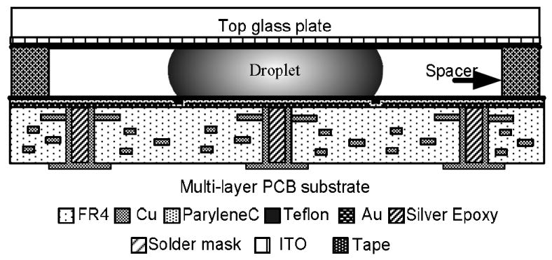
Direct-referencing EWOD chip fabricated with four-layer printed circuit board (PCB) technology [22]. This type of device is used for the experiments in this paper.
2.2 Droplet pinch-off process on EWOD device
A liquid jet in free space or on an open surface is hydrodynamically unstable, and small perturbations of the liquid column at certain wavelengths will self-amplify until the whole liquid jet breaks into small droplet beads [26]. However, for a liquid squeezed between two parallel plates, such as in the current EWOD device configuration, the liquid column is stable; most small perturbations or disturbances would decay away [18]. For that reason, droplet cutting inside a parallel-plate EWOD device requires active stretching of a droplet from its two ends, while a liquid column on an open surface breaks by itself into multiple droplets [27]. As shown in Fig. 2(a), a droplet can be generated from a reservoir when the liquid is first elongated along the series of electrodes by turning them on (to wetting) and then turning the middle electrode off (to nonwetting) while keeping the reservoir and creation site wetting. As a result, the meniscus on the middle electrode starts to contract, governed by the constant total volume of the liquid. The neck of the droplet, negative Rs, should keep decreasing until the droplets are finally separated. Mathematically, droplet breakup inside the two-dimensional Hele-Shaw cell model is an infinite time process governed by two-dimensional hydrodynamic equations [28]. However, in the physical world with three dimensions, when the neck is small enough (such as close to the gap height between the plates), hydrodynamic instability comes into effect, allowing the neck to break.
Figure 2.
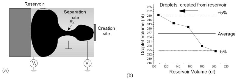
All-electronic, voltage-controlled (open loop) on-chip droplet creation process on EWOD device. (a) The droplet is elongated by applying the voltages Vr and Vc at reservoir and creation sites, respectively, to pump liquid out of the separation site and form negative curvature Rs, (b) Experimental results of generated droplet volume vs. reservoir volume before generation under open loop control. The reservoir is not replenished while the droplets are pulled out.
The droplet pinch-off process can be examined following Cho et al. [18]. We extend their analysis to address the droplet generation case with different geometries of reservoir, creation site, and separation site. Through the Laplace-Young equation relating pressure difference with droplet geometry and EWOD equation relating droplet contact angle with applied voltage, the droplet shape and applied voltages can be used to calculate the pressure differences between each electrode site as shown in Eqs. (1) and (2).
| (1) |
| (2) |
Here, ΔPsr or ΔPsc denotes the pressure difference between the separation site and the reservoir or creation site, Rs,r,c is the droplet curvature (top view) at each electrode site, Vr,c is the voltage applied to the reservoir and creation sites, γLG is the surface tension of liquid over gas (72.86 × 10⁻³ N/m for water-air), ε0 is the permittivity of the vacuum (8.85 × 10⁻¹² F/m), ε is the dielectric constant of the dielectric layer (3.15 for parylene C), t is its thickness (8000 Å), and d is the gap height of the EWOD device (100 μm). These equations can be further extended to analyze dynamic states if the curvatures and voltages are all considered to be time-dependent. When voltages are applied to the reservoir and creation sites, EWOD actuation is pumping the liquid to the reservoir and creation sites. As the liquid is pulled away from the separation site, a neck is formed on it, and so both Rs and ΔP decrease. Due to the contact angle saturation of the EWOD actuation[18], there’s the upper limitation of the EWOD forces. Since droplet pinch-off requires a decreased neck, if the channel height d is too large and the EWOD term becomes small, EWOD actuation may not significant enough to overcome the capillary forces. By assuming the required Rs to separate the droplet is half the size of separation length, Cho et al. estimated the minimum Rs/d that allows the separation when the maximum EWOD force is determined by contact angle saturation [18]. In this case, ΔP can be kept positive until droplet pinch-off by applying high enough voltages.
To calculate the droplet volume at the creation site, the flow rate from the separation site to the creation site must be known. Reynolds Number for EWOD systems is , where ρ is the liquid density, vs is the mean fluid velocity at the separation site, L is the characteristic length, and μ is dynamic fluid viscosity. By measuring the droplet meniscus movement under EWOD actuation with a high-speed camera (Phantom V6.5, maximum speed at 5000 frame/sec), the mean fluid velocity of deionized (DI) water was estimated as 1 – 10 mm/s. If L is considered to be the length of the liquid neck (~ 1 mm), the typical Reynolds number (Re) for DI water in the current EWOD device ranges from 1 to 10. With this low Re and under an obvious laminar condition, Poiseuille flow is assumed inside the droplet. As shown in Eq. (3), the volume change on the creation site is proportional to the pressure difference ΔP. So the created droplet volume can be calculated by integrating ΔVc from when voltage is first applied until droplet pinch-off has occurred (Eq. (4)).
| (3) |
| (4) |
Although the voltage and the droplet radius of curvature at the reservoir (Vr and Rr, respectively) are not explicitly seen in Eqs. (3) and (4), they are actually implicitly included because Rc depends on Vr and Rr through Eq. (1). The parameters in all of the equations can be divided into two groups: the capillary part by droplet shape (Rr,s,c) and the EWOD part by applied voltages (Vr,c). Ideally, to have a repeatable droplet volume, both the droplet shape and the applied voltages should remain the same for all the droplet creation steps. However, open-loop voltage control cannot guarantee such a condition. First, although the EWOD actuation is more significant than capillary forces in the current EWOD configurations (1.5 mm electrode, 100 μm space height, 8000 Å parylene C, and 80 V applied voltages lead to ~ 1000 m−1 for the capillary effects and ~ 7000 m−1 for the EWOD effect), the accumulated error due to capillary forces is not trivial. For example, during droplet generation, the shape of liquid at the initial stage will influence its shape during creation procedure and then the final droplet volume generated. As shown in Fig. 2(b), as droplets continued to be generated without replenishing the reservoir, the generated droplet volume increased under a given voltage sequence. The created droplet volume increased more than 10% when the reservoir volume decreased to 50%. Secondly, as mentioned in Introduction, any uncontrollable variations such as surface defects, dielectric charging, fabrication variations, and operation environment may change the contact angle or droplet shape response under EWOD voltage and cause an offset of droplet volume. Finally, the exact time of droplet pinch-off cannot be controlled. Because droplet pinch-off occurs in the final stage of droplet generation when the neck is narrow and the flow rate is low, the volume variation may be small. However, if the droplet is inside oil, the pinch-off occurs more rapidly with less confinement from the top and bottom surfaces, so fluctuation of the pinch-off timing remains a significant parameter affecting the final generated volume. The droplet volume variation was indeed found larger when the same droplet-generation operation was performed in an oil-filled device.
3. Real-time feedback control during on-chip droplet generation
Due to the many parameters involved in generating droplets, a real-time feedback control is desired to monitor droplet volume and control applied voltages for on-chip droplet generation of constant volumes. The previously reported feedback control system [20] monitored the droplet volume being pumped into the system from an external pressure source but not the volume of the droplet leaving the nozzle on the device surface. However, controlling the droplet volume during the pinch-off and detachment is more important because of the uncertainties in the droplet separation as mentioned above. To solve this problem, we recognize it is possible to control the detachment volume until the actual separation if the pressure difference is constantly adjusted during the pinch-off through the EWOD voltages until the last moment, as shown in Eq. (2). Note the pressure is generated on chip by EWOD actuation, not by an external pressure source. This all-electronic voltage mechanism, applied directly to the droplet, has much better control on the droplet process than the hybrid method using an external pump, which has to act on the droplet through a large dead volume in the accompanying flow system. The liquid cannot be pumped in and retracted back as fast as the voltage mechanism, which acts directly on the droplet, allows. In this paper, we develop an on-chip real-time feedback control system comprised of three parts: droplet volume sensors, high voltage actuators, and a feedback controller. Digital discrete-time feedback control hardware is used because it allows the control parameters and algorithms to be changed by software. The control system is implemented by modifying both the hardware and software in the electronic operation system but with no change in the EWOD chip, i.e., the feedback capability is added practically free.
3.1 Real-time capacitive measurement of droplet volume
The droplet volume inside the EWOD device can be calculated by multiplying the measured droplet footprint area with the spacer height. The calculation error due to the curvature of the free surface on the droplet side is less than 1% if aspect ratio (height/diameter) is low (< 1/10) and the contact angle of droplet on the surface is around 90° (it is 70 – 113° for water on a Teflon surface under EWOD). The footprint area can be quantified through electrical measurement of the capacitance between the electrodes on the top and bottom plates [5]. As shown in Fig. 3(a), the equivalent circuit model of an EWOD device, both the dielectric layer (8000 Å parylene C) and the droplet, can be treated as parallel resistors and capacitors connected in series. The resistance of the dielectric layer is usually very large (GΩ) and negligible for capacitance measurement. However the droplet’s electrical property changes significantly with varying ion species and concentrations. For example, a typical DI water droplet in the current device (1.5 mm in diameter and 100 μm in gap height) can have 12 pF capacitance and 0.1–1 MΩ resistances. Most ionic solutions are much more conductive than DI water and treated as pure resistors. If the fringe-field effect of the capacitor is ignored because the droplets are quite flat, the capacitance of the droplet and dielectric layer will be linearly proportional to droplet footprint area.
Figure 3.
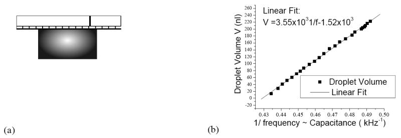
Droplet volume measurement on EWOD device. (a) Circuit model of capacitance between EWOD electrode and top ground electrode. (b) Capacitance measured by ring oscillator circuit vs. droplet volume on EWOD device. Excellent linear relationship and calibration were obtained.
There are many methods to measure capacitance. The method used by Ren et al. was chosen to measure the capacitance for feedback control [20], because its ring oscillator circuit can quickly measure capacitance in real time when high DC voltages are applied. In the ring oscillator circuit, a Hex Schmitt Trigger (MM74C14) generates the high frequency oscillation signal and its frequency is inversely proportional to the RC of the integral circuit. The EWOD device is coupled with an oscillation circuit with a capacitor to isolate the high-voltage (+80 V) actuation signal but pass the low-voltage (+5 V) high-frequency sensing signal. The oscillation frequency range can be modulated by changing resistance R to ensure high measurement resolution. A pulse counter in the microcontroller is used to measure the frequency of the pulse. Because the oscillation frequency is set between 1–3 MHz, the pulse counter receives 1000–3000 pulses in a 1 ms duration. The droplet volume was also measured optically by taking top-view pictures and calculating the footprint area using Scion Image®. The main error in image measurement is due to the uncertainty in determining the droplet edge by the software. The image resolution of our optical system is 2.5 μm/pixel at a maximum optical zoom (1.5 mm field of view for a picture of 800 × 600 pixels). Since the image processing software can distinguish no more than one pixel, the measurement error in the droplet area (approximately 1.5 mm × 1.5 mm) is estimated as 2.5 × 2 / 1500 = 0.333%. Fig. 3(b) shows excellent linearity between 1/frequency and the droplet volume. The measurement resolution is 1.9 nl/kHz. Within a 1 ms measurement time, the volume measurement error due to digital error is 0.84% for a 225 nl droplet. A higher measurement resolution may be achieved with a longer measurement time, however, this would compromise the speed of the feedback.
3.2 System hardware for the real-time feedback control
The speed requirement for the real-time control must be estimated before designing the real-time feedback control hardware. Because the droplet meniscus moves at a speed of 1–10 mm/s under 80–100 V EWOD actuation voltage, the droplet diameter can change as fast as 1–10 μm/ms (its volume changes 0.15–1.5 nl/ms). The voltage control hardware should update its outputs as fast as every 2 ms to achieve less than a 1% volume change for a 225 nl droplet during the droplet generation period. Faster updates would entail higher volume resolutions. On the other hand, the ring oscillator circuit prefers a longer measurement time to achieve better volume measurement resolution. In this work, the hardware was designed to update voltage outputs and measure droplet volume as fast as 1 ms in order to achieve actuation and sensing criteria for less than a 1% volume control precision for a 225 nl droplet.
Hardware for the real-time feedback control has been realized through a digital/analog mix signal circuit shown in Fig. 4. A microcontroller Microchip® PIC18F452 precisely outputs low analog voltages (0–3 V) through a 14-bit digital-analog-converter (Analog® AD7840) with microcontroller SPI interface. These signals are amplified by a 32-channel integrated circuit (IC) high voltage sample-and-hold amplifier array (Supertex® HV257) with 72 V/V amplifier gain. The high voltage output error is less than 0.5 V. By continually selecting 32 amplifier channels one by one and outputting low analog voltages through the microcontroller, different high voltages can be applied to the corresponding EWOD electrodes. The pulse counter port in the microcontroller is connected with a ring oscillator which measures capacitance on different EWOD electrode sites selected by a multiplexer, which is also controlled by the microcontroller. By using a fast 20 MHz microcontroller and optimizing the program code, one cycle of sensing and driving can be completed within 1 ms. The feedback control system parameters and algorithm can be easily programmed with a PC and downloaded into the microcontroller through on-board USB and IR wireless ports. Since most of the circuit components are small footprint IC chips, the whole operating circuit board including the feedback control capability has a size of 5” × 7” and may be further designed into a portable system using an advanced EWOD device package [21].
Figure 4.
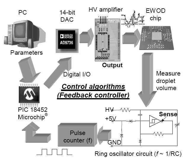
Diagram of discrete-time digital feedback control system hardware.
3.3 Control algorithms
Although Eq. (4) describes the relationship between the droplet volume and EWOD voltage during the droplet pinch-off process, the real process is much more complicated and highly nonlinear. A more sophisticated numerical solution may simulate this process [29], but the speed of currently available micro-processors does not allow such a large amount of calculation for real-time applications. Furthermore, in the current capacitance measurement method, only the droplet volume is deduced, and the full system information, such as the exact droplet shape, is missing. Note that a mathematical model cannot fully depict the uncertainties of surface condition and device variation in any case. For practical purpose and to simplify the feedback controller design, the system is treated as a black box with little information. Through experimental study, basic control algorithms were explored, by measuring the droplet volume dynamic responses but without making a detailed analysis, such as its stability, robustness, or system error.
A straightforward control algorithm can use proportional control as reported in [21]. If droplet volume in the creation site is less than the target volume, liquid should be pulled into the creation site; if it is more, liquid should be pumped out. The algorithm can be realized as follows. If the measured droplet volume v is less than v1, the reservoir site is turned off and the creation site is turned on; if v is larger than v2, the reservoir site is turned on and the creation site is turned off; if v is between v1 and v2, both the reservoir site and the creation site are turned on. The lower and upper volume limits (v1 and v2, respectively) correspond to the controlled droplet volume range, whose minimum is limited by resolution of the capacitance measurement. When the feedback control is stable and converges fast enough, less than 1% droplet volume precision can be expected by real-time feedback control.
To characterize the droplet volume change under the feedback control, the droplet dynamic response was recorded using a high speed camera (Phantom V6.5). As shown in Fig. 5(a), turning the reservoir on and the creation site off caused the droplet volume to rapidly decrease into the controlled range. Afterwards, the droplet volume still oscillated, but its amplitude gradually decreased until droplet pinch-off occurred within ± 2% volume variation. The large volume fluctuation is undesirable because the pinch-off time cannot be controlled well. Pinch-off may occur during this high fluctuation period and result in a large volume variation by a small shift of the pinch-off time. The real-time feedback control should converge as fast as possible to maintain a stable volume before the pinch-off. From the analysis in the previous section, we know the pressure difference between the separation site and the creation site can be regulated by the EWOD voltage at the creation site. A more sophisticated feedback controller can be designed with the creation site voltage U as control output and measurement capacitance C as control target. Since proportional control alone is not enough, integral and differential components were added into the feedback controller to improve the dynamic response, particularly for a large fluctuation. The discrete time proportional-integral-derivative (PID) feedback controller for the droplet volume control is:
Figure 5.
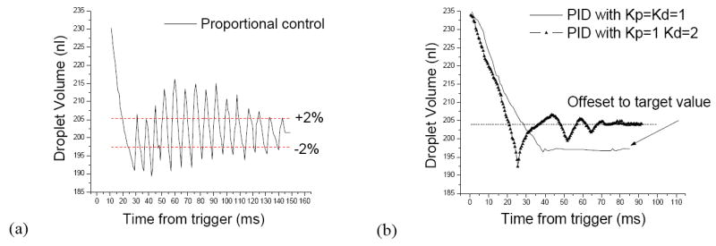
Droplet volume dynamic response (volume vs. time) under two different feedback controllers, using the same device and the same test conditions. (a) Under proportional control. (b) Under PID controller, using two different differential coefficients.
| (5) |
| (6) |
Here Un is the voltage output at tn, Cn is the measured capacitance, CT is the target capacitance, en is the error. Kp and Kd are proportional and differential coefficients, respectively. The integral coefficient Ki is always kept at 1 to ensure that the discrete time feedback control system is stable. We have experimentally explored different numbers of Kp and Kd and measured the droplet volume response. As the two typical cases show in Fig. 5(b), the dynamic response of the droplet volume has improved significantly under the PID controller. With a large Kd and a smaller Kp, the system tends to converge faster but generates a large error from the target value. By properly selecting Kd and Kp, the feedback controller can converge fast enough while keeping the system error small.
4. Experiment results and discussions
4.1 Continuous droplet generation
The developed feedback control was put to test by generating numerous droplets on the multi-layer PCB EWOD device with an air environment as the main interest. The electrode pattern is shown in Fig. 6(a). Some overlapping between electrodes are designed to help droplet movement. As shown in Fig. 6(b), typically 12 droplets were successively generated from one reservoir without replenishing it. Fig. 6(c) compares the droplet volume distribution with the feedback control and without (i.e., open loop), after running the operation of Fig. 6(b) multiple times on the same device. The experimental results show an improved volume precision with the feedback control. The standard deviation of the droplet volume distribution is 5 times less with feedback control than without, and the repeatability of the droplet volume is within ± 1%, which is satisfying for most biomedical applications. For DI water and low viscosity liquids, the whole on-chip droplet generation procedure including pulling liquid from the reservoir and cutting the droplet can be completed in 1–2 seconds. The dispensing rate can be as fast as 30 droplets/min from one generation site. On the multi-layer PCB EWOD device, a large two-dimensional array (16×16) has been fabricated, and multiple reservoirs were included on one device to achieve parallel operations and higher total dispensing rate [30].
Figure 6.
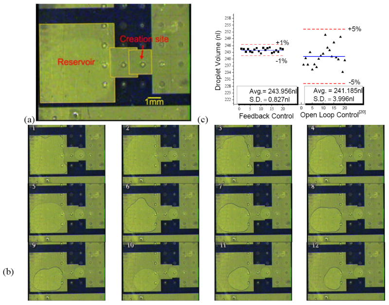
(a) Electrode pattern for droplet creation, (b) snapshots of 12 successive droplet generations from one reservoir, (c) comparison of droplet volume distribution between feedback and open loop controls.
Because the viscosity of the liquid will change the system characterization, especially the time constant, the viscosity effect has been investigated experimentally. Viscous solutions were made by mixing different concentrations of glycerin in the water solution. The standard deviation of the volume distribution for a 65% glycerin solution with 10 cP viscosity was 0.84 nl. For an 85% glycerin with 100 cP viscosity, the standard deviation was 1.32 nl. The volume distributions were in the same range as DI water, but the droplet pinch-off times were longer. It took longer than 5 seconds to cut 100 cP 85% glycerin, whereas only 100 ms was needed for 1 cP DI water.
Feedback control was also tested with the device filled with 1 cSt silicone oil. The standard deviation of DI water droplet was 2.93 nl in the oil-filled device, three times greater than in a dry device. This may be due to a droplet pinch-off occurring much faster in the oil-filled device. High-speed video showed that the pinch-off inside an oil-filled device can be as fast as 30 ms, and the liquid neck can break at the larger width. The deviations were also observed larger in the oil-filled device when the feedback control was not used. If an oil environment is essential but high precision is still required, droplets can be generated on a dry portion of the device and then transferred into the oil-filled section. Further improvements on hardware and the feedback control algorithm will also help to achieve better precision inside oil environment, such as improving feedback control to converge faster than 30 ms.
4.2 Variable droplet volume by feedback control
Feedback control will not only produce a more uniform droplet volume but also enable variable droplet volumes smaller than the previously considered minimum. Without feedback, the generated droplet must fill the full size of the patterned electrode, and the volume that can be achieved by adjusting voltages was limited to ± 10% volume change [23]. The minimum droplet size is determined by the size of the fabricated electrode, whose minimum size is in turn determined by the space height according to the droplet pinch-off criteria [18] i.e., ~900 μm diameter droplet for 100 μm channel height. With feedback control, on the other hand, the target droplet volume can be easily set by feedback control parameters. Experiments showed droplets as small as 750 μm can be generated on a 1.5 mm × 1.5 mm electrode in a device having a 100 μm channel height, covering only around 20% of the electrode area. A series of experiments have been conducted in which the target droplet volume was varied. Figs. 7(a)-(c) show the largest, medium, and smallest droplet sizes that could be generated by feedback control with an excellent linear relationship between the droplet volume and the control parameter 1/f ~ C shown in Fig. 7(d). With real-time feedback control, now a user can prescribe the volume during the droplet generation, not dictated by the electrode size anymore. The feedback control can also be applied to the droplet cutting process in a same fashion by setting one electrode as reservoir and another as creation site so that 1:x ratio droplet cutting (separating the droplet into different proportions) can be realized, where x is an arbitrary number between 0.2 and 1.
Figure 7.
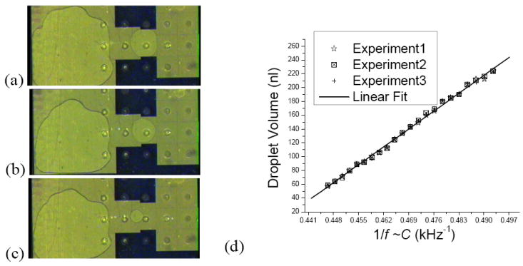
Snapshots right after droplet generation with three different set volumes. The created droplets occupy a varying portion of the creation electrode area (a) 100% (b) 65% (c) 20%. (d) linear relationship between created droplet volume and targeted capacitance C ~ 1/f.
With the new abilities to prescribe the droplet volume and perform 1:x cutting, we have devised a new dilution scheme for digital microfluidics. The solution dilution is important for sample preparation. In many bio applications, the solution concentrations may vary over several orders of magnitude [31]. In a simple dilution scheme with the droplets, the standard dilution factor in digital microfluidic is 2. As shown in Fig. 8(a), the solution and buffer droplets with equal volumes are mixed by bringing them together and then splitting the mixed droplet into two equal droplets, each with half the concentration of the original solution droplet [32]. A binary serial dilution of n cycles dilutes the sample by 2n, e.g., 14 cycles for 10000X dilution. Because concentration errors are introduced in every dilution cycle by droplet cutting, more dilution cycles lead to a larger error in the final concentration. If the droplet splitting can be 1:x and not just 1:1, on the other hand, a higher dilution factor per cycle can be realized. As depicted in Fig. 8(b), although a droplet smaller than the electrode cannot be further moved by EWOD, a buffer droplet of regular size may be brought to the solution droplet to merge. Afterwards, 1:x droplet cutting by feedback control may produce one small droplet with x/(x+1) of the concentration of the original solution droplet. The cycle of dilutions may be continued to further dilute the small droplet. The dilution factor by n cycles of dilution is ((x+1)/x)n. With 1:0.2 droplet cutting (i.e., x = 0.2), only 5 cycles are needed for 10000X dilution, in comparison to the 14 cycles needed for the binary dilution. Note another advantage is that a much smaller amount of diluting buffer is consumed. Feedback control also tames the final concentration error accumulated from the volume variation in each dilution step. With 10 cycles of 1:1 dilution to reach a 1000X dilution, the final concentration error can be over 20% in the worst-case scenario, too large for quantitative analysis. On the other hand, using a 1:0.2 droplet cutting and 10 dilution cycles, a 1000000X dilution can be achieved with the final concentration error less than 4% even in the worst case assuming we can achieve similar relative volume error for the 0.2 size droplet.
Figure 8.
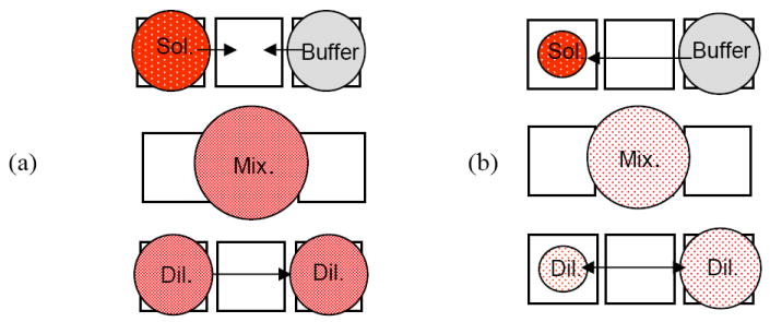
Comparison of one cycle of 1:1 (binary) and 1:x dilution. (a) 1:1 droplet mixing and cutting scheme for a 2X dilution, (b) 1:x droplet mixing and cutting for a (1+x)/x dilution.
5. Conclusions
Droplet generation is an essential step in most digital microfluidics, as a droplet is the basic unit of all its fluidic operations. A reliable operation is important because the volume of each droplet is determined in the generation step. An all-electronic method to generate droplets on chip allows a self-sufficient microfluidic chip with on-chip reservoirs and enables a compact and portable (even handheld) design of digital microfluidic system. We analyzed the droplet pinch-off processes during an on-chip droplet generation and determined the uncertainties. The results called for a fast and precise real-time feedback control approach. We have successfully designed and implemented hardware and software for the real-time feedback control, in combination with the on-chip droplet generation solely by EWOD actuation. The all electrical feedback control system demonstrates large potential for practical applications. The feedback brought about an improved uniformity of the droplet volume (5 times smaller standard deviation compared with open loop control). Furthermore, the feedback allowed the generation of varying volumes of droplets on a given electrode pattern. The former can improve device reliability by compensating for the uncertainties in the fabricated device and operation conditions, while the latter allows a new flexibility in fluidic operations such as a high-order solution dilution.
More sophisticated and advanced feedback control algorithms, supported by detailed modeling of the nonlinear droplet pinch-off process where still a lot researches need to be done, are expected to improve convergence speed, stability, system error and robustness of the control system. Through automatic system identification or neural network studies, the feedback controller may be improved in the future to self-calibrate for different solutions and devices without human intervention.
Acknowledgments
This work has been supported by the NASA Institute for Cell Mimetic Space Exploration (CMISE) at UCLA, NIH through Pacific Southwest RCE (grant AI065359), and a gift from Wendy and Ken Ruby.
Footnotes
Electronic Supplementary Information (ESI) available: [details of any supplementary information available should be included here]. See http://dx.doi.org/10.1039/b000000x/
References
- 1.Dittrich PS, Manz A. Lab-on-a-chip: microfluidics in drug discovery. Nature Reviews Drug Discovery. 2006:210–218. doi: 10.1038/nrd1985. [DOI] [PubMed] [Google Scholar]
- 2.Easley CJ, Karlinsey JM, Bienvenue JM, Legendre LA, Roper MG, Feldman SH, Hughes MA, Hewlett EL, Merkel TJ, Ferrance JP, Landers JP. A fully integrated microfluidic genetic analysis system with sample-in–answer-out capability. PNAS. 2006;103:19272–19277. doi: 10.1073/pnas.0604663103. [DOI] [PMC free article] [PubMed] [Google Scholar]
- 3.Vestad T, Marr DWM, Oakey J. Flow control for capillary-pumped microfluidic systems. Journal of Micromechanics and Microengineering. 2004;14:1503–1506. [Google Scholar]
- 4.Garstecki P, Fuerstman MJ, Stone HA, Whitesides GM. Formation of droplets and bubbles in a microfluidic T-junction - scaling and mechanism of break-up. Lab on a Chip. 2006;6:437–446. doi: 10.1039/b510841a. [DOI] [PubMed] [Google Scholar]
- 5.Kim C-J. Micromachines Driven by Surface Tension. Presented at AIAA 99-3800, 30th AIAA Fluid Dynamics Conference; Norfolk, VA. 1999. pp. 1–6. [Google Scholar]
- 6.Darhuber AA, Troian SM. Principles of microfluidic actuation by modulation of surface stresses. Annu Re Fluid Mecha. 2005;37:425–455. [Google Scholar]
- 7.Lee J, Kim C-J. Surface Tension Driven Microactuation Based on Continuous Electrowetting (CEW) J Microelectromech Syst. 2000;9:171–180. [Google Scholar]
- 8.Sammarco TS, Burns MA. Thermocapillary pumping of discrete drops in microfabricated analysis devices. AIChE J. 1999;45:350–366. [Google Scholar]
- 9.Jun TK, Kim C-J. Valveless Pumping using Traversing Vapor Bubbles in Microchannels. J Applied Physics. 1998;83:5658–5664. [Google Scholar]
- 10.Chaudhury MK, Whitesides GM. How to make water run uphill. Science. 1992;5063:1539–1541. doi: 10.1126/science.256.5063.1539. [DOI] [PubMed] [Google Scholar]
- 11.Guttenberg Z, Muller H, Habermuller H, Geisbauer A, Pipper J, Felbel J, Kielpinski M, Scriba J, Wixforth A. Planar chip device for PCR and hybridization with surface acoustic wave pump. Lab Chip. 2005:308–317. doi: 10.1039/b412712a. [DOI] [PubMed] [Google Scholar]
- 12.Nguyen N-T, Ng KM, Huang X. Manipulation of ferrofluid droplets using planar coils. Appl Phys Lett. 2006;89:052509. [Google Scholar]
- 13.Washizu M. Electrostatic actuation of liquid droplets for microreactor applications. IEEE Trans Ind Appl. 1998;34:732–737. [Google Scholar]
- 14.Shen W, Edwards RT, Kim C-J. Electrostatically-Actuated Metal-Droplet Microswitches Integrated on CMOS Chip. J Microelectromech Syst. 2006;15:879–889. [Google Scholar]
- 15.Schwartz JA, Vykoukal JV, Gascoyne PRC. Droplet-based chemistry on a programmable micro-chip. Lab Chip. 2004;4:11–17. doi: 10.1039/b310285h. [DOI] [PMC free article] [PubMed] [Google Scholar]
- 16.Pollack MG, Fair RB, Shenderov AD. Electrowetting-based actuation of liquid droplet for microfluidic applications. Appl Phys Lett. 2000;77:1725–1726. [Google Scholar]
- 17.Lee J, Moon H, Fowler J, Schoellhammer T, Kim C-J. Electrowetting and electrowetting-on dielectric for microscale liquid handling. Sens Actuators A. 2002;95:259–268. [Google Scholar]
- 18.Cho SK, Moon H, Kim C-J. Creating, transporting, cutting, and merging liquid droplets by electrowetting-based actuation for digital microfluidic circuits. J Microelectromech Syst. 2003;12:70–80. [Google Scholar]
- 19.Fair RB, Pollack MG, Woo R, Pamula VK, Ren H, Zhang T, Venkatraman J. A microwatt metal–insulator-solution-transport (MIST) device for scalable digital bio-microfluidic systems. Presented at IEEE International Electronic Device Meeting; Washington, DC, USA. 2001. pp. 367–370. [Google Scholar]
- 20.Ren H, Fair RB, Pollack MG. Automated on-chip droplet dispensing with volume control by electro-wetting actuation and capacitance metering. Sensors and Actuators B. 2004;98:319–327. [Google Scholar]
- 21.Gong J, Fan S-K, Kim C-J. Portable Digital Microfluidics Platform with Active but Disposable Lab-On-Chip. Presented at 17th IEEE International Conference on Micro Electro Mechanical Systems; Masstricht, Netherlands. 2004. pp. 355–358. [Google Scholar]
- 22.Gong J, Kim C-J. Two-dimensional digital microfluidic system by multi-layer printed circuit board. Presented at 18th IEEE International Conference on Micro Electro Mechanical Systems; Miami USA. 2005. pp. 726–729. [Google Scholar]
- 23.Gong J, Kim C-J. Characterization and design of digitizing processes for uniform and controllable droplet volume in EWOD digital microfluidics. Presented at Hilton Head 2006: A Solid State Sensors, Actuators and Microsystems Workshop; Hilton Head Island, SC, USA. 2006. pp. 159–162. [Google Scholar]
- 24.Gong J, Kim C-J. Real-time feedback control of droplet generation for EWOD digital microfluidics. Presented at The 10th International Conference on Miniaturized Systems for Chemistry and Life Sciences; Tokyo, Japan. 2006. pp. 1046–1048. [Google Scholar]
- 25.Gong J, Kim CJ. Direct-referencing two-dimensional-array digital microfluidics using multi-layer printed circuit board. J Microelectromech Syst. doi: 10.1109/JMEMS.2007.912698. Accepted. [DOI] [PMC free article] [PubMed] [Google Scholar]
- 26.Schiaffino S, Sonin AA. Formation and stability of liquid and molten beads on a solid surface. J Fluid Mech. 1997;343:95–110. [Google Scholar]
- 27.Jones TB, Gunji M, Washizu M, Feldman MJ. Dielectrophoretic liquid actuation and nanodroplet formation. J Appl Phys. 2001;89:1441–1448. [Google Scholar]
- 28.Constantin P, Dupont TF, Goldstein RE, Kadanoff LP, Shelley MJ. Droplet breakup in a model of the Hele-Shaw cell. Physical Review E. 1993;47:4169–4181. doi: 10.1103/physreve.47.4169. [DOI] [PubMed] [Google Scholar]
- 29.Walker SW, Shapiro B. Modeling the Fluid Dynamics of Electrowetting on Dielectric (EWOD) J Microelectromech Syst. 2006;15:986–1000. [Google Scholar]
- 30.Gong J. Mechanical Engineering. University of California; Los Angeles: 2007. Portable Digital Microfluidic System: Direct Referencing EWOD Devices and Operating Control Board; p. 130. [Google Scholar]
- 31.Lee A-Y, Chey W-Y, Choi J, Jeon J-S. Insulin-induced Drug Eruptions and Reliability of Skin Tests. Acta Derm Venereol. 2002;82:114–117. doi: 10.1080/00015550252948149. [DOI] [PubMed] [Google Scholar]
- 32.Ren H, Srinivasan V, Fair RB. Design and testing of an interpolating mixing architecture for electrowetting-based droplet-on-chip chemical dilution. Presented at International conference on solid state sensors, actuator and microsystems; Boston, MA, USA. 2003. pp. 619–622. [Google Scholar]