Abstract
Background
The glucose binding protein (GBP) is one of many soluble binding proteins found in the periplasmic space of gram-negative bacteria. These proteins are responsible for chemotactic responses and active transport of chemical species across the membrane. Upon ligand binding, binding proteins undergo a large conformational change, which is the basis for converting these proteins into optical biosensors.
Methods
The GBP biosensor was prepared by attaching a polarity-sensitive fluorescent probe to a single cysteine mutation at a site on the protein that is allosterically responsive to glucose binding. The fluorescence response of the resulting sensor was validated against high-performance anion-exchange chromatography (HPAEC) with pulsed electrochemical detection. Finally, a simple fluorescence reader was built using a lifetime-assisted ratiometric technique.
Results
The GBP assay has a linear range of quantification of 0.100–2.00 μM and a sensitivity of 0.164 μM−1 under the specified experimental conditions. The comparison between GBP and HPAEC readings for nine blind samples indicates that there is no statistical difference between the analytical results of the two methods at the 95% confidence level. Although the methods of fluorescence detection are based on different principles, the response of the homemade device to glucose concentrations was comparable to the response of the larger and more expensive tabletop fluorescence spectrophotometer.
Conclusions
A glucose binding protein labeled with a polarity-sensitive probe can be used for measuring micromolar amounts of glucose. Using a lifetime-assisted ratiometric technique, a low-cost GBP-based micromolar glucose monitor could be built.
Keywords: binding protein, biosensor, diabetes, glucose monitor
Introduction
Glucose sensing has important applications in bioprocess monitoring and diabetes care. Currently, available glucose sensors are mostly based on the enzyme glucose oxidase, and glucose oxidase-based sensors1–7 have glucose sensitivities usually in the millimolar range. As novel sampling techniques such as fast microdialysis,8 extraction of interstitial fluid by iontophoresis,9 and laser poration10,11 emerged in recent years, it has become necessary to develop new glucose sensors with submillimolar glucose sensitivities. Although still feasible, the submillimolar range is, in most cases, at the tail end of the sensitivities of glucose oxidase-based sensors.
The glucose binding protein (GBP) is one of many soluble binding proteins associated with adenosine 5′ triphosphate-binding cassette transporters. Naturally occurring binding proteins are found in the periplasmic space of gram-negative bacteria12–22, hence are called periplasmic binding proteins (PBPs). PBPs generally undergo a “close–open” conformational change with ligand binding. To utilize this conformational change to create an optical sensor, a polarity-sensitive fluorescent probe is attached to the protein at a site that is structurally linked to the ligand binding site. One way to realize this is to introduce a single cysteine mutation and then label the protein with a thiol-reactive polarity-sensitive probe. The MglB gene expressing the wild-type GBP from Escherichia coli K12 was cloned into vector pTU18Z. A single cysteine mutation at position 255 was introduced by site-directed mutagenesis, and the mutated protein was expressed in E. coli NM303. Acrylodan, a polarity-sensitive fluorescent probe, was attached to the cysteine at 255 using known chemical methods. The resulting glucose sensor has a responsive range at micromolar levels, which are the levels found in low glucose media, fast microdialysis samples, or human interstitial fluid extracted painlessly by iontophoresis. Thus, this optical sensor is a valuable supplement to currently available glucose oxidase-based sensors. Additionally, adaptation to a continuous glucose monitoring system in combination with the novel extraction technologies as described is evident.
As a caveat, GBP also binds galactose. Nevertheless, the sensitivity of GBP to galactose is at a lower affinity than for glucose.18 Thus, galactose interference may be considered negligible in most situations. Exceptions include patients with galactosemia and some newborns, whose blood contains elevated galactose (6–10 mg/dl). GBP is essentially insensitive to other sugars.
In previous studies, several binding protein mutants were prepared and labeled with different polarity sensitive probes.17–21 It was shown that these proteins have a number of desirable properties, such as high sensitivity and good selectivity, and thus can be used for highly sensitive assays. Here, we validated the GBP-based fluorescence assay against high-performance anion-exchange chromatography (HPAEC) with pulsed electrochemical detection (PED) as the standard method. HPAEC-PED was used as a standard for validation because it has been in use for several decades23,24 and is a highly accepted method in the determination of sugars. It provides excellent sensitivity and selectivity for carbohydrates and other electroactive species. Results show that the GBP assay method is closer in its range of quantification to HPAEC-PED under specified experimental conditions than the more prevalent but less sensitive glucose oxidase electrochemical methods. In addition, no statistical difference was found between the analytical results of GBP and HPAEC methods.
Upon validation of the GBP-based fluorescence assay, we proceeded to build a small low-cost glucose monitor. The purpose of building this small GBP-based device was to explore the possibility of a portable glucose monitor for field and point-of-care use. The low-cost laboratory-made glucose monitor was constructed completely from inexpensive electronics and optics. Additionally, the dimensions are significantly smaller than a bench-sized fluorescence spectrophotometer. Because low-cost instrumentation comes with limitations not encountered in the more expensive fluorescence spectrophotometers, the biosensor itself was modified to improve the accuracy, precision, and overall user-friendliness of the prototype. The GBP was labeled with a second fluorophore,21 allowing for ratiometric measurement of intensities. This strategy prevents systematic sources of error such as fluctuations in intensity of the light source, temperature, interference by ambient light, and distance variations of sample to excitation light and photodetector, as well as photobleaching. Furthermore, separation of the fluorescence intensities of the two fluorophores was achieved not by the use of multiple filters, but by a lifetime-assisted ratiometric technique. Here we show that although the cost of this fluorescence reader is only $100 or less, its response to glucose concentration is comparable to the more expensive Varian Cary spectrophotometer.
As the glucose sensor discussed in this article has micromolar sensitivity for glucose, it is not intended for measuring blood samples directly, which have millimolar glucose concentrations. Instead, the glucose sensor discussed here can be used in conjunction with novel sampling techniques such as microdialysis and interstitial fluid extraction by iontophoresis. The glucose concentration in the interstitial fluid extract is 0–30 μM,9 which is the responsive range of the glucose sensor discussed here. Additionally, we are in the process of preparing a manuscript describing the use of microdialysis in combination with the GBP sensor. These preliminary results should lead to a continuous glucose monitoring system.
Materials
6-Acryloyl-2-dimethylaminonaphthalene (acrylodan) and tris(2-carboxyethyl)phosphine were purchased from Molecular Probes (Eugene, OR). Fucose, sucrose, glucose, DEAE Sephadex A-50, N,N-dimethylformamide, NaCl, KH2PO4, Na2HPO4, NaH2PO4, and MgCl2 were purchased from Sigma-Aldrich (St. Louis, MO). Tryptone and yeast extract were obtained from Becton Dickinson (Sparks, MD). All chemicals were used without further purification. Slide-A-lyzer® dialysis cassettes were purchased from Pierce (Rockford, IL). Bis(2,2′-bipyridine) (5-isothiocyanato-phenanthroline) ruthenium II(hexafluorophosphate) [Ru(bpp)] was prepared as reported previously.25
Methods
Protein Expression, Purification, and Fluorophore Coupling
The plasmid JL01 expressing the wild-type GBP, which has no cysteine, was prepared by cloning the E. coli K12 MglB gene into vector pTU18Z. To label the protein with an environmentally sensitive thiol-reactive probe, plasmid JL01 encoding for the wild-type GBP was mutated using the Quick-Change mutagenesis kit from Stratagene (Cedar Creek, TX). The choice of the site for mutation is generally based on the identification of specific sites that undergo maximum conformational change upon substrate binding.15 As different environment-sensitive probes conjugated to the same site often show varying responses to analyte concentrations, it is usually necessary to test several different probes, and the one showing maximal signal change is selected. The L255C GBP mutant used in experiments has a single cysteine mutation at position 255 where acrylodan was labeled. For dual-emitting binding proteins, the long-lived environmentally insensitive ruthenium dye Ru(bpp) was attached to the N terminus amino group by pH selection. Upon ligand binding, the environmentally sensitive acrylodan was exposed to the solvent, resulting in a decrease in its fluorescence intensity. However, the luminescence intensity of the long-lived Ru(bpp) was unaffected, thereby acting as a reference. Expression, release, and purification of the L255C mutant, as well as the labeling of acrylodan and Ru(bpp), were as described previously.17–21
Preparation of Glucose Standards
The glucose standard solutions were prepared from D glucose (>99.5% purity) obtained from Sigma-Aldrich. Volumetric flasks were used to make the stock solution (1000 μM) and the following dilutions: 50, 100, 200, and 400 μM. The water used to make standard solutions was purified using a reverse osmosis system coupled with a multitank/ultraviolet/ultrafiltration station (US Filter/Ionpure, Lowell, MA).
Fluorescence Measurements
Fluorescence intensities were measured on a Varian Cary eclipse fluorescence spectrophotometer (Varian Instruments, Walnut Creek, CA). Five hundred microliters of GBP solution (3.0 μM) was added to a 1.5 ml polymethylmethacrylate cuvette (BrandTech Scientific, Essex, CT). Then 5.0 μl of glucose solution was added, the mixture was vortexed gently for 10 seconds, and the cuvette was then placed on the spectrophotometer for fluorescence measurement. The assay was performed in triplicate for each solution. All measurements were made at the same instrumental conditions: excitation wavelength 380 nm, emission wavelength 510 nm, excitation slit width 5 nm, emission slit width 5 nm, photomultiplier tube (PMT) detector voltage 750 volts, and average time 0.1 seconds.
High-Performance Anion-Exchange Chromatography and Pulsed Electrochemical Detection
A DX-500 microbore liquid chromatography system (Dionex Corporation, Sunnyvale, CA) with a Dionex Model ED40 electrochemical cell and pulsed electrochemical detector was used for the validation of GBP. The electrochemical detector was equipped with an Au electrode, a combination pH and Ag/AgCl reference electrode, and a titanium auxiliary electrode. Separation was achieved using a Dionex CarboPac PA10 guard and PA10 2 × 250-mm analytical column. The mobile phase was 0.150 M NaOH, which was delivered isocratically. All solvents were degassed and kept under pressure (N2, ∼10 psi). Samples were diluted 1:10 in water to be in the linear range of the instrument and were introduced by an AS3500 autosampler (Spectra-Physics, Mountain View, CA) onto an injection valve (Model 9010, Rheodyne, Inc., Cotati, CA) fitted with a 25-μl injection loop. Glucose was analyzed using a pulsed potential waveform controlled by Peaknet software (Dionex, Version 5.21). Under the experimental conditions, glucose elutes in 4.3 minutes. Samples were run in triplicate; the glucose concentration in the solution was quantified using peak area data from the chromatogram.
Low-Cost Laboratory-Made Fluorescence Reader
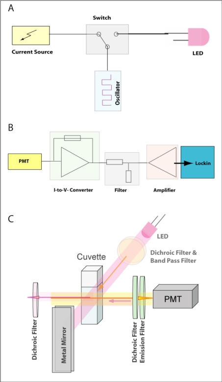
The prototype for the low-cost laboratory-made device shown in Figure 1 is composed of electronics and optics components. Electronics include a light-emitting diode (LED) driving circuit (Figure 1A) and a signal processing circuit (Figure 1B). The LED (RL5-UV2030, Superbrightleds, St. Louis, MO) is driven by a current source providing the LED with more than 100 mA. In order to modulate the LED light source, the current source (NUD4001, ON Semiconductor, East Greenwich, RI) is connected to a switch (ADG736, Analog Devices, Norwood, MA), which is alternately turned on and off by a square wave generator (LTC6902, Linear Technology, Milpitas, CA). In addition, a further switch allows the user to choose between two frequencies of 30 kHz and 3 MHz. The signal-processing unit (Figure 1B) consists of a transimpedance amplifier, which converts the PMT (Hamamatsu, Bridgewater, NJ) current signal into a voltage signal. It is then filtered and preamplified (OPA129, Texas Instruments) prior to passing to the external lock-in amplifier where the modulated signal is isolated from noise demodulation. The demodulated signal can be read out manually or further processed by a computer. The optics comprises a LED (Superbrightleds) as the light source, a PMT (Hamamatsu) as the photodetector, and a standard cuvette as the cell holder. The light source and photodetector are positioned perpendicularly to each other. In order to minimize signal loss, a new approach comprising a series of dichroic mirrors is designed. The excitation light is filtered by a band-pass filter (Intor, New Mexico) and a dichroic filter (Unaxis, Balzer, Liechtenstein), which reflects the fluorescence light (orange beam in Figure 1C) back to the cuvette. In order to minimize the optical signal loss, a dichroic filter is placed on the side of the cuvette opposite to the PMT. Its function is to reflect the fluorescence signal back to the PMT while letting the excitation light (violet beam) pass through. In this way, excitation light entering the detector is kept at a minimum level and the fluorescence signal is increased. On the opposite side of the LED, a metal mirror is positioned that reflects both the fluorescence and the excitation light back to the cuvette, maximizing the excitation light flux.
Figure 1.
The LED driving circuit (A), signal processing circuit (B), and optical setup (C) of the low-cost laboratory-made glucose monitor.
Results and Discussion
Emission spectra of GBP labeled with acrylodan in the presence of glucose are shown in Figure 2. Glucose concentrations in the standards, from top to bottom, were 0, 50.00, 100.0, 200.0, 400.0, and 1000 μM, respectively. Volumes of 5.00 μl of these standards were added to a 500.0-μl protein solution. Thus, final total glucose concentrations in the assay, including bound and free glucose, were 0, 0.500, 1.00, 2.00, 4.00, and 9.90 μM. Consistent with past results,18,20,21 the fluorescence intensity of the labeled acrylodan decreased with increasing glucose concentrations. Concurrently, the maximum emission wavelength red shifted from 506 to 514 nm. To simplify the assay, the average of emission maxima at different glucose concentrations (i.e., 510 nm) was used for all measurements. The inset in Figure 2 shows normalized fluorescence intensity at this wavelength and its change relative to the blank at different glucose concentrations. The signal change was used for comparison with HPAEC-PED readings so that both methods show a trend of increasing response with increasing amounts of glucose.
Figure 2.
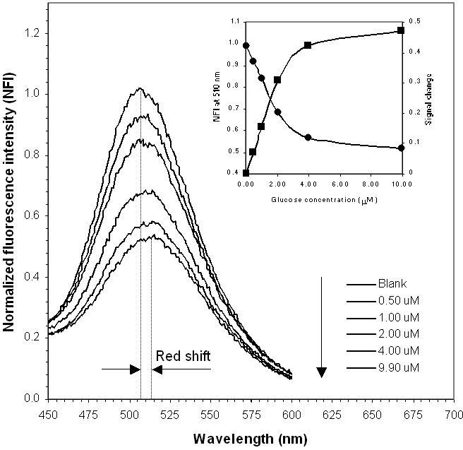
Normalized emission spectra of GBP labeled with acrylodan excited at 380 nm in increasing concentrations of glucose. GBP concentration: 3 μM. (Inset) Normalized fluorescence intensity at 510 nm and signal change with glucose concentration. Data were obtained on a Varian fluorescence spectrophotometer.
Calibration curves for both HPAEC-PED and GBP are shown in Figure 3. Although GBP data are often fitted to the binding isotherm,22 in analytical applications it is more convenient to use the most sensitive part of the response and fit calibration data to a linear equation, which is shown in Figure 3. The average deviation of GBP experimental data in the range of 0.10–2.00 μM from the linear equations shown in Figure 3 is 6%. The sensitivity of the method within this linear responsive range is indicated by the slope of the equation, which is 0.164 μM1, as shown in Figure 3.
Figure 3.
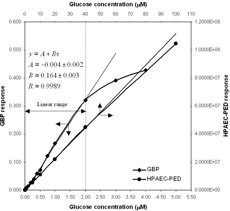
Calibration curves for both GBP and HPAEC. Sample sizes are 5.00 μl for GBP and 25.0 μl for HPAEC. The average deviation of experimental data for GBP from linear equations is 6% (0.10–2.00 μM).
The limit of detection26 (LOD) for glucose by HPAEC-PED is 0.005 μM with a 25-μl injection loop. This limit of detection in clean, buffered solutions of glucose is achieved because of the low level of noise, as shown in a representative HPAEC chromatogram of 5.66 μM glucose in Figure 4. The linear range for HPAEC in Figure 3 is 0.02–40 μM. The LOD and the limit of quantification (LOQ) for the GBP method are relatively higher because of the higher level of inherent noise (Figure 5). These two parameters were calculated to be 0.10 and 0.40 μM, respectively. However, as the duration of a single fluorescence intensity read is only 0.1 seconds, many reads can be made and averaged (as shown in Figure 5) in the same time it takes to do an HPAEC analysis. When the GBP signal was averaged per 10 reads, the LOD and LOQ were reduced from 0.10 and 0.40 μM to 0.04 and 0.10 μM, respectively. When the GBP signal was averaged per 100 reads, the LOD and LOQ were further reduced to 0.02 and 0.05 μM, respectively. Although these values do not approach the sensitivity of HPAEC-PED, they are more than acceptable for most applications.
Figure 4.
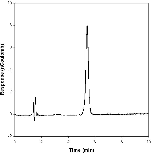
HPAEC-PED chromatogram of 1 ppm (5.66 μM) glucose standard, single injection.
Figure 5.
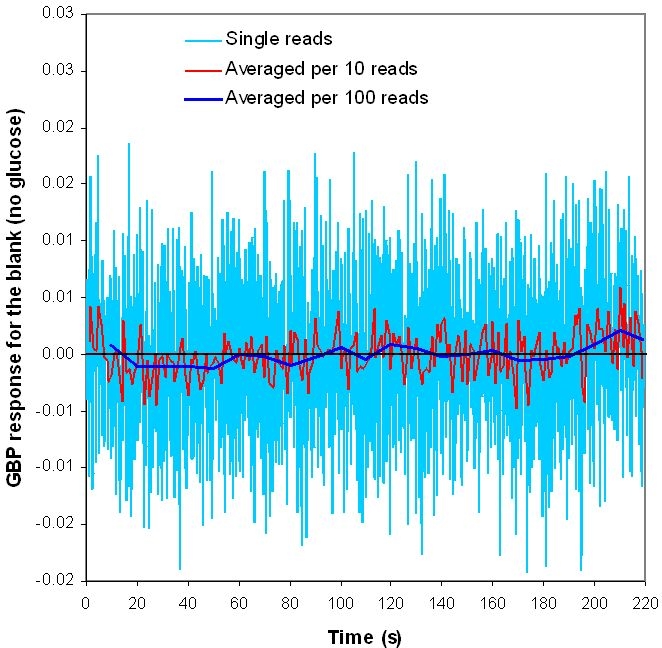
GBP response for the blank (no glucose). The duration for a single read is only 0.1 seconds.
It should be noted that the linear range of quantification for the GBP method shown in Figure 3 is dependent on the GBP concentration. The upper linear responsive limit is proportional to the GBP concentration, whereas the sensitivity is inversely proportional to it. Regardless of the GBP concentration, the yield of the two parameters, upper linear responsive limit and sensitivity, is a constant.
Figure 6 and Table 1 show comparisons between true values and GBP and HPAEC readings for nine blind glucose samples and comparisons between the two methods. For the HPAEC method, the glucose concentration in the samples was quantified by using peak area data and the response factors of bracketing standards. For the GBP method, the reported fluorescence intensity was the average of 20 readings. All samples were analyzed in triplicate for both methods. Figure 6 shows that the two different methods gave very similar results. Table 1 shows that at the 95% confidence level, no significant differences exist between true values and GBP data except for the two samples with lowest glucose concentrations (25.0 and 40.0 μM). Note that the actual concentrations of these samples in the assay are 0.25 and 0.40 μM after 1:100 dilution of the standard protein solution. Because 0.25 and 0.40 μM are close to the LOQ of the GBP-based glucose assay (0.10 μM), it is difficult to obtain satisfactory readings at these low glucose concentrations. However, it is reasonable to assume that had a 1:50 dilution been done, the glucose concentrations of the samples would have been determined satisfactorily. To compare the GBP-based assay with the HPAEC, an F test was performed on the standard deviations of the two data sets. A Student's t test was performed using the mean and the pooled standard deviation. Results show that the two data sets are not statistically different at the 95% confidence level.
Figure 6.
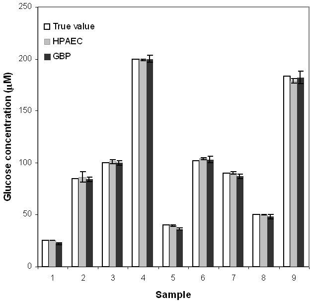
Comparison between true glucose concentrations in nine blind samples and their GBP and HPAEC readings.
Table 1.
Statistical Analysis of Glucose Concentrations Determined by GBP and HPAEC27
| HPAEC (Method 1) | GBP (Method 2) | F test | ||||
|---|---|---|---|---|---|---|
| Sample | True value (μM) | Concentration (μM) | 95% confidence test vs true value (t = 4.30) | Concentration (μM) | 95% confidence test vs true value (t = 4.30) | Method 1 vs Method 2 |
| 1 | 25.0 | 25.2 ± 0.1 | Pass | 22 ± 1 | Fail | Pass |
| 2 | 85.0 | 86 ± 5 | Pass | 84 ± 2 | Pass | Pass |
| 3 | 100 | 101 ± 2 | Pass | 100 ± 2 | Pass | Pass |
| 4 | 200 | 199.0 ± 0.5 | Pass | 200 ± 3 | Pass | Pass |
| 5 | 40.0 | 39.4 ± 0.7 | Pass | 36 ± 1 | Fail | Pass |
| 6 | 102 | 104 ± 1 | Pass | 103 ± 3 | Pass | Pass |
| 7 | 90.0 | 90 ± 1 | Pass | 87 ± 2 | Pass | Pass |
| 8 | 50.0 | 49.8 ± 0.5 | Pass | 48 ± 2 | Pass | Pass |
| 9 | 183 | 179 ± 2 | Pass | 182 ± 6 | Pass | Pass |
The validation experiments described previously where the GBP-based fluorescence assay was compared to HPAEC-PED as the standard method was done using clean, buffered solutions of glucose. Attempts to carry out the comparison in complex samples such as culture media proved to be more difficult because of the large background signal in HPAEC-PED generated by other sample components (data not shown). With the GBP-based assay, previous work has shown that the presence of a large number of components in a sample does not pose a major interference problem.18 This is because the binding proteins have evolved to recognize only their ligands even in a very complex mixture. Thus, GBP responds only to glucose (and to a lesser extent to galactose) even when other sugars and similar compounds are present. Additionally, most samples of biomedical or biotechnological importance have glucose concentrations that require a dilution step to be within the sensitivity range of the GBP assay. As an example, blood glucose levels are in the millimolar levels and require a dilution step to reduce glucose concentrations to the micromolar range. A positive consequence of the dilution step is a decrease in the interfering autofluorescence signal associated with the other components (e.g., blood proteins) while the glucose concentration is adjusted to be within the detection range of GBP. Minimally invasive sampling techniques such as microdialysis and iontophoresis that inherently dilute the sample are therefore especially suited for the micromolar sensitivity of the GBP assay.
Because the aforementioned results were encouraging, we explored the possibility of building a small low-cost device that uses the GBP-based fluorescence assay for point-of-care and field glucose monitoring. Considering that the intensity measurements made on a low-cost device may not be as stable as those made on the more expensive Varian fluorescence spectrophotometer, we started by modifying the GBP fluorescence properties so that it became amenable to low-cost instrument design. Thus, in addition to the polarity-sensitive fluorophore (acrylodan) labeled at the single cysteine mutation, we introduced a second fluorophore that serves as an internal reference. The long-lived metal–ligand complex Ru(bpp) was attached to the N-terminal of the protein specifically for this purpose. While the fluorescence intensity of acrylodan changes in response to glucose binding, the fluorescence intensity of Ru(bpp) is not affected. Consequently, Ru(bpp) serves as an internal reference in ratiometric measurements that are less susceptible to systematic errors than intensity measurements alone.
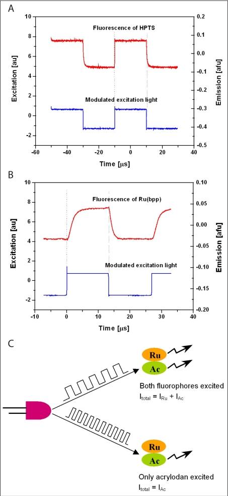
Another rationale for the choice of Ru(bpp) is its longer decay lifetime than acrylodan [lifetime of acrylodan <3 ns, Ru(bpp) >300 ns]. Unlike the Varian spectrophotometer, which directly measures the fluorescence intensity of different fluorophores at the corresponding maximal emission wavelength, the laboratory-made device utilizes the difference of the fluorophores' lifetimes to separate their fluorescence intensities. When the dual-labeled GBP is excited by a step signal, the fluorescence of the short-lived fluorophore increases quickly and reaches its maximum almost immediately (Figure 7A). Here we used HPTS as an example for the short-lived fluorophore as it has similar emission and excitation wavelengths and decay lifetime as acrylodan. Comparatively, the emission of Ru(bpp) responds much more slowly (Figure 7B). Thus, Ru(bpp) is not efficiently excited and, therefore, unable to fluoresce if the excitation light pulse is very short (Figure 7C). Here, we used square wave light with two different modulation frequencies (30 kHz, pulse length 16.7 ms; 2.1 MHz, pulse length 238 ns) to excite the dual-labeled GBP. When excited by the high-frequency light, only acrylodan fluoresces. In contrast, the low-frequency light excites both fluorophores. Therefore, the fluorescence of both dyes can be differentiated effectively by alternating the excitation pulse length.
Figure 7.
Fluorescence of HPTS (A) and Ru(bpp) (B) in response to a square wave excitation light source. (C) Principle of lifetime-assisted signal separation.
Figure 8A shows fluorescence intensities of the dual-labeled GBP measured on the low-cost laboratory-made glucose monitor at 30 kHz and 2.1 MHz, and the ratio of IAc/IRu in increasing glucose concentrations. The emission at 30 kHz is much higher than at 2.1 MHz, as both Ru(bpp) and acrylodan are excited at the lower frequency. However, Ru(bpp) is not excited and thus does not fluoresce at the higher frequency. Figure 8B shows the comparison between readings of the laboratory-made device and the Varian spectrophotometer. Although the mechanisms for intensity measurement are quite different, it is clear that the low-cost laboratory-made glucose monitor gives comparable results to the expensive Varian spectrophotometer. Further experiments to optimize the low-cost glucose monitor and to miniaturize the optoelectronics and fluidics to the size of a hand-held device are currently ongoing.
Figure 8.
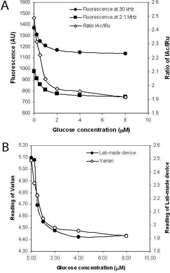
(A) Emission intensities measured by the low-cost glucose monitor at two different modulation frequencies (30 kHz and 2.1 MHz) and the ratios of IAu/IRu in increasing concentrations of glucose. (B) Comparison between readings of the laboratory-made device and the Varian spectrophotometer.
Acknowledgement
The E. coli NM303 was from cultures originally provided by Dr. W. Boos, University Konstanz, Germany.
Abbreviations
- GBP
glucose binding protein
- HPAEC
high-performance anion-exchange chromatography
- LED
light-emitting diode
- LOD
limit of detection
- LOQ
limit of quantification
- PBPs
periplasmic binding proteins
- PED
pulsed electrochemical detection
- PMT
photomultiplier tube
- Ru(bpp)
Bis(2,2'-bipyridine)-(5-isothiocyanato-phenanthroline) ruthenium II(hexafluorophosphate)
References
- 1.Miscoria SA, Desbrieres J, Barrera GD, Labbé P, Rivas GA. Glucose biosensor based on the layer-by-layer self-assembling of glucose oxidase and chitosan derivatives on a thiolated gold surface. Anal Chim Acta. 2006;578(2):137–144. doi: 10.1016/j.aca.2006.06.060. [DOI] [PubMed] [Google Scholar]
- 2.Mignani A, Scavetta E, Tonelli D. Electrodeposited glucose oxidase/anionic clay for glucose biosensors design. Anal Chim Acta. 2006;577(1):98–106. doi: 10.1016/j.aca.2006.06.041. [DOI] [PubMed] [Google Scholar]
- 3.Endo H, Yonemori Y, Musiya K, Maita M, Shibuya T, Ren H, Hayashi T, Mitsubayashi K. A needle-type optical enzyme sensor system for determining glucose levels in fish blood. Anal Chim Acta. 2006;573–574:117–124. doi: 10.1016/j.aca.2006.04.068. [DOI] [PubMed] [Google Scholar]
- 4.Kang X, Mai Z, Zou X, Cai P, Mo J. A novel glucose biosensor based on immobilization of glucose oxidase in chitosan on a glassy carbon electrode modified with gold-platinum alloy nanoparticles/multiwall carbon nanotubes. Anal Biochem. 2007;369(1):71–79. doi: 10.1016/j.ab.2007.07.005. [DOI] [PubMed] [Google Scholar]
- 5.Dai Z, Fang M, Bao J, Wang H, Lu T. An amperometric glucose biosensor constructed by immobilizing glucose oxidase on titanium-containing mesoporous composite material of no. 41 modified screen-printed electrodes. Anal Chim Acta. 2007;591(2):195–199. doi: 10.1016/j.aca.2007.03.063. [DOI] [PubMed] [Google Scholar]
- 6.Ekanayake EM, Preethichandra DM, Kaneto K. Polypyrrole nanotube array sensor for enhanced adsorption of glucose oxidase in glucose biosensors. Biosens Bioelectron. 2007;23(1):107–113. doi: 10.1016/j.bios.2007.03.022. [DOI] [PubMed] [Google Scholar]
- 7.Henninger N, Woderer S, Kloetzer HM, Staib A, Gillen R, Li L, Yu X, Gretz N, Kraenzlin B, Pill J. Tissue response to subcutaneous implantation of glucose-oxidase-based glucose sensors in rats. Biosens Bioelectron. 2007;23(1):26–34. doi: 10.1016/j.bios.2007.03.016. [DOI] [PubMed] [Google Scholar]
- 8.Heinemann L. Continuous glucose monitoring by means of the microdialysis technique: underlying fundamental aspects. Diabetes Technol Ther. 2003;5(4):545–561. doi: 10.1089/152091503322250578. [DOI] [PubMed] [Google Scholar]
- 9.Sieg A, Guy RH, Delgado-Charro MB. Noninvasive glucose monitoring by reverse iontophoresis in vivo: application of the internal standard concept. Clin Chem. 2004;50(8):1383–1390. doi: 10.1373/clinchem.2004.032862. [DOI] [PubMed] [Google Scholar]
- 10.Gebhart S, Faupel M, Fowler R, Kapsner C, Lincoln D, McGee V, Pasqua J, Steed L, Wangsness M, Xu F, Vanstory M. Glucose sensing in transdermal body fluid collected under continuous vacuum pressure via micropores in the stratum corneum. Diabetes Technol Ther. 2003;5(2):159–166. doi: 10.1089/152091503321827812. [DOI] [PubMed] [Google Scholar]
- 11.Burdick J, Chase P, Faupel M, Schultz B, Gebhart S. Real-time glucose sensing using transdermal fluid under continuous vacuum pressure in children with type 1 diabetes. Diabetes Technol Ther. 2005;7(3):448–455. doi: 10.1089/dia.2005.7.448. [DOI] [PubMed] [Google Scholar]
- 12.Tian Y, Cuneo MJ, Changela A, Hocker B, Beese LS, Hellinga HW. Structure-based design of robust glucose biosensors using a Thermotoga maritima periplasmic glucose-binding protein. Protein Sci. 2007;16(10):2240–2250. doi: 10.1110/ps.072969407. [DOI] [PMC free article] [PubMed] [Google Scholar]
- 13.Cuneo MJ, Changela A, Warren JJ, Beese LS, Hellinga HW. The crystal structure of a thermophilic glucose binding protein reveals adaptations that interconvert mono and di-saccharide binding sites. J Mol Biol. 2006;362(2):259–270. doi: 10.1016/j.jmb.2006.06.084. [DOI] [PubMed] [Google Scholar]
- 14.Ye K, Schultz JS. Genetic engineering of an allosterically based glucose indicator protein for continuous glucose monitoring by fluorescence resonance energy transfer. Anal Chem. 2003;75:3451–3459. doi: 10.1021/ac034022q. [DOI] [PubMed] [Google Scholar]
- 15.Marvin JS, Hellinga HW. Engineering biosensors by introducing fluorescent allosteric signal transducers: construction of a novel glucose sensor. J Am Chem Soc. 1998;120:7–11. [Google Scholar]
- 16.Salins LL, Ware RA, Ensor CM, Daunert S. A novel reagentless sensing system for measuring glucose based on the galactose/glucose-binding protein. Anal Biochem. 2001;294(1):19–26. doi: 10.1006/abio.2001.5131. [DOI] [PubMed] [Google Scholar]
- 17.Tolosa L, Gryczynski I, Eichhorn LR, Dattelbaum JD, Castellano FN, Rao G, Lakowicz JR. Glucose sensor for low-cost lifetime based sensing using a genetically engineered protein. Anal Biochem. 1999;267:114–120. doi: 10.1006/abio.1998.2974. [DOI] [PMC free article] [PubMed] [Google Scholar]
- 18.Ge X, Tolosa L, Simpson J, Rao G. Genetically engineered binding proteins as biosensors for fermentation and cell culture. Biotechnol Bioeng. 2003;84(6):723–731. doi: 10.1002/bit.10830. [DOI] [PubMed] [Google Scholar]
- 19.Tolosa L, Ge X, Rao G. Reagentless optical sensing of glutamine using a dual-emitting glutamine-binding protein. Anal Biochem. 2003;314(2):199–205. doi: 10.1016/s0003-2697(02)00586-9. [DOI] [PubMed] [Google Scholar]
- 20.Ge X. Baltimore County: University of Maryland; 2004. Development of novel optical sensors for fermentation and cell culture [dissertation] [Google Scholar]
- 21.Ge X, Tolosa L, Rao G. Dual-labeled glucose binding protein for ratiometric measurements of glucose. Anal Chem. 2004;76(5):1403–1410. doi: 10.1021/ac035063p. [DOI] [PubMed] [Google Scholar]
- 22.Dattelbaum JD, Lakowicz JR. Optical determination of glutamine using a genetically engineered protein. Anal Biochem. 2001;291:89–95. doi: 10.1006/abio.2001.4998. [DOI] [PMC free article] [PubMed] [Google Scholar]
- 23.Hughes S, Johnson DC. Amperometric detection of simple carbohydrates at platinum electrodes in alkaline solutions by application of a triple-pulse potential waveform. Anal Chim Acta. 1981;132:11–22. [Google Scholar]
- 24.LaCourse WR. New York: Wiley; 1997. Pulsed electrochemical detection in high performance liquid chromatography. [Google Scholar]
- 25.Youn HJ, Terpetschnig E, Szmacinski H, Lakowicz JR. Fluorescence energy transfer immunoassay based on a long-lifetime luminescent metal-ligand complex. Anal Biochem. 1995;232:24–30. doi: 10.1006/abio.1995.9966. [DOI] [PMC free article] [PubMed] [Google Scholar]
- 26.Long GL, Winefordner JD. Limit of detection—a closer look at the IUPAC definition. Anal Chem. 1983;55(7):712A–714A. [Google Scholar]
- 27.Skoog DA, Holler FJ, Nieman TA. 5th ed 1998. Principles of instrumental analysis. [Google Scholar]


