Abstract
The X-ray crystallographic structure of cellulose IIIII is characterized by disorder; the unit cell (space group P21; a=4.45Å, b=7.64Å c=10.36Å, α=β=90°, γ=106.96°) is occupied by one chain that is the average of statistically disordered antiparallel chains. 13C CP/MAS NMR studies reveal the presence of three distinct molecular conformations that can be interpreted as a mixture of two different crystal forms, one equivalent to cellulose IIII, and another with two independent glucosyl conformations in the asymmetric unit. Both X-ray crystallographic and 13C NMR spectroscopic results are consistent with an aggregated microdomain structure for cellulose IIIII. This structure can be generated from a new crystal form (space group P21; a=4.45Å, b=14.64Å c=10.36Å, α=β=90°, γ=90.05°; two crystallographically independent and antiparallel chains; gt hydroxymethyl groups) by multiple dislocation defects. These defects produce microdomains of the new crystal form and cellulose IIII that scanning microprobe diffraction studies show are distributed consistently through the cellulose IIIII fiber.
Introduction
The treatment and processing of cellulose and cellulosic biomass with amines has been studied and developed for many years now.1-8 Amines can act as swelling agents, penetrating fibers and forming crystalline complexes with cellulose, some of which can be relatively stable. On removal of amines, the fibers have improved pulping and textile properties, and an increased susceptibility to cellulase digestion during biomass conversion for biofuels. 9-22 In order to understand the detailed interaction of amines with cellulose and cellulosic biomass fibers, we have been studying these interactions using a variety of crystallographic and spectroscopic techniques.
In previous studies we described in atomic detail the action of the amines ammonia and ethylenediamine (EDA) on the naturally occurring crystal forms of cellulose, Iα and Iβ, 23-26 which are collectively called cellulose I. Both treatments transform cellulose I into intermediate crystalline amine-cellulose I complexes 27-29 and then, on removal of amines, into cellulose IIII, 30, 31 a crystal form of cellulose which is highly activated for hydrolysis by cellulases.32 On hydrothermal treatment cellulose IIII is transformed back to cellulose Iβ.33 The Iα phase is considered to be less stable than the Iβ phase because it can be irreversibly converted to Iβ by hydrothermal treatment. 34,35 Thus we provided structural pathways for the ammonia and EDA associated solid-state conversions of cellulose between different crystal phases.
Naturally occurring cellulose I can also be irreversibly converted, by regeneration from solution or mercerization with NaOH, to another crystal form, cellulose II, 36,37 that has improved textile properties. In cellulose Iα and Iβ, and also in crystal phases that result from the treatment of cellulose I with amines (EDA-cellulose I, ammonia-cellulose I and cellulose IIII), the chains are parallel. However, cellulose II corresponds to a unit cell with two antiparallel and crystallographically independent chains.
The reactivity of different cellulases on cellulose I and cellulose II is significantly different; cellulose I is more effectively hydrolyzed than cellulose II by certain exoglucanases, whereas cellulose II is equally or more effectively hydrolyzed than cellulose I by certain endoglucanases.38 When cellulose II is treated with amines it can also be transformed into amine-cellulose II complexes, and then on removal of amines, into cellulose IIIII.39-40 Cellulose II and cellulose IIIII have also been reported to have very different susceptibilities to digestion by cellulases.41 On hydrothermal or hot glycerol treatment cellulose IIIII is transformed back into cellulose II.42
Little has been reported on the structures of cellulose IIIII or the complexes of cellulose II with amines. Although it has been reported that the X-ray diffraction patterns recorded from cellulose IIII and cellulose IIIII are similar, 39 they differ sufficiently to suggest that they correspond to different crystal phases. 40 Distinct infrared 43 and 13C NMR 44 spectra support this notion. In particular, the chemical shift of the C1 resonance line in the 13C NMR spectra recorded from cellulose IIIII is significantly higher than its value in the spectra recorded from cellulose IIII.
In an earlier stereochemical analysis of the crystal structure of cellulose IIII Sarko and coworkers 45 predicted a structure for cellulose IIIII that consists of two antiparallel chains within a monoclinic unit cell (space group approximately P21; a=10.25Å, b=7.78Å c=10.34Å, α=β=90°, γ=122.4°) with the conformation of the hydroxymethyl group of one chain being tg and of the other being gt.46 If both gt and tg conformations coexist in cellulose IIIII it might be expected that the C6 resonance in the 13C NMR spectrum would occur as a doublet with resonance lines near 64 and 66ppm. In fact cellulose IIII and cellulose IIIII have been reported to have similar signal patterns at C6 with a single resonance at 62.1ppm - 62.8ppm corresponding to all of the hydroxymethyl groups adopting the gt conformation.44
Recently we reported the preparation of highly crystalline fiber samples of cellulose IIIII, obtained by treating cellulose II with ammonia, and we have recorded high-resolution synchrotron X-ray data from those samples.47 To our knowledge, these are the first high-resolution X-ray diffraction data from cellulose IIIII to be reported. In this work we have collected further synchrotron X-ray data in order to determine a new crystal structure for cellulose IIIII. These and other fiber diffraction patterns collected from cellulose IIIII contain mixtures of diffuse scattering confined to layer lines (i.e. streaks) and Bragg reflections. This type of mixed pattern is common in diffraction from crystalline fibers of biological polymers and is characteristic of the presence of statistical disorder in the packing of the cellulose chains. In this particular case we have random disorder between the placement of an "up" or "down" chain at each lattice point where the O4 atom of the “up” molecule is placed at a height of 0 relative to the O4 atom of down molecule at a height of 0.28c. The effects of this type of disorder are to produce coherent (Bragg) diffraction from the average electron density and diffuse scattering (streaks) from the difference at each lattice point between the average (coherently diffracting) structure and the actual structure at that lattice point. The positions and intensities of the Bragg reflections support a monoclinic unit cell with a scattering density that is the mean of an “up” chain and a “down” chain. The nature of the distribution of this disorder within fibers of cellulose IIIII has been investigated by scanning microprobe X-ray diffraction techniques.
Furthermore, we have recorded 13C CP/MAS NMR spectra from cellulose II both before and then after conversion to cellulose IIIII by ammonia treatment. Resolution-enhancement reveals complexity in the spectrum recorded from cellulose IIIII that can be interpreted as reflecting the presence of two distinct types of cellulose; one type, with single resonance lines for each carbon atom, that is similar to cellulose IIII; another type, with resonance lines that can be decomposed into a series of doublets. The X-ray crystallographic data provide evidence for a statically disordered crystal structure, but provide information only on the statistically averaged electron density (structure). The crystallographic data do not reveal the nature of the different structures that vary from unit cell to unit cell and that have been averaged during the diffraction process. On the other hand the NMR data do not suffer from this averaging, and reveal the presence of three distinct molecular conformations.
Taken together, these crystallographic and spectroscopic studies indicate that cellulose IIIII is a statistically disordered phase of cellulose that contains three distinct molecular conformations, two of which are stochastically related by a ratio of 1:1. One possible explanation for these results is the presence of a new crystal form for cellulose that consists of a monoclinic unit cell with two antiparallel and crystallographically independent chains, but which also contains multiple dislocation defects. These dislocation defects generate microdomains of this new antiparallel crystal form and also domains of cellulose IIII that contain chains that are either all “up” or “down”, but with equal proportions of “up” and “down” domains. The microdomains possibly contain only a few chains and at the limit of completely random statistical disorder they would correspond to individual chains. The X-ray diffraction process averages over these microdomains to produce the observed statistically averaged one chain unit cell. Spectroscopic measurements do not suffer from this averaging effect and therefore clearly reveal the presence of the two types of constituent microdomains. Our hope is that these structural explanations of the underlying actions of amines on cellulose, will prove useful for predicting new, or improved, cellulose and cellulosic biomass fiber amine treatments.
Experimental Section
Preparation of Cellulose IIIII samples
Samples of mercerized ramie cellulose II and of regenerated cellulose II (Fortisan, previously produced by Celanese corp. and kindly provided by R. St John Manley), were placed into a steel pressure vessel, which was cooled in a dry ice/methanol bath. Ammonia (NH3) gas was slowly introduced until the samples were completely immersed in liquified ammonia. The vessel was then sealed, kept at room temperature for 30 min, and then heated in an oil bath to 160°C-180°C. For comparison samples were also prepared at 140°C, the temperature required to convert cellulose I to cellulose IIII. After maintaining this temperature for 1h, the vessel was removed from the oil bath and the ammonia gas was allowed to leak out.30, 48 The treated samples were then washed with methanol and vacuum dried at 50°C.
Solid State NMR Data Collection
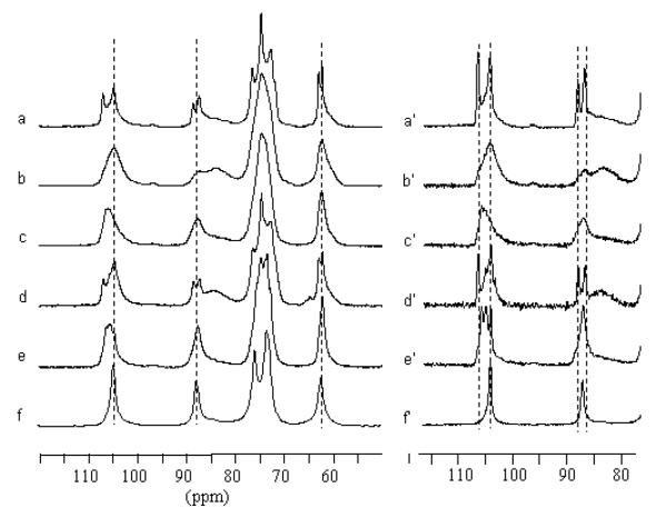
Samples were inserted individually into tightly sealed 4-mm BL type ZrO2 rotors. 13C CP/MAS NMR spectra were recorded with a Bruker Avance spectrometer equipped with a 4-mm BL type probe and operated at 100 MHz. The spectra were acquired at room temperature with a 100 kHz proton dipolar decoupling field, matched cross-polarization (CP) fields of 80 kHz, a proton 90° pulse of 2.5 μs and magic angle spinning (MAS) at a spinning speed of 12 kHz. The cross-polarization transfer was achieved using a ramped amplitude sequence (RAMP-CP) for an optimized total time of 2ms. The sweep width was of 50 000 Hz to avoid baseline distortion with 2 994 TD points, and the Fourier transformation was achieved without apodization over 8k points. The repetition time was 4 s and the average number of 20 000 scans was acquired for each spectrum. The 13C chemical shifts were determined relative to the carbon chemical shifts of the carbonyl signal of glycine at 176.03 ppm. Figure 1 shows the 13C CP/MAS spectra and resolution enhanced spectra recorded from cellulose II (mercerized ramie and Fortisan) before and after ammonia treatment at different temperatures. For comparison, a spectrum recorded from cellulose IIII is also shown. When clearly identified, the chemical shifts are reported in Table 1.
Figure 1.
13C CP/MAS NMR spectra recorded from a) Fortisan, b) Fortisan after ammonia treatment for 1h at 140°C, c) Fortisan after ammonia treatment for 1h at 160°C, d) mercerized ramie, e) mercerized ramie after ammonia treatment for 1h at 180°C, f) cellulose IIII produced by ammonia treatment of cellulose extracted from Cladophora,28,29 a′-e′) same as a-e) with resolution enhancement.
Table 1.
13C chemical shifts of the cellulose II and ammonia treated samples.
| Chemical shifts (ppm) | |||
|---|---|---|---|
| Sample | C1 | C4 | C6 |
| Cellulose II* | 107.0 ; 104.7 | 88.6 ; 87.4 84.3** |
62.9 ; 62.2 |
| Fortisan, 1h at 140°C | 104.9 | 87.4 ; 84.2** | 62.2 |
| Fortisan, 1h at 160°C | 106.1 | 87.7 ; ≈83.0** | |
| Mercerized Ramie, 1h at 180°C | 106.4 ; 105.7 ; 104.8 |
87.7 | 62.2 |
| Cell IIIII*** | 106.5 ; 105.7 ; 106.2** |
88.5 ; 87.3 ; 85.2** |
62.5 ; 62.1 ; 61.5** |
| Cell IIII | 104.8 | 87.8 | 62.3 |
Both Fortisan and mercerized ramie samples gave essentially the same chemical shifts
Broad amorphous contribution
Values taken from deconvolution data
Preliminary X-ray Data Collection
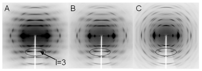
Beam line BL38B1 at SPring-8, Hyogo, Japan, (λ=1.0Å) together with a flat IP (R- AXIS V, Rigaku) were used to collect preliminary X-ray diffraction patterns from cellulose IIIII samples prepared from bundles of Fortisan and mercerized ramie fibers treated with ammonia at 180°C, as well as from a cellulose IIII sample for purposes of comparison, figure 2. The distributions of relative intensity in the cellulose IIIII diffraction patterns (figure 2a and 2b) are essentially the same. Although the distribution for cellulose IIII is similar (figure 2c), there are some marked differences. In particular, in the near meridian region on the third (l=3) layer line (enclosed in figure 2) there would appear to be a strong reflection for cellulose IIIII (indicated by an arrow) which is absent for cellulose IIII.
Figure 2.
Preliminary X-ray diffraction patterns collected from A) cellulose IIIII prepared from Fortisan, B) cellulose IIIII prepared from mercerized ramie, and C) cellulose IIII.
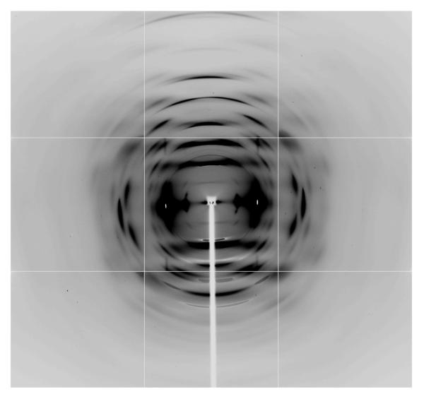
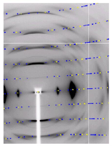
For the purposes of detailed structure determination, more extensive synchrotron X-ray data were collected at the NE-CAT beam line at the Advanced Photon Source (λ=0.9184Å; beam size of 300μm beam size, Quantum 315 detector) from the Fortisan cellulose IIIII sample, figure 3. This sample consisted of a number of individual fibers oriented in the same direction in a bundle about 1mm thick. Bragg reflections in this synchrotron X-ray diffraction pattern are sharper and extended to higher resolution, because of improved beam divergence. However, there is still a large amount of continuous diffuse scattering present on layer lines that indicates the presence of disorder. The strategies for collecting and processing NE-CAT X-ray diffraction data have been previously described in detail.49 Bragg reflections were indexed using a monoclinic unit cell that was almost orthorhombic with a=4.45Å, b=14.64Å, c=10.36Å, γ=90.05°, and with space group P21, figure 4. Data were processed using software from the BBSRC funded CCP13 project, Daresbury, UK. The relevant crystal data and a summary of intensity data collection and structure refinement are given in Table 2.
Figure 3.
A synchrotron X-ray diffraction pattern collected from cellulose IIIII prepared from Fortisan.
Figure 4.
A detail of the synchrotron X-ray diffraction pattern collected from cellulose IIIII prepared from Fortisan. Predicted reflection positions generated using a two-chain unit cell with a=4.45Å b=14.64Å c=10.36Å γ=90.05° and with space group P21 are shown in blue and yellow. The yellow positions represent a subset of these reflections that correspond to a reduced one-chain unit cell with a=4.45Å, b=7.64Å, c=10.36Å, γ=106.96°, and again with space group P21.
Table 2.
The experimental details of X-ray crystallographic data collection and the statistics of structure refinement.
| Crystal Data | |
| Chemical Formula | C12H20O10 |
| Cell setting, space group | monoclinic, P21 |
| a(Å) | 4.450(4) |
| b(Å) | 7.640(8) |
| c(Å) | 10.360(10) |
| α(°) | 90 |
| β(°) | 90 |
| γ(°) | 106.96(5) |
| V(Å3) | 336.9(5) |
| Radiation type | synchrotron X-ray |
| λ(Å) | 0.9184 |
| Data collection | |
| Diffractometer | NE-CAT |
| Independent reflections | 127 |
| θmax(°) | 18.2 |
| range of h | −4 −> 4 |
| range of k | −7 −> 7 |
| range of l | −9 −> 9 |
| Refinement | |
| R | 0.1582 |
| ωR(F2) | 0.4210 |
| Δρmax | 0.26 |
| Δρmin | −0.25 |
| ρrms | 0.07 |
X-ray Diffraction Scanning Microprobe Measurements.
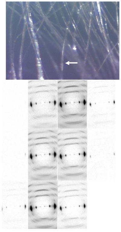
In order to search for a more crystalline region of the fiber sample that produced less diffuse scattering, and therefore had less disorder, synchrotron X-ray data were collected at the BioCAT beam line at the Advanced Photon Source in scanning microprobe geometry (λ=1.03Å beam size of 5μm) from individual fibers from the Fortisan cellulose IIIII sample bundle. A number of individual fibers were selected from a bundle, and then the beam was stepped across those fibers in 5μm steps. An example of one scan is shown in figure 5. We were unable to find a more crystalline region within any individual fiber and the diffraction patterns were consistently characterized by a mixture of diffuse and Bragg diffraction as we stepped across those fibers.
Figure 5.
Upper image: a fiber of around 40 μm in diameter is selected for scanning microprobe measurements. Lower image: A series of fiber diffraction patterns collected as a microprobe X-ray beam (5μm in diameter) is stepped across the individual fiber of cellulose IIIII, visualized in the upper image, with a step size of 5μm. The series proceeds from top to bottom and left to right.
Structure Refinement with a Large Two-Chain Unit Cell
X-ray structure refinement was carried out using previously described strategies for applying SHELX-9750 to fiber diffraction data.37 Atomic starting positions were taken from the chain conformation in the crystal structure of cellulose IIII 30, 31, which is similar to the average chain conformation in the crystal structure of cellulose II 36, 37. Initial refinements were carried out with two antiparallel two-fold helical chains positioned in the unit cell, one at the origin the other at the center resulting in values of 0.359 and 0.702 for R and Rω with 134 parameters and 172 restraints. A global thermal factor was used because there were not enough data and the data did not extend to sufficient resolution to refine individual displacement parameters.
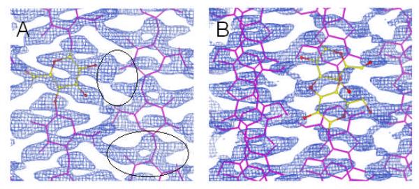
The corresponding 2Fo-Fc σA map contained density that indicated that the structure was incomplete, as shown in the circled regions of figure 6a. It was found that most of the density could be accounted for if the antiparallel “up” and “down” chains at the cell origin and center were superimposed onto each other at each chain position, figure 6b.51 Such an effect could result from the presence of twinning. Although, conventional merohedral twinning is not possible with a monoclinic unit cell, when γ is close to 90° as in this case, pseudo-merohedral twinning can occur. Testing for twinning with fiber diffraction data is complicated by the fact that each observed diffraction intensity is a composite of symmetry related and accidentally overlapping contributions. However, by trying various likely twinning laws with subsets of the data we were unable to significantly improve the refined structure. Another possible reason for the apparent superposition of “up” and “down” chains in figure 6b is the presence of statistical disorder. In such a disordered structure, the size of the unit cell is halved. In order to investigate the possibility of a smaller statistically averaged unit cell we reanalyzed the diffraction data.
Figure 6.
2Fo-Fc σA maps calculated from A) a two-chain P21 unit cell and B) the same unit cell but with the “up” and “down” chains superimposed. The circled regions in A) contain density that cannot be accounted for in the two-chain unit cell.
Reindexing the X-ray Diffraction Data using a Small One-Chain Unit Cell
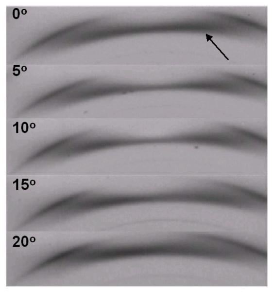
With the exception of the near meridian reflection on l=3 (013), all of the Bragg reflections can be indexed with a reduced unit cell with a=4.45Å b=7.64Å c=10.36Å γ=106.96° and with space group P21, exactly half the volume of the original large unit cell, figure 4. This unit cell is very similar to that of cellulose IIII. In order to investigate the nature of the putative (013) reflection for the large unit cell, we collected a fiber tilt series, corresponding to recording diffraction patterns as the meridian region of l=3 was taken through the Ewald sphere in 5° steps. The series, details of which are shown in figure 7, clearly shows that the strong intensity, indicated by an arrow, corresponds to continuous scattering confined to the layer-line and not a true Bragg reflection, thus confirming the choice of a reduced unit cell. Strong continuous scattering confined to layer-lines can also be observed in other regions of the diffraction pattern and would appear to be characteristic of our cellulose IIIII samples.
Figure 7.
Details of a fiber tilt series for cellulose IIIII prepared from Fortisan, recorded as the meridian region of l=3 was stepped through the Ewald sphere in increments of 5°. The putative (013) reflection, indicated by an arrow, is in fact not a true Bragg reflection but rather strong diffuse scattering confined to the merdional region of l=3.
Structure Refinement with a Small One-Chain Unit Cell
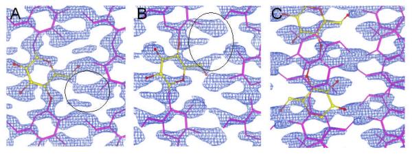
The smaller unit cell can accommodate only one chain. Refinements were carried with either a single “up” (R=0.249, Rω=0.552) or “down” (R=0.249 Rω=0.553) chain in the unit cell, with a total of 35 parameters and 42 restraints. The values of the R factors are similar between the “up” and “down” structures because they are almost mirror images of a quasi-orthorhombic unit cell. However, as in the refinements with the larger unit cell, the corresponding 2Fo-Fc σA maps contained density, circled in figures 8a and 8b, that indicates that the structure is incomplete. A refinement was then carried out with the unit cell equally occupied by two partial “up” and “down” chains. This refinement involved 68 parameters and 84 restraints and resulted in values of 0.158 and 0.421 for R and Rw, respectively. The corresponding 2Fo-Fc σA map contained no unaccounted for density, figure 8c, and would appear to indicate that this is the correct structure. The improvement in the fit to the electron density is reflected by a reduction in the rms deviation from the mean in the Fo-Fc maps from 0.21eÅ−3 and 0.16 eÅ−3 in the “up” and “down” single chain refinements to 0.07 eÅ−3 in the averaged “up” and “down” chain refinement.
Figure 8.
2Fo-Fc σA maps calculated from a one chain P21 unit cell with the chain in the A) “up” orientation, B) “down” orientation, and C) with chains randomly “up” and “down” with the same unit cell.
Results and discussion
The 13C CP/MAS NMR spectra recorded from mercerized ramie and Fortisan samples before ammonia treatment contain similar spectral features, typical for cellulose II, figures 1a and 1d. 52 In particular the clear splitting of the C1, C4 and C6 resonance lines reflects the fact that there are two distinct glucose residues in the asymmetric unit, corresponding to crystallographically independent antiparallel chains. The spectrum recorded from mercerized ramie contains a broad feature at about 85ppm due to the contribution from disordered chains to the C4 resonance line. This feature is also present in the spectrum recorded from Fortisan but at a lower intensity, indicating that the Fortisan sample is more crystalline.
The spectrum recorded from the Fortisan sample after treatment with ammonia at 140°C (figure 1b) does not show any significant shift in the positions of the resonance lines, but rather a broadening of the original lines corresponding to cellulose II so that they are no longer distinguishable as doublets. In addition, the broad signal at around 85ppm has become much stronger, indicating an increase in the amount of disordered chains. Treatment with ammonia at 140°C would therefore appear to cause a harsh decrystallization of cellulose II, but no transformation to another crystal phase.
On the other hand, the spectrum recorded from the Fortisan sample after treatment with ammonia at 160°C (figure 1c) displayed drastically different features from those in figures 1a and 1b. First, the position of the C1 resonance line in figure 1c is at a significantly higher value than in figures 1a and 1b. The mean position of this resonance line is also different from its position in cellulose IIII (figure 1f). Secondly, the intensity of the broad spectral feature at 85ppm does not differ greatly from its intensity in figure 1a, indicating that the sample is still relatively crystalline. Taken together, these observations would appear to indicate that treatment with ammonia at 160°C causes a transformation to another crystal phase, namely cellulose IIIII.
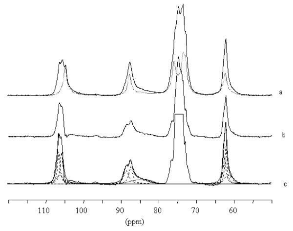
Unfortunately the broad features of the spectrum in figure 1c did not allow a clear interpretation of the resonance lines. However, a sample prepared from mercerized ramie by ammonia treatment at 180°C provided more detailed spectral features (figure 1e). In particular, the C1 resonance line can be seen to correspond to three distinct peaks. The resonance enhanced spectra of figures 1a-1f, shown in figures 1a′-1f′, show that the components of the C1 resonance line triplet do not correspond to any peaks in the spectrum recorded from cellulose II i.e. there is no residual cellulose II in the treated sample. However, there are features in figure 1e′ which corresponding to those seen in the spectrum recorded from cellulose IIII. In particular, the smallest of the three peaks for the C1 resonance triplet in figure 1e′ corresponds to the position of the C1 resonance line in figure 1f′. The spectrum in figure 1e′ can therefore be considered as a mixtures of two spectra, one which is similar to the spectrum recorded from cellulose IIII and another which contains resonance lines that have not been observed before.
In order to investigate this further, we subtracted the weighted cellulose IIII spectrum shown in figure 1f′ from the spectrum shown figure 1e′. This simple whole spectral difference analysis has an advantage over classical deconvolution methods in that it avoids assumptions about the position of peaks, especially when, as in the case of C4 and C6, they are not clearly identified. If we designate the components of the C1 triplet in figure 1e′ C1′, C1″ and C1‴, from low to high chemical shift respectively, then the C1′ signal can be identified with cellulose IIII. The cellulose IIII spectrum in figure 1f′ was weighted to the C1′ contribution in figure 1e′, as shown in figure 9a, and then subtracted from figure 1e′ to produce the subspectrum show in figure 9b. This subspectrum can be thought of as representative of a new structure that displays a clear C1″ and C1‴ doublet, as shown in figure 9c. Additional spectral features arise from this data treatment; the C4 contribution is also represented as a clear doublet. A tentative deconvolution of the C1, C4 and C6 contributions (including an amorphous contribution) indicates that the subspectrum can be decomposed into a series of doublets of approximately equal area, as in the case of cellulose II.
Figure 9.
13C CP/MAS spectra recorded from a) mercerized ramie treated with ammonia 1h at 180°C (solid line) and cellulose IIII (dashed line), b) spectrum obtained after subtraction of the cellulose IIII contribution from a), and c) tentative deconvolution of the preceding spectrum with crystalline (dotted lines) and amorphous (dashed lines) contributions.
These observations from our 13C CP/MAS NMR studies suggest that cellulose IIIII can be considered as a mixture of two components, one in which the conformation of the cellulose chains is the same as in cellulose IIII and another in which there are two distinct and crystallographically independent glucose residues with conformations that are different from those observed in other cellulose allomorphs.
The results from our crystallographic studies are consistent with this interpretation of the 13C CP/MAS NMR. Cellulose IIIII X-ray diffraction patterns collected from ammonia treated regenerated and mercerized cellulose II samples are essentially the same, indicating that they correspond to the same crystal phase. The lattice parameters of the statistically disordered unit cell for cellulose IIIII are similar to those for cellulose IIII. In this unit cell there is random statistical disorder between the placement of an “up” or “down” chain at each lattice point where the “up” molecule is placed at a height of 0 and the down molecule at a height of 0.28c (where the heights refer to the O4 atom positions of the “up” chain). Arnott 53 has shown that this type of statistical disorder results in Bragg diffraction from an “average” or “statistical” crystal and continuous intensity resulting from the difference between the “average” structure and the actual structure at each position. Statistical disorder therefore not only provides the best quantitative agreement with the Bragg reflection data but also a qualitative explanation of the regions of strong continuous layer line intensity that, as noted earlier, are characteristic of diffraction from cellulose IIIII. The X-ray diffraction scanning microprobe experiments indicate that this type of statistical disorder is present throughout the sample; on the scale of a few microns, no regions within the individual fibers were found in which a larger two-chain unit cell was dominant.
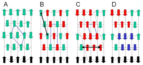
One way that this type of statistical disorder could arise is represented in figure 10. By slipping every alternate sheet containing antiparallel hydrogen bonded chains with respect to its neighboring sheets, along the direction of the long diagonal of the unit cell of cellulose II (figure 10a), so that the corner chain moves to the position of the center chain and vice-versa we obtain the large two-chain unit cell that we originally used to index cellulose IIIII (figure 10b). However, if not all of these sheets slip then there will be microdomains of the large unit cell generated, that are displaced with respect to each other; the up chain of one domain will be at an equivalent lattice point to the down chain in a neighboring domain. If there is further slippage along the direction indicated by the double arrow in figure 10c, then in additional, microdomains of cellulose IIII will be generated (blue regions in figure 10d). Diffraction will be from the averaged (statistically disordered) reduced one-chain unit cell as long as each Bragg reflection originates in a region of the sample that contains a number of these aggregated microdomains. The individual domains must therefore be relatively small, possibly only containing a few chains, hence our reference to them as microdomains.
Figure 10.
A) A schematic representation of the packing of cellulose chains in cellulose II. “up” and “down” chains are represented by upwards and downwards pointing green arrows. The unit cell of cellulose II is represented in blue. An hydrophobic stack of chains is indicated by black arrows. B) Alternate hydrogen bonded sheets of chains, represented by red arrows, have been slipped along the long axis of the cellulose II unit cell, in the direction indicated by the arrow, so as to generate the large unit cell originally used to index cellulose IIIII. C) A possible microdomain structure for cellulose IIIII that would account for the reduced, statistical unit cell, generated be incomplete slippage throughout the fiber along the direction indicated by black double arrow in B). D) Further slippage in the direction indicated by the black double arrow in C) generates an aggregate of microdomains of the large unit cell shown in B) and cellulose IIII.
There are other possible slippage disorders and chain migrations that could also account for the reduced unit cell of cellulose IIIII, and figure 10 represents just one possibility. Pseudo-merohedral twinning, however, seems unlikely. This type of twinning would generate the superposition of two sets of diffraction data from the large two-chain unit cell shown in figure 10b in two different orientations. However, we observe sharp Bragg reflections only from the smaller statistically averaged one chain unit cell.
From the statistically disordered crystallographic structure alone, it is not possible to resolve the detailed individual crystal structures of the different microdomains in cellulose IIIII. However, the results from the 13C NMR spectral studies provide a key. The cellulose IIII type microdomains in figure 10d can be clearly associated with cellulose IIII type spectral features recorded from cellulose IIIII and the detailed crystal structure of cellulose IIII has previously been reported.31 The microdomains of the larger two-chain unit cell shown in figure 10b can be associated with the subspectrum shown in figure 9b, and the following tentative insights can be made about the possible crystal structure of these microdomains.
The relative stagger of “up” and “down” chains along the c axis direction is 0.28c (2.93Å) where as in cellulose II it is only 0.23c (2.38Å). In addition to a rearrangement of chains in the direction perpendicular to the c axis there is therefore also a significant change in chain arrangement parallel to the c axis. This increase in chain stagger away from c/4 in cellulose II and towards c/3 in cellulose IIIII can be used to explain why the meridian region of diffraction is stronger on l=3 and weaker on l=4 in cellulose IIIII compared to cellulose II. A mixture of separate domains of cellulose II and cellulose IIII would not explain the observed relative stagger of “up” and “down” chains in the c axis direction and there is also no evidence for residual cellulose II in the 13C NMR spectra recorded from cellulose IIIII.
Packing the “up” and “down” chains in various arrangements that preserve the 0.28c stagger and the lateral organization of the chains results in steric clashes. However we note that the least amount of steric hindrance is obtained with the arrangement represented in figure 10b, and corresponding to the large two-chain unit cell. In this arrangement the O6 atom of the hydroxymethyl group of an “up” molecule could hydrogen bond with the O6 atoms of two neighboring “down” molecules and the O2 atom of an “up” molecule could hydrogen bond with the O2 atoms of two neighboring “down” molecules. The hydrogen bonding arrangement within sheets of alternating “up” and “down” molecules is preserved as in cellulose II. However, because neighboring sheets are slipped with respect to each other, the intersheet hydrogen bonding is very different, consisting of zig-zag networks of all O6-H…O6 hydrogen bonds or all O2-H…O2 hydrogen bonds.
The two zig-zag networks of hydrogen bonds would hold together stacks of hydrophobically packed chains, represented in black in figure 10b. As has been previously noted, these stacks consist of alternating “up” and “down” chains in cellulose II and parallel chains in cellulose IIII. Because of statistical disorder in cellulose IIIII, the stacks would consist of regions of parallel and antiparallel chains, and thus have features in common with both cellulose II and cellulose IIII.
Selected conformational parameters of the chain conformations refined for the averaged unit cell of cellulose IIIII are represented in table 4 and compared with those of the other cellulose allomorphs. Because of the effect of disorder we do not expect these to be accurate representations of the two crystallographically independent chains in the microdomains of the large two-chain unit cell. However, we note that the conformations of both the “up” and “down” chains are similar to those found in cellulose II. In particular, the hydroxymethyl groups of both chains adopt the gt conformation. These observations are consistent with interpretation of the subspectrum in figure 9c as consisting of a series of doublets for C1, C4 and C6.
Table 4.
Selected conformational parameters of cellulose IIIII compared with those of the other cellulose allomorphs. The conformation of the hydroxymethyl group is defined by two letters, the first referring to the torsion angle χ (O5-C5-C6-O6) and the second to the torsion angle χ′ (C4-C5-C6-O6). Thus the ideal tg and gt conformations would be respectively be defined as sets of two angles (180°, 60°) and (60°, 180°). The glycosidic bond angle, τ is defined by (C1-O4-C4). The glycosidic torsion angle Φ and Ψ, which describe the relative orientation of adjacent glucosyl residues in the same chain are defined by (O5-C1-O1-C4) and (C1-O1-C4-C3), respectively. For cellulose Iα “up” and “down” refer to the relative heights of crystallographically independent and adjacent glucosyl residues in the unit cell.
| Φ | Ψ | τ | χ | χ′ | θ | |
|---|---|---|---|---|---|---|
| Cellulose IIIII down | −87 | 85 | 118 | 84 | −157 | 5.4 |
| Cellulose IIIII up | −91 | 91 | 117 | 69 | −172 | 3.4 |
| Cellulose IIII | −92 | 93 | 116 | 44 | 163 | 10.5 |
| Cellulose II origin | −97 | 95 | 116 | 72 | −165 | 5.0 |
| Cellulose II center | −94 | 87 | 115 | 58 | −175 | 10.2 |
| Cellulose Iα up | −99 | 95 | 116 | 166 | −74 | 6.9 |
| Cellulose Iα down | −98 | 99 | 116 | 167 | −75 | 9.4 |
| Cellulose Iβ origin | −98 | 90 | 115 | 170 | −70 | 10.2 |
| Cellulose Iβ center | −89 | 94 | 116 | 158 | −83 | 6.7 |
During the conversion of cellulose II to cellulose IIIII, the complex of ammonia and cellulose had to be held at 160-180°C, the maximum temperature that could be used without introducing a significant amount of cellulose IVII. This conversion temperature is much higher than the temperature required for conversion of cellulose I to cellulose IIII (~140°C). In cellulose I, sheets of hydrogen bonding chains are stacked on top of each other through hydrophobic interactions. During conversion to cellulose IIII, these sheets can relatively easily slip with respect to each other. However, in the case of cellulose II the sheets of hydrogen-bonded chains are stacked on top of each other through hydrogen bond interactions. During conversion to cellulose IIIII these hydrogen bonds must be broken, and it may also be that there is a more extensive chain migration, both which may contribute to the higher temperature required for conversion.
Conclusion
The crystallographic and spectroscopic studies reported here indicate that cellulose IIIII is a statistically disordered phase of cellulose. It may be that with further exploration and refinement of amine treatments of cellulose II, or subsequent treatments of cellulose IIIII, a more ordered phase will be found. It may also be possible that statistical disorder is a characterizing property of cellulose IIIII. We have proposed a possible explanation for the origin of this disorder that would appear to be consistent with both the crystallographic and spectroscopic results. However, we acknowledge that there may be other possible explanations.
Supplementary Material
Table 3.
Fractional Atomic Coordinates. The value of the mean square atomic displacement parameter is 0.05.
| Atom | x | y | z |
|---|---|---|---|
| “Down” molecule | |||
| O2 | 0.68488 | −0.37630 | 0.40489 |
| O3 | 0.87119 | −0.28100 | 0.66392 |
| O4 | 1.02248 | −0.11465 | 0.22064 |
| O5 | 1.15127 | 0.10212 | 0.37810 |
| O6 | 1.21602 | 0.49674 | 0.44536 |
| C1 | 0.92234 | −0.06377 | 0.33869 |
| C2 | 0.91582 | −0.21013 | 0.43949 |
| C3 | 0.84574 | −0.14684 | 0.57200 |
| C4 | 0.93112 | −0.04051 | 0.10489 |
| C5 | 1.06807 | 0.17557 | 0.49643 |
| C6 | 1.30366 | 0.35964 | 0.51557 |
| H1 | 0.71466 | −0.04491 | 0.33011 |
| H2 | 1.12218 | −0.23189 | 0.44173 |
| H3 | 0.62980 | −0.13903 | 0.57275 |
| H4 | 0.71811 | −0.03018 | 0.11550 |
| H5 | 0.85745 | 0.19036 | 0.48815 |
| H6A | 1.31803 | 0.39029 | 0.60667 |
| H62B | 1.50878 | 0.35512 | 0.48691 |
| “Up” Molecule | |||
| O2 | 1.18281 | 1.38162 | 0.32614 |
| O3 | 1.20116 | 1.28786 | 0.06276 |
| O4 | 1.18130 | 1.09163 | 0.50024 |
| O5 | 1.01778 | 0.88426 | 0.33876 |
| O6 | 0.64790 | 0.51577 | 0.28795 |
| C1 | 1.01893 | 1.06205 | 0.38261 |
| C2 | 1.18683 | 1.20394 | 0.28520 |
| C3 | 1.02633 | 1.15882 | 0.15457 |
| C4 | 0.99814 | 1.03693 | 0.61541 |
| C5 | 0.84177 | 0.83024 | 0.22131 |
| C6 | 0.83586 | 0.63567 | 0.19505 |
| H1 | 0.80317 | 1.06692 | 0.39496 |
| H2 | 1.40526 | 1.20182 | 0.27763 |
| H3 | 0.81407 | 1.17173 | 0.16076 |
| H4 | 0.78655 | 1.04766 | 0.60109 |
| H5 | 0.62667 | 0.83634 | 0.23349 |
| H6A | 0.75191 | 0.60042 | 0.10939 |
| H6B | 1.04826 | 0.62590 | 0.19779 |
Acknowledgements
We thank beam line BL38B1 at the SPring-8, Japan, and beam lines NECAT and BIOCAT at the Advanced Photon Source, for use of facilities. We also thank Raul Barrea, Joseph Orgel, and Narayanasami Sukumar for help with data collection on BIOCAT and NECAT. MW was supported by a Grant-in-Aid for Scientific Research (18780131). This study was partly funded by the French Agence Nationale de la Recherche. PL was supported in part by the Office of Biological and Environmental Research of the Department of Energy, a grant from the National Institute of Medical Sciences of the National Institutes of Health (1R01GM071939-01), and a Laboratory Directed Research and Development grant from Los Alamos National Laboratory (20080001DR).
References
- 1.Clark GL, Parker EA. J. Phys. Chem. 1937;41:777–786. [Google Scholar]
- 2.Davis WE, Barry AJ, Peterson FC, King AJ. J. Am. Chem. Soc. 1943;65:1294–1299. [Google Scholar]
- 3.Klemm D, Philipp B, Heinze U, Wagenknecht W. Comprehensive Cellulose Chemistry. I. Wiley-VCH; New York: 1998. pp. 152–154. [Google Scholar]
- 4.Klenkova NI. Zh. Prikl. Khim. 1967;40:2191–2208. [Google Scholar]
- 5.da Silva Perez D, Montanari S, Vignon MR. Biomacromolecules. 2003;4:1417–1425. doi: 10.1021/bm034144s. [DOI] [PubMed] [Google Scholar]
- 6.Detroy RW, Lindenfelser LA, Sommer S, Orton WL. Biotechnology and Bioengineering. 1981;23:1527–1536. [Google Scholar]
- 7.Umikalsom MS, Ariff AB, Zulkifli HS, Tong CC, Hassan MA, Karim MIA. Bioresource Technology. 1997;62:1–9. [Google Scholar]
- 8.Lokhande HT. J. Appl. Polym. Sci. 1976;20:2313. [Google Scholar]
- 9.Yanai Y, Shimizu Y. Sen'i Gakkaishi. 2006;62:100–105. [Google Scholar]
- 10.Pandey SN, Nair P. Text. Res. J. 1975;45(9):648–653. [Google Scholar]
- 11.Lee MS, Lee M, Tokuyama T, Wakida T, Inoue G, Ishida S. J. App. Polym. Science. 2006;101:3487–3492. [Google Scholar]
- 12.Lewin M, Rau RO, Sello SB. Text. Res. J. 1974;44:680–686. [Google Scholar]
- 13.Teymouri F, Laureano-Perez L, Alizadeh H, Dale BE. Biosour. Technol. 2005;96:2014. doi: 10.1016/j.biortech.2005.01.016. [DOI] [PubMed] [Google Scholar]
- 14.Jahan MS, Farouqui FI. Holzforschung. 2000;54:625–630. [Google Scholar]
- 15.Zargarian K, Aravamuthan R, April GC. Chem Eng Technol. 1988;11:195–199. [Google Scholar]
- 16.Herrick FW. J. Appl. Polym. Sci.: Appl. Poly. Symp. 1983;37:993–1023. [Google Scholar]
- 17.Bonner WS. US Patent 1,173,336 1916
- 18.Schleicher H, Daniels C, Philipp B. J. Polym. Sci. Polym Symp. 1974;47:251–260. [Google Scholar]
- 19.Schuerch C. US Patent, 3,282,313 1964
- 20.Lindberg KJ. US Patent 3,406,006 Stranger-Johannessen. 1965
- 21.Chanzy H, Henrissat B. Carbohydrate Research. 1987;160:1–11. [Google Scholar]
- 22.Chanzy H, Henrissat B, Voung R, Revol JF. Holfzforschung. 1986;40(supp):25–30. [Google Scholar]
- 23.Sugiyama J, Vuong R, Chanzy H. Macromolecules. 1991;24:4168–4175. [Google Scholar]
- 24.Sugiyama J, Okano T, Yamamoto H, Horii FJ. Macromolecules. 1990;23:3196–3198. [Google Scholar]
- 25.Nishiyama Y, Sugiyama J, Chanzy H, Langan P. J. Am. Chem. Soc. 2003;125:14300–14306. doi: 10.1021/ja037055w. [DOI] [PubMed] [Google Scholar]
- 26.Nishiyama Y, Langan P, Chanzy H. J. Am. Chem. Soc. 2002;124:9074–9082. doi: 10.1021/ja0257319. [DOI] [PubMed] [Google Scholar]
- 27.Wada M, Nishiyama Y, Langan P. Macromolecules. 2006;39:2947–2952. [Google Scholar]
- 28.Wada M, Kwon GJ, Nishiyama Y. Biomacromolecules. 2008;9:2898–2904. doi: 10.1021/bm8006709. [DOI] [PubMed] [Google Scholar]
- 29.Wada M, Heux L, Nishiyama Y, Langan P. Biomacromolecules. 2008 doi: 10.1021/bm8010227. submitted to. [DOI] [PMC free article] [PubMed] [Google Scholar]
- 30.Wada M, Heux L, Isogai A, Nishiyama Y, Chanzy H, Sugiyama J. Macromolecules. 2001;34:1237–1243. [Google Scholar]
- 31.Wada M, Chanzy H, Nishiyama Y, Langan P. Macromolecules. 2004;23:8548–8555. [Google Scholar]
- 32.Igarashi K, Wada M, Samejima M. FEBS Journal. 2007;274:1785–1792. doi: 10.1111/j.1742-4658.2007.05727.x. [DOI] [PubMed] [Google Scholar]
- 33.Wada M. Macromolecules. 2001;34:3271–3275. [Google Scholar]
- 34.Horii F, Yamamoto H, Kitamaru R, Tanahashi M, Higuchi T. Macromolecules. 1987;20:2946–2949. [Google Scholar]
- 35.Yamamoto H, Horii F, Odani H. Macromolecules. 1989;22:4130–4132. [Google Scholar]
- 36.Langan P, Nishiyama Y, Chanzy H. J. Am. Chem. Soc. 1999;121:9940–9946. [Google Scholar]
- 37.Langan P, Nishiyama Y, Chanzy H. Biomacromolecules. 2001;2:410–416. doi: 10.1021/bm005612q. [DOI] [PubMed] [Google Scholar]
- 38.Amano Y, Nozaki K, Araki T, Shibasaki H, Kuga S, Kanda T. Cellulose. 2001;8:267–274. [Google Scholar]
- 39.Hess K, Trogus C. Ber. 1935;B68:1986–1988. [Google Scholar]
- 40.Hayashi J, Sueoka A, Ohkita J, Watanabe S. Polymer Letters Edition. 1975;13:23–27. [Google Scholar]
- 41.Chen Y, Stipanovic AJ, Winter WT, Wilson DB, Kim YJ. Cellulose. 2007;14:283–293. [Google Scholar]
- 42.Sueoka A, Hayashi J, Watanabe S. Nippon Kagaku Kaishi. 1973:594–602. [Google Scholar]
- 43.Marrinan HJ, Mann J. J. Polym. Sci. 1956;XXI:301–311. [Google Scholar]
- 44.Isogai A, Usuda M, Kato T, Uryu T, Atalla RH. Macromolecules. 1989;22:3168–3172. [Google Scholar]
- 45.Sarko A, Southwick J, Hayashi J. Macromolecules. 1976;9:857–863. [Google Scholar]
- 46.The conformation of the hydroxymethyl group is defined by two letters, the first referring to the torsion angle χ (O5-C5-C6-O6) and the second to the torsion angle χ′ (C4-C5-C6-O6). Thus the ideal tg and gt conformations would be respectively be defined as sets of two angles (180°, 60°) and (60°, 180°). The glycosidic bond angle, τ is defined by (C1-O4-C4). The glycosidic torsion angle Φ and ψ, which describe the relative orientation of adjacent glucosyl residues in the same chain are defined by (O5-C1-O1-C4) and (C1-O1-C4-C3), respectively.
- 47.Hori R, Wada M. Cellulose. 2006;13:281–290. [Google Scholar]
- 48.Yatsu LY, Calamari TA, Benerito RR. Text. Res. J. 1986;56:419–424. [Google Scholar]
- 49.Langan P, Sukumar N, Nishiyama Y, Chanzy H. Cellulose. 2005;12:551–562. [Google Scholar]
- 50.Sheldrick GM. SHELX-97, a program for the refinement of Single-Crystal Diffraction Data. University of Göttingen; Göttingen, Germany: 1997. [Google Scholar]
- 51.When the z coordinate of O5 is greater than that of C6, the chain is defined as “up”, otherwise as “down”.
- 52.Dudley RL, Fyfe CA, Stephenson PJ, Deslandes Y, Hamer GK, Marchessault RH. J. Am. Chem. Soc. 1983;105:2469–2472. [Google Scholar]
- 53.Arnott S. Fiber diffraction analysis of biopolymer molecules. Trans. Am. Cryst. Assoc. 1973;9:31–56. [Google Scholar]
Associated Data
This section collects any data citations, data availability statements, or supplementary materials included in this article.


