

Abstract
An integrated optoacoustic transducer combining etalon and black polydimethylsiloxane (PDMS) structures has been designed and developed. The device consists of an 11-μm-thick black PDMS film confined to a 2-mm-diameter circular region acting as an optoacoustic transmitter, surrounded by a 5.9-μm Fabry-Perot polymer etalon structure serving as an optoacoustic detector array. A pulsed laser is focused onto a 30-μm spot on the black PDMS film, defining the transmit element, while a CW laser probes a 20-μm spot on the etalon for ultrasound detection. Pulse-echo signals display center frequencies of above 30 MHz with bandwidths of at least 40 MHz. A theta-array is formed for 3-D ultrasound imaging by mechanically scanning the generation laser along a 1-D array and the detection laser around an annular array. Preliminary images with 3 metal wires as imaging targets are presented. Characterization of the device’s acoustical properties, as well as preliminary imaging results, suggest that all-optical ultrasound transducers are potential alternatives to piezoelectric techniques for high-frequency 2-D arrays enabling 3-D high-resolution ultrasound imaging.
I. Introduction
The frontiers of high-frequency ultrasound have been greatly expanded during the past decade, with various applications in dermatology [1]–[2], ophthalmology [3]–[4], intravascular imaging (IVUS) [5], and small animal imaging [6]. An integral part of any ultrasound imaging system is the transducer array, which generates and detects acoustic waves, and ultimately determines image resolution and quality. Currently, the unavailability of 2-D high-frequency piezoelectric transducer arrays limits further development of high-frequency ultrasound, especially in real-time 3-D high-resolution applications. State-of-the-art piezoelectric arrays include a 64-element 35-MHz 1-D array [7] and an 8-element 55-MHz annular array [8], whereas 2-D arrays have not been fabricated at high frequencies [9]–[10]. Major fabrication challenges include dicing piezoceramics to micron-scale elements and making electrical connections to each individual element. Recently, the capacitive micromachined ultrasound transducer (CMUT) has been developed as an alternative [11]. A 64-element 1-D linear array operating at 45 MHz [12] and 64-element forward-looking annular arrays [13]–[14] have been reported. However, even though a high-frequency fully sampled 2-D CMUT array is theoretically realizable, no such array has been implemented, and integration of front-end electronics still requires a technical breakthrough. Clearly, a new transduction technology is greatly needed for 2-D arrays operating at above 30 MHz.
An attractive alternative, optoacoustic transduction, typically replaces electronic signals with 2 laser beams as input/output vectors, one for ultrasound generation and the other for ultrasound detection. The most significant advantage over piezoelectricity is that the size and spacing of each transmit/receive array element is defined by the focal spot of a laser beam, which is easily reduced to several microns using conventional optics. Also, an array can be easily formed by splitting the primary laser beam and focusing the resultant secondary beams onto a configurable array of spots, which avoids transducer dicing and making electrical connections.
The most efficient optoacoustic transmitter utilizes either an 11-μm-thick black polydimethylsiloxane (PDMS) film [15]–[16], or a 4.5-μm gold nanostructure PDMS film [17]. In a typical configuration, a laser pulse is focused onto the film, and optical absorption rapidly heats a localized volume in which thermal expansion launches an acoustic wave into the overlying sample. The bandwidth of generated ultrasound can easily exceed 50 MHz with a 5-ns incident laser pulse, and the surface acoustic pressure often rises well beyond 100 MPa with sufficient input optical energy.
On the other hand, the most effective method for optoacoustic detection uses a thin polymer etalon [18]–[21], which consists of a polymer layer sandwiched between 2 reflecting mirrors. The strain associated with an ultrasound wave passing through the etalon modulates its thickness and therefore changes the reflected optical intensity of the probing CW laser beam. The acoustic pressure can be measured by recording the intensity change of the reflected signal. A 5.9-μm-thick etalon [22] possesses bandwidth of well over 50 MHz, noise equivalent pressure of 3.9 kPa for a 20-μm-diameter element, better than that of PVDF equivalents, and angular attenuation of barely 10 dB at 45 degrees for frequencies approaching 80 MHz.
In this paper, we propose an integrated all-optical theta-array system combing an 11-μm-thick black PDMS film and a 5.9-μm-thick etalon. The fabrication and configuration of the device will first be described, followed by ultrasound pulse-echo characterization. Preliminary images obtained using 3 metal wires as imaging targets will also be presented.
II. Fabrication and Structure
The first step is to fabricate a 5.9-μm SU-8 etalon with a 2-mm-diameter transparent window on top of a glass substrate. A 30-nm gold layer is first deposited as the first reflecting mirror using an electron beam evaporator, where a 2-mm-diameter tape is masked on glass to block the deposition of gold within the region. Then SU-8 photoresist (SU-8 2005, Microchem Corp., Newton, MA) is spin coated on top at 2100 rpm for 40 s after the tape is peeled off. The cured film is about 5.9 μm thick and forms the etalon’s polymer bulk layer. A 2-mm-diameter tape is masked on the same region again, and another 30-nm gold layer is deposited as the second reflecting mirror. A mixture of PDMS (Sylgard 184, Dow Corning, Midland, MI) and carbon black (Raven 14, Columbian Chemicals Inc., Marietta, GA) with mass ratio of 6:1 is then spin coated into an 11-μm black PDMS film on top. A side view of the device is shown in Fig. 1. The 2-mm transparent window in the middle of the etalon allows a pulsed laser beam to be focused onto the black PDMS film for ultrasound generation, while a CW laser beam is focused onto the remainder of the etalon for ultrasound detection.
Fig. 1.

Side view of the optoacoustic device’s structure. A 5.9-μm SU-8 etalon with a 2-mm-diameter window is fabricated on a glass substrate, followed by an 11-μm black PDMS film on top.
III. Acoustical Properties
The 11-μm-thick black PDMS film and the 5.9-μm-thick etalon have been previously characterized for optoacoustic transmission [16] and detection [22], respectively. However, the PDMS layer changes the acoustical properties of the etalon, as it attenuates ultrasound by about 1 dB/μm at about 60 MHz [16], and affects the frequency response of the etalon by changing the overall structure thickness. Therefore, the acoustic frequency response of the etalon needs to be reinvestigated.
The etalon’s optical resonance is first measured by recording the reflected optical intensity as the wavelength is scanned from 1480 nm to 1550 nm, as shown in Fig. 2(a). The resonance wavelength is 1513 nm with FWHM of 6.3 nm. Therefore, the wavelength of the probing beam is tuned to 1511.5 nm for maximum detection sensitivity. The frequency response of the etalon is characterized using a 50-MHz LiNbO3 piezoelectric transducer with a diameter of 2.5 mm and focal length of 4 mm (Resource Center for Medical Ultrasonic Transducer Technology, University of Southern California, CA). First, the pulse-echo signal reflected from a glass substrate is recorded by the piezoelectric transducer. Then the transducer is placed a focal length away above the etalon, and the signal from the piezoelectric transducer is recorded from the etalon. Water is used as the coupling medium here, as well as in all experiments throughout this paper. Both the etalon signal and the transducer pulse-echo signal are displayed in Fig. 2(b). The frequency response of the etalon is derived by dividing the spectrum of the etalon signal by the square root of the spectrum of the transducer pulse-echo signal. All 3 spectra are displayed in Fig. 2(c). Clearly, the 5.9-μm-thick etalon can detect ultrasound at 50 MHz and above even with an 11-μm black PDMS layer on top.
Fig. 2.

(a) Optical resonance of the 5.9-μm-thick SU-8 etalon with 11-μm-thick black PDMS on top; (b) the etalon signal and the transducer pulse-echo signal; (c) spectrum of the etalon signal, the square root of the spectrum of pulse-echo signal of the piezoelectric transducer, and the frequency response of the etalon.
An ultrasound pulse-echo experiment is performed using the setup shown in Fig. 3(a). The integrated optoacoustic transducer is mounted at the bottom of a water tank. The pulsed laser excitation source is a commercial pulsed fiber laser (MIRVISION, Keopsys Inc., Lannion, France), which produces a 5 ns pulse with energy of 200 nJ/pulse at wavelength of 1064 nm and repetition rate of 5 kHz. The beam is output through a multimode fiber with core size of 18 μm, followed by a collimator with focal length of 12 mm and a convex lens with focal length of 20 mm. The beam is then reflected from a dielectric mirror before being focused onto a roughly 30 μm spot on the black PDMS film. The dielectric mirror is designed to be highly reflective at wavelengths of 1000 nm to 1100 nm and highly transmittable at wavelengths of 1300 nm and higher. The generated ultrasound is reflected back from a glass reflector positioned parallel to the device surface and 1.7 mm away.
Fig. 3.

(a) Experimental setup of the pulse-echo experiment; a 5-ns pulsed laser is focused onto the black PDMS for ultrasound generation, and a CW laser pulse is focused onto the etalon for ultrasound detection; (b) top view of generation and detection element geometry. Here d is the center-to-center distance between the generation and detection elements.
The pulse-echo ultrasound signal is detected by a CW laser beam at 1511.5 nm with power of 4 mW. It travels through a polarizing beam splitter and a quarter-wave plate before being focused onto a 20 μm spot on the etalon through the dielectric mirror. The center-to-center distance between the generation and detection spots is denoted as d. Fig. 3(b) shows the top view of the geometry.
The pulse-echo signals for generation and detection elements separated by 1 mm (d = 1 mm), 0.6 mm (d = 0.6 mm), and 0.2 mm (d = 0.2 mm), averaged 1000 times, are shown in Fig. 4(a), (c), and (e) respectively. The spectrum for d = 1 mm is shown in Fig. 4(b), where the center frequency is 33 MHz and the −6 dB bandwidth is 41 MHz. The center frequency and bandwidth increase with shorter distance, as demonstrated in Figs. 4(d) and (f), where d is 0.6 mm and 0.2 mm, respectively. For instance, if d = 0.2 mm, the center frequency is 34 MHz whereas the −6 dB bandwidth is 51 MHz. This increase occurs primarily because the frequency response of the etalon is incident angle dependent and always displays attenuation at higher angles [22]–[23]. Therefore, shorter distance leads to a smaller incident angle for the echo ultrasound waves, which consequently produces broader bandwidth.
Fig. 4.

Pulse-echo signal averaged 1000 times when (a) d = 1 mm; (c) d = 0.6 mm; (e) d = 0.2 mm; Spectrum of the pulse-echo signal averaged 1000 times when (b) d = 1 mm; (d) d = 0.6 mm; (f) d = 0.2 mm.
IV. Ultrasound Imaging
In this device, generation and detection elements are spatially separate. The simplest array that separates transmit and receive elements is the Mills cross [24], which consists of a straight line of transmit elements and another straight line of receive elements in a perpendicular direction. However, this configuration is not feasible due to limitations in our device structure. The first-order approach utilizes a theta-array geometry, which contains a straight line of transmit elements and an annular-ring array [25]–[30] of detection elements surrounding the transmit elements. This configuration is the simplest 2-D array for a preliminary 3-D imaging test with our device structure.
An optoacoustic theta-array is illustrated in Fig. 5(a). The generation pulsed laser beam is scanned along a straight line to provide the optoacoustic transmission array, and the probe CW laser is scanned over an annulus to form the optoacoustic detection array. The setup is the same as in the pulse-echo experiment shown in Fig. 3(a), except both lasers are controlled by separate motors for scanning. In our imaging experiment, the transmission array consists of 8 elements with 200 μm center-to-center separation between adjacent elements, and the detection array contains 400 elements along a circle with 2.5 mm diameter (19.6 μm center-to-center separation between adjacent elements).
Fig. 5.

(a) Illustration of the optoacoustic theta-array configuration: the transmission array consists of 8 elements with 200 μm separation between adjacent elements, and the detection array contains 400 elements along a circle with 2.5 mm diameter; (b) wavefield of recorded pulse-echo signals from the annular detection array when the generation element is aligned to the center.
The center of the circular window is defined as the origin of the coordinate system. Because generation and detection beams are controlled by independent motor systems, it is important to first align the generation beam to the center of the annular detection array (origin of the coordinate system). After alignment, pulse-echo signals are recorded at all 400 detection elements, and the ultrasound wavefield is shown in Fig. 5(b). Clearly, the travel times from the generation spot to all detection spots are equal, verifying that the pulsed laser is indeed focused onto the center of the detection array.
As a preliminary test using the theta-array, 3 50-μm-diameter metal wires are used as imaging targets. The experimental configuration and the wire arrangement are shown in Fig. 6, where the wires are placed roughly 1.8 mm from the device surface. A synthetic aperture approach is followed for data acquisition. When the generation laser is focused onto each generation element spot, the probe laser is scanned through the annular detection array, and the ultrasound signal at each position, averaged 1000 times, is recorded. A full data set containing every combination of transmit and receive elements is obtained. The wavefield plot of the detected acoustic field along this annular array for one of the generation spots is shown in Fig. 7. Because there are 400 receiving elements evenly spread out on the annular detection array, the vertical axis is sampled every 0.9 degree. Clearly, the 3 wires are well represented by the 3 distinctive curves in this wavefield.
Fig. 6.
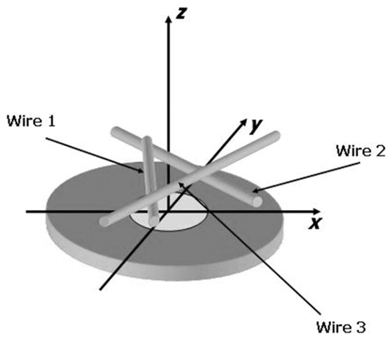
Geometry and experimental configuration used to image 3 metal wires.
Fig. 7.
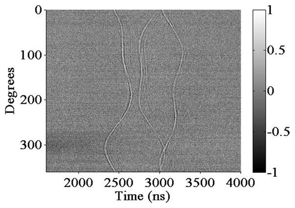
Wavefield plot of the detected acoustic field along the annular detection array for one of the generation spots.
Band-pass filtering from 25 to 75 MHz is applied to all signals to balance desired resolution and dynamic range. Conventional beamforming algorithms are then used for image reconstruction. The reconstructed image from the x–y plane at z = 1790 μm, which intersects the first wire, is shown in Fig. 8(a), while the reconstructed image from the x–y plane at z = 2020 μm, which intersects the joint of the second and third wires, is shown in Fig. 8(b). The display dynamic range of both figures is 10 dB. Correspondingly, expected images as determined by the geometry of the 3 wires are shown in Fig. 8(c) and (d), respectively. The reconstructed images capture the existence of the 3 wires, and the geometry of the imaging targets are depicted overall, confirming the optoacoustic theta-array’s potential for 3-D ultrasound imaging. Note that artifacts do exist, and there is a certain degree of distortion in the reconstructed images. Methods for improvements are discussed below.
Fig. 8.

Reconstructed image from the x–y plane at (a) z = 1790 μm; (b) z = 2020 μm, image dynamic range is 10 dB; expected image from the x–y plane at (c) z = 1790 μm; (d) z = 2020 μm.
V. Discussion and Summary
At present, image quality is mainly limited by the small number of optoacoustic transmission elements. Sufficiently high pulsed laser energy is not available for our experiments; thus, extensive signal averaging of 1000 times is required at each detection array element. The total time consumed at each generation element is a few hours, including mechanically scanning through the annular detection array, signal averaging, and data acquisition. Time constraints force us to use a maximum of 8 generation elements with separation of 200 μm, whereas significantly more generation elements with separation of less than 20 μm are of course highly desired to reduce artifacts and greatly improve image quality.
In our experiments, optical pulses with 200 nJ/pulse are delivered to a spot size of 30 μm for ultrasound generation, yielding an optical fluence of 0.03 J/cm2, whereas the thermal damage threshold has been measured to be 30 J/cm2 [16]. With substantial improvements in fiber selection and preparation, as well as system configuration in our current system, much higher input optical energy can be achieved. Alternatively, commercial pulsed lasers with energy much higher than that used in our setup are available, thus the SNR of ultrasound signals can be improved by at least 40 dB using an optical energy of 20 μJ/pulse. This would enable us to record single-shot signals at each array element, enabling a significantly larger number of generation elements.
Another main drawback of our current experimental system is the mechanical scan of lasers to form the generation and detection arrays. The detection CW laser beam is controlled by a 2-D motor system that scans the beam in the designated annular geometry. Meanwhile, the generation pulsed laser beam is controlled by a 1-D motor and is scanned along the x-axis as denoted in Fig. 5(a). Because the pulsed laser beam is reflected from a dielectric mirror, the actual transmit element spot largely depends on the exact position and angle of the dielectric mirror, especially when the spot is moved away from the center. If the dielectric mirror’s angle and position are not tuned to perfection, the transmit element spot will be off from the proposed position by an uncertain distance, and a significant amount of error during image reconstruction will be induced because the assumed round-trip delay between generation and detection elements is no longer accurate. We attribute various artifacts in the reconstructed images to this effect.
Simultaneous ultrasound detection from all array elements at each firing of an individual generation element would decrease imaging time significantly, making real-time imaging possible. A system with an optical end capable of parallel probing [31] has previously been built, in which an unfocused laser beam probes a large area on the etalon surface, and a photodetector is scanned to acquire signals from all channels. The most practical proposed solution utilizes a fiber bundle [32], which splits the primary laser beam into an array of separate laser beams that are then focused onto a programmable array geometry on the device surface. Immediate future work includes optimizing the optical setup involving fiber bundles, fabricating etalons with better thickness uniformity, and evaluating photodetector arrays.
The major drawback of this integrated optoacoustic device combining black PDMS films and etalon structures is that transmission elements and detection elements must be spatially separate. This means that fully-sampled 2-D arrays are not available with this device. An integrated single element capable of both ultrasound generation and detection can be fabricated using a gold nanostructure as optoacoustic transmitter [32]. The advantage of using black PDMS over a gold nanostructure, however, is that its thermal damage threshold is 6 times higher [16]–[17], enabling higher ultimate acoustic pressures.
In summary, we have fabricated and tested an integrated optoacoustic device for 3-D ultrasound imaging. The device consists of an 11-μm-thick black PDMS film confined to a 2-mm-diameter circular region acting as an optoacoustic transmitter, surrounded by a 5.9-μm-thick Fabry-Perot polymer etalon structure serving as an optoacoustic detector array. Pulse-echo signals display center frequencies above 30 MHz with bandwidths of at least 40 MHz with a 30-μm generation element and a 20-μm detection element. A theta-array is emulated by mechanically scanning the generation laser beam through 8 1-D elements with 200 μm center-to-center separation and the detection laser beam along an annular array of 400 elements each separated by 19.6 μm. The wavefield plot and reconstructed images are capable of capturing the 3 wires used as imaging targets. Acoustical characterization, together with preliminary imaging results, demonstrates the potential of optoacoustic transducers for 3-D ultrasound imaging.
Acknowledgments
This work is supported in part by NIH under grants EB003455, EB003449 and EB004933.
The authors would like to thank the Resource Center for Medical Ultrasonic Transducer Technology at the University of Southern California for supplying high-frequency transducers.
References
- 1.Turnbull DH, Starkoski BG, Harasiewicz KA, Semple JL, From L, Gupta AK, Sauder DN, Foster FS. A 40–100 MHz B-scan ultrasound backscatter microscope for skin imaging. Ultrasound Med Biol. 1995;21(1):79–88. doi: 10.1016/0301-5629(94)00083-2. [DOI] [PubMed] [Google Scholar]
- 2.Passman C, Ermert H. A 100 MHz ultrasound imaging system for dermatologic and ophthalmologic diagnostics. IEEE Trans Ultrason Ferroelectr Freq Control. 1996;43(4):545–552. [Google Scholar]
- 3.Foster FS, Pavlin CJ, Lockwood GR, Ryan LK, Harasiewicz KA, Berube L, Rauth AM. Principles and applications of ultrasonic backscatter microscopy. IEEE Trans Ultrason Ferroelectr Freq Control. 1993;40(5):608–616. doi: 10.1109/58.238115. [DOI] [PubMed] [Google Scholar]
- 4.Coleman DJ, Silverman RH, Chabi A, Rondeau MJ, Shung KK, Cannata J, Lincoff H. High-resolution ultrasonic imaging of the posterior segment. Ophthalmology. 2004;111(7):1344–1351. doi: 10.1016/j.ophtha.2003.10.029. [DOI] [PubMed] [Google Scholar]
- 5.White RA, Donayre CE, Kopchock GE, Walot I, Mehinger CM, Wilson EP, de Virgilio C. Vascular imaging before, during and after endovascular repair. World J Surg. 1996;20(6):622–629. doi: 10.1007/s002689900095. [DOI] [PubMed] [Google Scholar]
- 6.Foster FS, Zhang MY, Zhou YQ, Liu G, Mehi J, Cherin E, Harasiewicz KA, Starkoski BG, Zan L, Knapik DA, Adamson SL. A new ultrasound instrument for in vivo microimaging of mice. Ultrasound Med Biol. 2002;28(9):1165–1172. doi: 10.1016/s0301-5629(02)00567-7. [DOI] [PubMed] [Google Scholar]
- 7.Cannata JM, Williams JA, Zhou Q, Ritter TA, Shung KK. Development of a 35-MHz piezo-composite ultrasound array for medical imaging. IEEE Trans Ultrason Ferroelectr Freq Control. 2006;53(1):224–236. doi: 10.1109/tuffc.2006.1588408. [DOI] [PubMed] [Google Scholar]
- 8.Gottlieb EJ, Cannata JM, Hu CH, Shung KK. Development of a high-frequency (>50 MHz) copolymer annular-array, ultrasound transducer. IEEE Trans Ultrason Ferroelectr Freq Control. 2006;53(5):1037–1045. doi: 10.1109/tuffc.2006.1632693. [DOI] [PubMed] [Google Scholar]
- 9.Fiering JO, Hultman P, Lee W, Light ED, Smith SW. High-density flexible interconnect for two-dimensional ultrasound arrays. IEEE Trans Ultrason Ferroelectr Freq Control. 2000;47(3):764–770. doi: 10.1109/58.842067. [DOI] [PubMed] [Google Scholar]
- 10.Light ED, Smith SW. Two dimensional arrays for real time 3D intravascular ultrasound. Ultrason Imaging. 2004;26(2):115–128. doi: 10.1177/016173460402600204. [DOI] [PubMed] [Google Scholar]
- 11.Oralkan O, Ergun AS, Johnson JA, Karaman M, Demirci U, Kaviani K, Lee TH, Khuri-Yakub BT. Capacitive micro-machined ultrasonic transducers: next-generation arrays for acoustic imaging? IEEE Trans Ultrason Ferroelectr Freq Control. 2002;49(11):1596–1610. doi: 10.1109/tuffc.2002.1049742. [DOI] [PubMed] [Google Scholar]
- 12.Oralkan O, Hansen ST, Bayram B, Yaralioglu GG, Ergun AS, Khuri-Yakub BT. High-frequency cMUT arrays for high-resolution medical imaging. Proc. 2004 IEEE Ultrason. Symp.; pp. 399–402. [Google Scholar]
- 13.Demirci U, Ergun AS, Oralkan O, Karaman M, Khuri-Yakub BT. Forward-viewing CMUT arrays for medical imaging. IEEE Trans Ultrason Ferroelectr Freq Control. 2004;51(7):886–894. doi: 10.1109/tuffc.2004.1320749. [DOI] [PubMed] [Google Scholar]
- 14.Yeh DT, Oralkan O, Wygant IO, O’Donnell M, Khuri-Yakub BT. 3-D ultrasound imaging using a forward-looking CMUT ring array for intravascular/intracardiac applications. IEEE Trans Ultrason Ferroelectr Freq Control. 2006;53(6):1202–1211. doi: 10.1109/tuffc.2006.1642519. [DOI] [PubMed] [Google Scholar]
- 15.Buma T, Spisar M, O’Donnell M. High-frequency ultrasound array element using thermoelastic expansion in an elastomeric film. Appl Phys Lett. 2001;79(4):548–550. [Google Scholar]
- 16.Hou Y, Ashkenazi S, Huang SW, O’Donnell M. Improvements in optical generation of high-frequency ultrasound. IEEE Trans Ultrason Ferroelectr Freq Control. 2007;54(3):682–686. doi: 10.1109/tuffc.2007.292. [DOI] [PubMed] [Google Scholar]
- 17.Hou Y, Kim JS, Ashkenazi S, Huang SW, O’Donnell M, Guo LJ. Optical generation of high frequency ultrasound using two-dimensional gold nanostructure. Appl Phys Lett. 2006;89(9) art. no. 093901. [Google Scholar]
- 18.Monchalin JP. Optical detection of ultrasound. IEEE Trans Ultrason Ferroelectr Freq Control. 1986;33(5):485–499. doi: 10.1109/t-uffc.1986.26860. [DOI] [PubMed] [Google Scholar]
- 19.Beard PC. 2D ultrasound receive array using an angle-tuned Fabry Perot polymer film sensor for transducer field characterization and transmission ultrasound imaging. IEEE Trans Ultrason Ferroelectr Freq Control. 2005;52(6):1002–1012. doi: 10.1109/tuffc.2005.1504022. [DOI] [PubMed] [Google Scholar]
- 20.Hamilton JD, Buma T, Spisar M, O’Donnell M. High frequency optoacoustic arrays using etalon detection. IEEE Trans Ultrason Ferroelectr Freq Control. 2000;47(1):160–169. doi: 10.1109/58.818758. [DOI] [PubMed] [Google Scholar]
- 21.Ashkenazi S, Hou Y, Buma T, O’Donnell M. Optoacoustic imaging using thin polymer etalon. Appl Phys Lett. 2005;86(13) art. no. 134102. [Google Scholar]
- 22.Hou Y, Huang SW, Ashkenazi S, Witte RS, O’Donnell M. Thin polymer etalon arrays for high-resolution photoacoustic imaging. J Biomed Opt. doi: 10.1117/1.3042260. accepted for publication. [DOI] [PMC free article] [PubMed] [Google Scholar]
- 23.Beard PC, Perennes F, Mills TN. Transduction mechanisms of the Fabry-Perot polymer film sensing concept for wideband ultrasound detection. IEEE Trans Ultrason Ferroelectr Freq Control. 1999;46(6):1575–1582. doi: 10.1109/58.808883. [DOI] [PubMed] [Google Scholar]
- 24.Yen JT, Steinberg JP, Smith SW. Sparse 2-D array design for real time rectilinear volumetric imaging. IEEE Trans Ultrason Ferroelectr Freq Control. 2000;47(1):93–110. doi: 10.1109/58.818752. [DOI] [PubMed] [Google Scholar]
- 25.Macovski A, Norton SJ. High-resolution B-scan systems using a circular array. Proc Int Symp Acoustical Holography. 1975;6:121–144. [Google Scholar]
- 26.O’Donnell M. A proposed annular array imaging system for contact B-scan applications. IEEE Trans Sonics Ultrason. 1982;SU-29(6):331–338. [Google Scholar]
- 27.Wang Y, O’Donnell M. Notes on synthetic phased-array with 2-D sparse arrays. IEEE Trans Ultrason Ferroelectr Freq Control. 2003;50(1):103–105. doi: 10.1109/tuffc.2003.1176532. [DOI] [PubMed] [Google Scholar]
- 28.Norton SJ. Synthetic aperture imaging with arrays of arbitrary shape—Part I: General case. IEEE Trans Ultrason Ferroelectr Freq Control. 2002;49(4):399–403. doi: 10.1109/58.996556. [DOI] [PubMed] [Google Scholar]
- 29.Norton SJ. Synthetic aperture imaging with arrays of arbitrary shape—Part II: The annular array. IEEE Trans Ultrason Ferroelectr Freq Control. 2002;49(4):404–408. doi: 10.1109/58.996557. [DOI] [PubMed] [Google Scholar]
- 30.Ullate LG, Godoy G, Martanez O, Sanchez T. Beam steering with segmented annular arrays. IEEE Trans Ultrason Ferroelectr Freq Control. 2006;53(10):1944–1954. [PubMed] [Google Scholar]
- 31.Huang SW, Hou Y, Ashkenazi S, O’Donnell M. High-frequency low-noise ultrasonic detection arrays based on parallelly probing an etalon. Proc. 2007 IEEE Ultrason. Symp.; pp. 719–722. [Google Scholar]
- 32.Hou Y, Kim JS, Ashkenazi S, Huang SW, Guo LJ, O’Donnell M. Broadband all-optical ultrasound transducers. Appl Phys Lett. 2007;91(7) art. no. 073507. [Google Scholar]