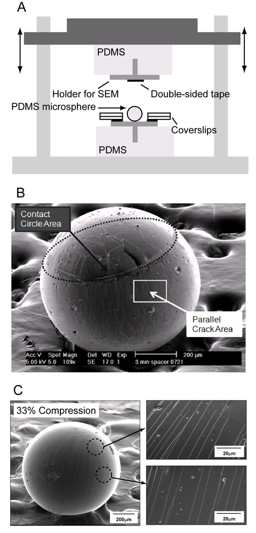
Figure 2.
A) The device for controlled compression of the microspheres. A microsphere is compressed between a movable mount and a static stage. Double-sided tape is attached only on the upper mount. Compression between adhesive (upper) and nonadhesive (lower) surfaces enables selective adhesion of the microsphere to the upper mount after relaxation. Coverslips were used as spacers to determine the amount of compression. B) SEM image of a microsphere that has been compressed by 79%. The contact circle area (2D random orientation of cracks) and the area between the two contact circles (parallel cracks running from pole to pole) are marked with arrows on the image. C) Additional SEM images showing the cracks generated at a compression ratio of 33%, showing that the crack spacing is essentially constant throughout the region between the contact and equator.

