Abstract
This paper presents the clinical motivation, design specifications, kinematics, statics, and actuation compensation for a newly constructed telerobotic system for Minimally Invasive Surgery (MIS) of the throat. A hybrid dual-arm telesurgical slave, with twenty joint-space Degrees of Freedom (DoF), is used in this telerobotic system to provide the necessary dexterity in deep surgical fields such as the throat. The telerobotic slave uses novel continuum robots that use multiple super-elastic backbones for actuation and structural integrity. The paper presents the kinematics of the telesurgical slave and methods for actuation compensation to cancel the effects of backlash, friction, and flexibility of the actuation lines. A method for actuation compensation is presented in order to overcome uncertainties of modeling, friction, and backlash. This method uses a tiered hierarchy of two novel approaches of actuation compensation for remotely actuated snake-like robots. The tiered approach for actuation compensation uses compensation in both joint space and configuration space of the continuum robots. These actuation hybrid compensation schemes use intrinsic model information and external data through a recursive linear estimation algorithm and involve compensation using configuration space and joint space variables. Experimental results validate the ability of our integrated telemanipulation system through experiments of suturing and knot tying in confined spaces.
Keywords: Dexterity Enhancement, Continuum Robots, Tele-Manipulation, Redundancy resolution, Suturing
1 Introduction
Minimally Invasive Surgery (MIS) benefits patients with reduced trauma and healing time by providing surgeons with access to patients’ internal organs via a limited number of access ports. These access ports constrain MIS instruments to only four DoF and limit their distal dexterity. To help surgeons overcome these difficulties, a large number of robotic devices and systems have been designed for MIS. Comprehensive reviews of these systems, and others, was given in (Howe and Matsuoka 1999; Taylor and Stoianovici 2003).
Since distal dexterity of surgical tools is a necessary enabler for complex operations in MIS (e.g. intracorporeal suturing), it received considerable attention from the medical robotics research community. Table I lists some of the existing literature on distal dexterity enhancement in MIS. The designs of instruments for distal dexterity include planar and spatial linkages, parallel wrists, serial articulated wrists, and snake-like devices. Target clinical applications for robotically enhanced distal dexterity in MIS are listed in Table II. These clinical applications include laparoscopy, arthroscopy, gastrointestinal surgery, neurosurgery, fetal surgery, microsurgery, needle steering, and ENT surgery.
Table I.
Previous Literature on Distal Dexterity Enhancement
| Linkages | (Minor and Mukherejee 1999; Yamashita et al. 2003) | Articulated wrists | (Schenker et al. 1995; Madhani, Niemeyer and Salisbury 1998; Guthart and Salisbury 2000; Asai et al. 2004) |
| Parallel wrists | (Reboulet and Durand-Leguay 1999; Piers, D. Reynaerts and Brussel 2000; Merlet 2002) | Snake-like robots | (Reynaerts, Peirs and Van Brussel 1999; Ikuta, Yamamoto and Sasaki 2003; Piers et al. 2003; Simaan, Taylor and Flint 2004; Harada et al. 2005) |
Table II.
Literature on Distal Dexterity Enhancement Listed by Medical Application
| Laparoscopy/arthroscopy | (Dario et al. 1997; Madhani, Niemeyer and Salisbury 1998; Cavusoglu, Villanueva and Tendick 2001; Yamashita et al. 2003) |
| Gastro-intestinal surgery | (Dario et al. 1999; Reynaerts, Peirs and Van Brussel 1999; Phee et al. 2002) |
| Microsurgery, Neurosurgery, fetal surgery | (Schenker et al. 1995; Mitsuishi et al. 1997; Ikuta, Yamamoto and Sasaki 2003; Asai et al. 2004; Harada et al. 2005) |
| Needle steering | (Okazawa et al. 2005; Webster et al. 2006; Sears and Dupont 2007) |
| Deep Surgical Fields Upper airways/ENT | (Ikuta, Yamamoto and Sasaki 2003; Simaan, Taylor and Flint 2004; Simaan, Taylor and Flint 2004; Kapoor, Simaan and Taylor 2005; Simaan 2005) |
Wrists for dexterity enhancement offered a partial solution to the distal dexterity problem and proved to be successful in laparoscopy. For example, Intuitive-Surgical offers a wide range of Ø5 and Ø 8 mm wire-actuated wrists (EndoWrist®), based on the designs of (Guthart and Salisbury 2000) and (Cooper et al. 2004). These wrists provide three wrist DoF in addition to the traditional four DoF of MIS instruments.
Despite the large number of previous works, current robotic instruments are still too large and/or have insufficient dexterity for some clinical applications. Cavusoglu showed in (Cavusoglu, Villanueva and Tendick 2001) that certain wrist designs are optimal for shallow suturing approach angles (as in thoracoscopy) while other wrist designs are suitable for steep approach angles (as in laparoscopy). (Cost-Maniere et al. 2001; Adhami and Maniere 2003; Cannon et al. 2003) also showed that it is beneficial to optimize the location of the access ports in MIS to ensure optimal performance using existing robotic systems such as the da Vinci system. (Faraz and Payandeh 2003; Simaan, Taylor and Flint 2004; Simaan 2005) showed that snake-like devices offer better dexterity than articulated wrists.
Clinical applications characterized by deep and narrow surgical fields are beyond the capabilities of existing commercial surgical systems due to size and dexterity limitations. Examples of such challenging clinical applications include neurosurgery, fetal surgery, skull base surgery, and MIS of the throat and the upper airways. Of these challenging clinical applications we chose MIS of the throat since it requires dexterous operation inside the throat while using the patient’s mouth as a pre-determined access port. This target clinical application shares much in common with newly arising surgical approaches such as single port surgery (Less Invasive Surgery (LIS)) and Natural Orifice Trans-luminal Endoscopic Surgery (NOTES) in which surgeons try to eliminate or reduce the number of access ports used.
This paper presents our integrated robotic system for MIS of the throat and the upper airways. This system includes a da Vinci master, a stereoscopic capture and display subsystem along with our dual-arm robotic slave. The dual-arm robotic slave of this system has twenty DoF and implements both kinematic and actuation redundancy for distal dexterity enhancement using miniature multi-segment continuum robots. Section 2 presents the driving clinical motivation, section 3 presents the design and performance specifications for our system, section 4 presents the system overview, section 5 presents the kinematics of the dual-arm slave robots, section 6 presents the statics and a novel method for actuation compensation for multi-segment continuum robots. Finally, section 7 presents our preliminary experience using the first integrated telemanipulation prototype of our system.
The contribution of this paper is in presenting the kinematics of our integrated telerobotic system and a method for actuation compensation and telemanipulation of multi-segment snake-like continuum robots. This method allows successful implementation of a special mode of operation that allows suturing in extremely confined spaces and involves rotation about the backbone curve of the multi-segment continuum robots. The paper also presents the telemanipulation framework used in our system with preliminary experimental validation of the integrated telerobotic system through demonstrations of dual-arm suturing and intracorporeal knot tying in confined spaces.
2 Clinical Motivation
The upper airway is a long, narrow, and irregularly shaped organ that includes the pharynx (throat), hypopharynx, and larynx, commonly referred to as the voice box. These areas are subject to a variety of benign and malignant growths, paralysis, and scar tissue formation requiring surgical interventions for excision and/or reconstruction. These procedures (e.g. partial or total laryngectomy, vocal fold repositioning, and laryngotracheal reconstruction) are routinely performed using open surgical techniques at the expense of damaging the integrity of the framework supporting the laryngeal cartilage, muscle, and the connective tissue vital to normal function. Minimally invasive endoscopic procedures are generally preferred over open procedures, thereby, preserving laryngeal framework integrity, promoting faster recovery and frequently overcoming the need for tracheostomy. Open surgery of the larynx provides good exposure and dexterity of instrumentation; however, healthy tissue, especially the delicate framework of the larynx, is often damaged by this approach. In contrast, endoscopic laryngeal surgery utilizes natural body openings and therefore minimizes trauma.
Other than minor advancement in tooling (e.g. the powered microdebrider (Myer et al. 1999; Patel, Rowe and Tunkel 2003)), endoscopic laryngeal surgery has evolved little in the past thirty years. As seen from Figure 1, the surgery is performed using an array of long instruments (180 to 250 mm for laryngeal and 240–350 mm for subglottic and tracheal surgery) through a laryngoscope that is inserted into the patient’s mouth and serves as a visualization tool and a guide for surgical instrumentation. Laryngologists remain restricted by the operator’s distance from the surgical field, the laryngoscope’s relatively small exposure, and reduced depth perception. These combine to restrict the surgeon’s ability to manipulate instruments across the long distance from the oral cavity to the larynx, resulting in poor sensory feedback (both visual and tactile) and magnification of the operator tremor. While microsurgical instruments have been miniaturized, they otherwise remain unchanged. They still have long handles and lack distal dexterity, which often results in damage to surrounding healthy tissue and limits healing from surgical trauma in endoscopic laryngeal surgery.
Figure 1.
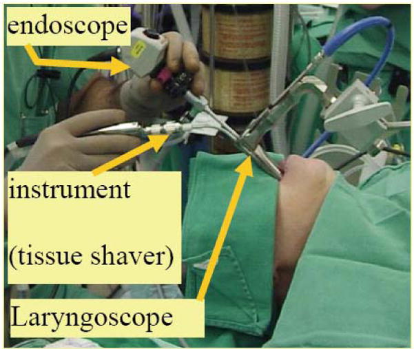
A typical surgical setup
Though (Woo et al. 1995; Plinkert and Lowenheim 1997) established distinct laryngeal endosuture techniques, suture repair of vocal fold wounds remains challenging and has yet to be accepted due to technical complexities and increase in operative time. The inability to suture such wounds results in larger scar formation. A recent study by (Fleming, McGuff and Simpson 2001) demonstrated a 75% larger scar area when laryngeal defects were healed with secondary intention vs. primary intention. A larger scar, likely due to unhindered collagen deposition, results in worse voice outcomes. At this time, endoscopic laryngeal surgery has reached an impasse as the lack of distal instrument mobility, complexity of suture technique and poor three-dimensional (3D) viewing field limit surgical techniques that are routine in other surgical subspecialties. Our current work addresses these needs by developing a tele-robotic system to allow surgeons to perform complex functional reconstruction tasks and suturing in MIS of the upper airway.
3 Design and Performance Specifications
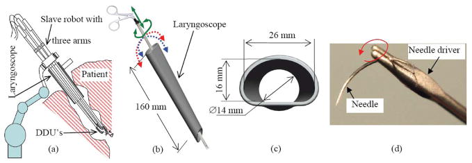
The clinical task requirements drove the design and performance specifications of our robotic slave for MIS of the throat. We adopted the standard manual setup of Figure 1 in which a laryngoscope is used to access the anatomy and to support an endoscope for visualization of the surgical field. Based on the dual-arm operation observed during surgery (e.g. Figure 1), a three-armed slave robot design was conceived in which two robotic arms are used for manipulation and a third robotic arm is used for suction, Figure 2-(a). The individual design of each robotic arm was guided by the specific limitations of MIS of the throat and the upper airways as shown in Figure 2-(b–c). The narrow and long laryngoscope reduces the traditional four DoF of minimally invasive tools to only two unconstrained DoF (translation along and rotation about the longitudinal axis of the robotic arms). The two remaining DoF of tilting are severely limited and provide limited motion inside the throat.
Figure 2.
(a) Our original concept for a three-armed robot with three Distal Dexterity Units (DDU’s) included two robot arms for manipulation and a third arm for controllable suction, (b) A rigid instrument passing through a laryngoscope is afforded only two unconstrained DoF out of the four DoF of rigid tools in MIS. (c) Cross sectional dimensions of a typical laryngoscope, (d) A semi-circular needle held by a needle driver.
In addition to these considerations, we use the fact that surgeons use semi circular needles for suturing by using rotation about the longitudinal axis of needle drivers as shown in Figure 2-(d). To achieve the task of passing the suture with minimal translation, rotation about the longitudinal axis of the gripper is desirable. Hence, our design specification for the DoF of the DDU’s called for at least four DoF including one DoF of rotation about the gripper’s longitudinal axis.
Specifications of the desired reachable workspace were derived from the anatomical limitations of the throat, table III. Other specifications of the required precision, speed, and forces were derived from in-vivo observations of several procedures and measurements done using existing surgical needle drivers. The orientation workspace was specified to allow desirable distal dexterity inside the throat while delivering desirable rotation about the longitudinal axis of the gripper for suturing. The maximal gripper force was specified to ensure stabilization of triangular cross section semi circular needles such as the one in Figure 2-(d). This gripping force was determined experimentally using standard needle drivers. Finally, the specifications for precision were such to allow accurate reconstruction of tissue (e.g. vocal folds).
Table III.
Task Specifications Used in the Design of the Robotic Slaves
| Reachable workspace | Orientation workspace | Maximal Speed |
|---|---|---|
| Ø 40 mm cylinder 50 mm long located 180–250 mm axially down the throat | ±90° pitch and yaw and ±180° roll about longitudinal axis of the gripper. | Bend each snake segment ±90° in 1 second |
| Precision | Tool tip forces | Gripper forces |
| ±0.5 mm translation, ±1° in orientation. | 1 N force in any direction | 40 N jaw clamping force. |
4 System overview
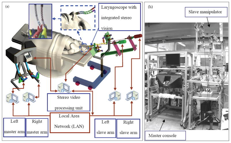
To address the challenges of MIS of the throat and upper airways, we designed and constructed the prototype tele-robotic system of Figure 3. This system includes an Intuitive Surgical da Vinci master interface equipped with 2D and 3D displays, a novel high dexterity dual arm robotic slave, and a teleoperation system capable of providing bi-lateral teleoperation.
Figure 3.
(a) An outline of the telerobotic system for MIS of the throat and upper airways, (b) The system prototype
The telemanipulation system shown in Figure 3 is comprised of a network of computers connected through a local area network. Each computer is connected to one robotic arm and runs an instance of the teleoperation control using an admittance-type slave robot and an impedance-type master. The control includes a low level position servo and a high-level controller. The high-level controllers communicate with each other, and thus the state of the connected robots is available to the high-level controller. Currently the state of the other slave is used by the high-level controller for collision avoidance. A fifth computer hosts the image and display acquisition hardware. A stereo laparoscope is connected to two image capture cards, and a dual video stream is generated for a surgeon display (a Head Mounted Display (HMD), a 2D display, or a 3D display can be used). Though currently no image processing is performed, our future goal is to allow the high-level controllers to incorporate information from the video processing unit. Using a separate controller for each robotic arm allows modular expansion of the system, such as addition of a third slave arm, with minimal changes to the existing system.
4.1 Dual-arm robotic slave for MIS of the throat
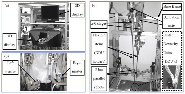
A bi-manual design of the slave robot was chosen to enable tissue functional reconstruction operations such as suturing and intra-laryngeal knot tying, Figure 4-(c). This design is a simplification of the initial three-arm concept depicted in Figure 2-(a) since the function of the third suction arm in Figure 2-(a) can be replaced by a flexible tube that is temporarily manipulated by one of the two remaining robot arms. The bi-manual slave robot of Figure 4-(c) is composed of two similar robotic arms, two identical parallel robots (five bar mechanisms), two cylindrical actuators (z-θ stages), and a base frame.
Figure 4.
(a) the user 2D and 3D display console, (b) the da Vinci master interface used in our system, (c) the dual arm slave manipulator for MIS of the throat
Each robotic arm is comprised of an actuation unit connected to a Distal Dexterity Unit (DDU) through a flexible stem (DDU holder). Each actuation unit controls one DDU and its gripper. The DDU is used to provide the necessary dexterity inside the throat. The DDU holder is a flexible channel that serves several purposes. First, it transmits mechanical actuation to the DDU. Secondly, it allows remotizing the actuation units from the entry point to the laryngoscope in order to provide easy visualization of the larynx. Thirdly, it allows to accommodate the size of the actuation units, which when placed next to each other require an opening bigger than the opening of a laryngoscope.
The z-θ stages provide rotation about and translation along the longitudinal axis of their corresponding DDU holders. This rotation about the axis of the DDU holder is converted by the DDU into rotation about the longitudinal axis of the gripper through a special mode of operation called rotation about the backbone. This generalization of the operation described in Figure 2-(d) is explained in detail in section 4.2.
The five-bar parallel robots provide precise control of the DDU holder inside the laryngoscope. Although we considered using the parallel robots to manipulate the actuation units (Simaan et al. 2007), we reconfigured our experimental setup as in Figure 4-(c) due to collision problems between the moving actuation units. In the current setup the actuation units are rigidly fixed to a stationary base frame and five-bar parallel robots use the flexibility of the DDU holders in order to precisely manipulate the distal ends of the DDU holders.
Each robotic arm has seven actuated joints used to control the DDU and its gripper while providing actuation redundancy to optimize the load between the actuating members of the DDU, (see section 6.1). The complete dual-arm robotic slave has twenty actuated joints that provide the necessary collision avoidance between the DDU holders while imparting six DoF of task-space motion to each gripper. Two additional controlled joints are used for controlling end effectors (grippers, dissectors, etc.).
4.2 Distal Dexterity Units (DDU’s)
Figure 5 presents the DDU of our system. It is composed from two flexible snake-like segments. Each segment is a flexible multi-backbone continuum robot. Earlier prototypes were composed from a single section snake-like robot and a flexible parallel robot at its tip (Simaan, Taylor and Flint 2004; Simaan et al. 2006). Due to limited dexterity and manufacturing constraints, we changed our design according to the prototype shown in Figure 5.
Figure 5.
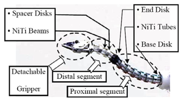
The Distal Dexterity Unit (DDU)
Each snake-like segment is composed from a base disk, several spacer disks, an end disk and four flexible super-elastic beams that we call backbones. The central backbone is rigidly attached to the base and the end disk of the segment, Figure 5. This backbone is called the primary backbone. The three other backbones are called secondary backbones and they are circumferentially and equidistantly distributed around the central backbone. All secondary backbones are connected only to the end disk. The spacer disks maintain a fixed radial distance between the secondary backbones and the primary backbone. The distal segment of the DDU is similar to the proximal segment with the exception that its backbones are thin beams that pass through the tubular backbones of the proximal segment.
By actively changing the lengths of two out of the three secondary backbones, the end disk of each segment can be oriented in any direction. Instead of the minimal number of two actuated secondary backbones, three secondary backbones are actuated in each DDU segment. This allows for optimal load distribution among the DDU backbones by using actuation redundancy. Also, each DDU is capable of transmitting rotation about its backbone. This rotation about the backbone mode of operation is demonstrated in Figure 6. The DDU of Figure 5 provides four DoF of motion since it has two segments. The added capability of transmitting rotation about the DDU backbone allows using the rotation about and the translation along the axis of the DDU holder in Figure 4-(c) to provide the gripper with six motion DoF while enabling suturing through rotation about the longitudinal axis of the gripper in any direction within the orientation workspace of the DDU.
Figure 6.
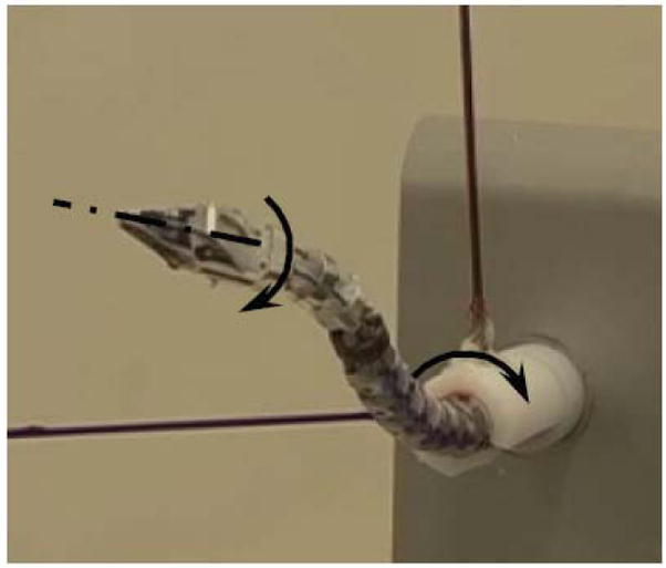
The DDU’s were designed to transmit rotation along their backbone
The advantages of this design include enhanced miniaturization and payload carrying capability. This advantage stems from the bidirectional actuation of the secondary backbones (push-pull actuation) compared to the unidirectional actuation using wires. Another advantage is backlash elimination by disposing of small pivots and gears used in articulated designs. Further advantages include MRI compatibility (since the snake is made from NiTi and the disks are from Al), and support of multiple modalities of use including drug/light/laser delivery through the tubes of the secondary backbones. Our slave robot is not designed to be MRI compatible, but the design of the DDU’s can be adapted for potential applications requiring MRI compatibility (e.g. Neurosurgery).
The push-pull actuation of the secondary backbones provides actuation redundancy that allows optimization of the load on all backbones in order to support enhanced payload carrying capability despite miniaturization. In (Simaan 2005) it was shown that different actuation redundancy schemes can reduce the compressive load on the backbones while providing improved load carrying capabilities compared to wire-actuated designs using a flexible central backbone. The current design of our snake has spacer disks 4.2 mm in diameter and a pitch diameter of 3.0 mm (the diameter of the circumference around which the secondary backbones are distributed). The length of the proximal segment is 23 mm and the length of the distal segment is 12 mm. The diameter of the proximal segment backbones is 0.635mm (outer diameter) and 0.508 mm (inner diameter). The diameter of the backbones of the distal segment is 0.406 mm. The minimal bending radius that corresponds to 5% strain in the superelastic backbones is 12.7 mm for the proximal segment and 8.13mm for the distal segment. This strain limit was established based on our experimental evaluation and recent literature on fatigue of super-elastic wires (e.g. (Nemat-Nasser and Guo 2006)).
4.3 DDU Actuation Unit
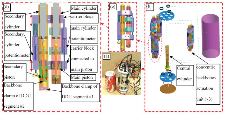
Each segment of the DDU is actuated using three secondary backbones. The DDU gripper requires one additional actuated joint. Hence, we designed a compact actuation unit having seven controlled joints. Since the backbones of the distal segment of the DDU pass through the backbones of the proximal segment, a compact design that allowed actuating two coaxial backbones was required. The actuation unit is composed from three similar two DoF actuation units that are radially arranged around one central cylinder, Figure 7. Each two DoF actuation unit drives a pair of concentric secondary backbones. The outer backbone is the secondary backbone of the proximal segment of the DDU. The inner backbone is the secondary backbone of the distal segment of the DDU. The central cylinder is used to actuate the detachable gripper.
Figure 7.
A seven DoF actuation unit for a two-section snake-like Distal Dexterity Unit (DDU) with a detachable gripper: (a) the assembled prototype, (b) an exploded view, (c) actuation unit for two coaxial backbones, (d) cross section of the two DoF actuation unit of two coaxial backbones.
Each concentric backbone’s two DoF actuation unit is composed from a main cylinder and a secondary cylinder. The main cylinder controls a secondary backbone of the proximal DDU segment while the secondary cylinder controls a secondary backbone of the distal DDU segment. The secondary cylinder is carried on two carrier blocks that slide along the axis of the main cylinder. One of these carrier blocks is connected to the piston of the main cylinder through a shear pin. When the position of the main piston is controlled, the secondary cylinder is moved up and down to control the secondary backbones of the proximal segment of the DDU. The piston of the secondary cylinder is actuated independently in order to actuate the secondary backbone of the distal DDU segment.
5 Kinematics of the dual-arm slave robot
This section presents the kinematics of the dual arm slave robot of Figure 4-(c). Part of these results have been presented in (Simaan, Taylor and Flint 2004) for the DDU kinematics. The overall kinematic architecture of one robotic arm of the slave robot includes serial and parallel kinematic mechanisms and flexible components.
The flexible stem of the DDU holder moves inside the limited cross section of the laryngoscope. This geometric constraint corresponds to a deflection range of less than ±40 mm over a flexible stem that is about 800 mm long. Therefore, we adopt the simplified linear beam deflection model to describe the kinematics of the flexible DDU holder.
In addition, we make an assumption that the gravitational energy of the DDU is negligible compared to its elastic energy. This assumption is further tested and justified in section 6.1. The friction between the spacer disks and the secondary backbones is also neglected. This friction was minimized through proper design of the height of the spacer disks to minimize friction effects and to eliminate mechanical lock. Our experiments indicate that this assumption is reasonable as evident from our ability to easily move the spacer disks axially along the central backbone of the DDU; even when the DDU is bent at a general configuration.
5.1 Kinematic Nomenclature
We will use the following nomenclature throughout the paper.
{A} - A right handed coordinate frame with {x̂a, ŷa, ẑa} as its associated unit vectors.
CvA/B, CωA/B - linear and angular velocities of frame {A} with respect to frame {B} expressed in frame {C}. Unless specifically stated, all vectors in this work are expressed in World Coordinate System (WCS) {0}.
ȧ time derivative of a
C ẋA/B - Twist♣ of frame{A} with respect to frame {B} expressed in frame {C} CẋA/B = [CvA/BT, CωA/BT]T.
A RB - Rotation matrix of frame {B} relative to frame {A}.
(a)^ - Skew-symmetric cross-product matrix of vector a such that a × b = (a)^b.
Apab -A position vector pointing from point a to point b, expressed in frame {A}.
Jxy - A Jacobian matrix such that [Jxy] i, j = ∂xi/∂yj
qzθ = [qzθ1,qzθ2]T the vector of joint variables for the z-θ stage (first joint is prismatic, second joint is revolute)
q5bar = [q5bar1,q5bar2]T the vector of active joint variables for the five-bar parallel robot
qsj = [qsj1,qsj2qsj3]T the vector of active joint variables for DDU segment j.
Ψj = [θLj,δj]T, j=1,2, represents the configuration variables of the jth segment of the DDU where θLj is the bending angle of the jth segment of the DDU, j=1,2 and δj is the angle characterizing the plane in which the jth segment of the DDU bends with respect to the unit vector the central backbone with the first b, j=1,2, Figure 8.
θ0j - the angle of the backbone tangent in the bending plane of the jth DDU segment as shown in Figure 8. θ01 = θ02 = π/2.
Lj – length of the central (primary) backbone of DDU segment j. j=1,2.
Lsi – length of the secondary backbone of an arbitrary DDU segment. i=1,2,3.
Figure 8.
kinematic nomenclature for the j’th segment of the DDU: (a) A projection of one secondary backbone and the primary backbone on the segment bending plane, (b) top view of the base disk of the DDU segment, (c) the definition of the angle δj at a fully extended configuration is based on the desired (commanded) linear velocity (or angular velocity) of the end disk.
5.2 Kinematics of a single DDU segment
Figure 8 shows one segment of the DDU (we assume it is the j’th segment). Since the DDU segment is a continuum robot, its shape is given by its minimal elastic and potential energy. When the secondary backbones are actuated, the snake segment bends in a plane perpendicular to the base disk of the segment. This planar bending occurs since all backbone curves remain parallel to each other and because the gravitational energy of the DDU segment is negligible (see section 6.1 for details). The position and the orientation of the end disk of the DDU segment with respect to the base disk are therefore parametrized by two configuration variables δj and θLj as defined in the nomenclature and in Figure 8.
The angular coordinate σi of each secondary backbone about ẑb is related to δj according to Eq. (1) and Figure 8-(b).
| (1) |
The radius of curvature of the central backbone is ρ(s) where s is the arc length measured from the base disk. The projection of the i’th secondary backbone on the segment bending plane is a curve, which is offset by Δi = r cos(σi) from the primary backbone. The radius of curvature and arc-length of this curve are respectively ρi(si) and si. The radius of curvature of the primary backbone is related to the radius of curvature of the i’th secondary backbone according to Eq. (2).
| (2) |
Using Eq. (2)., yields the result of Eq. (3) for the length of the i’th secondary backbone Lsi.
| (3) |
Substituting the definition of the joint value qsji = Lsi − Lj, in Eq. (3) yields the angle θLj:
| (4) |
Since all the local tangents of the backbones are always parallel to each other, one may use Eq. (4) for backbones 1 and 2 to define a kinematic compatibility condition of achieving the same θLj as one traverses backbone 1 and backbone 2. This kinematic compatibility condition, Eq. (5), also holds for any pair of secondary backbones.
| (5) |
Eq. (5), is used to solve for the angle δj of the segment bending plane:
| (6) |
where atan2 follows the convention θ = atan2(sin(θ),cos(θ)).
For a given vector of joint values qsj, the segment configuration Ψj = [θLj δj]T is given by Eqs. (4) and (6). The time derivative of Eq (4) for i=1,2,3 yields the Jacobian relating configuration space and joint space speeds:
| (7) |
Note that rank (JqΨj)=2 in all the whole configuration space.
The position, pL, and the orientation, bRe, of the end disk with respect to the base are found by integrating along the tangent of the backbone and by a successive rotation sequence as in Eq. (8). The matrix bR1 is a rotation matrix of (−δj) about ẑb and 1Re is a rotation matrix of (θ0j − θLj) about ŷ1, Figure 8.
| (8) |
The shape of the backbone is a function of θLj and θ(s) = f(θLj,s). By taking the time derivative of this function one obtains a distribution of bending speed along the backbone as a function of the bending speed of the tip. This distribution is designated by g(θLj,s), Eq. (9).
| (9) |
Taking the time derivative of Eq. (8) results in the configuration space inverse kinematics Jacobian JxΨj where ẋj ∈ ℜ6×1 is the twist of the end disk of DDU segment j with respect to the center of its base disk.
| (10) |
We use the approximation that the shape of the DDU at any configuration may be described by a circular segment. This approximation was validated in (Xu and Simaan 2008). The bending distribution function g(θLj,s) for a DDU that bends in a circular shape is g(θLj,s) = s/Lj. This distribution function results in the explicit expression for the Jacobian JxΨj:
| (11) |
Eq. (11) is ill-defined when θLj = θ0j = π/2. This singularity is resolved by applying L’Hopital Rule, as in Eq. (12). For this configuration, the angle δj of the DDU segment bending plane is defined based on the unit vector v̂desired of the desired (commanded) end disk linear velocity such that δj = atan2 (v̂ desired Tŷb,− v̂ desired Tx̂b). A comparison of Figure 8-(a) and Figure 8-(c) shows that this definition maintains consistency of δj as the bending angle θLj grows from zero to θ0j = π/2 (straight configuration).
| (12) |
5.3 Kinematics of one single robotic arm
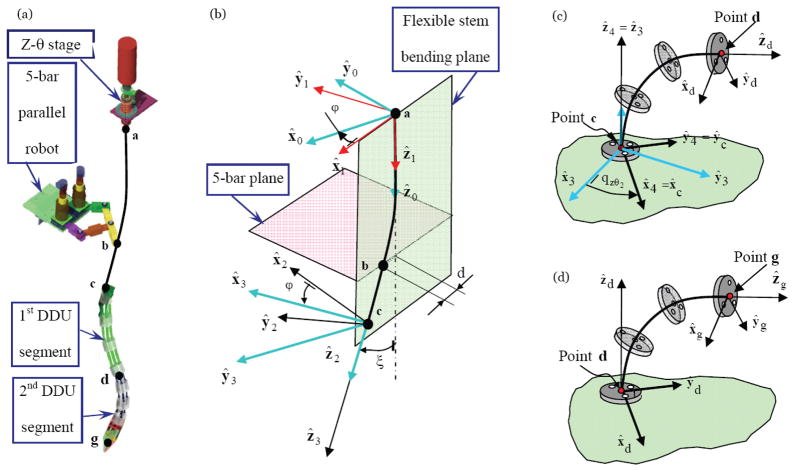
The kinematic nomenclature for one robotic arm of the slave robot is shown in Figure 9. The three serially attached portions of the robotic arm are the flexible stem (DDU holder) and two similar snake-like segments of the DDU. The manipulation of the flexible stem is achieved by passing it through a spherical joint (point b) that is manipulated by a planar five-bar parallel robot. The stem has an additional degree of freedom of sliding inside the bore of the spherical joint.
Figure 9.
Kinematic notations for a single arm of the surgical slave robot: (a) designation of points along the backbone of the arm, (b) kinematic notation for the flexible DDU stem, (c) kinematic notation for the proximal segment of the DDU, (d) kinematic notation for the distal segment of the DDU.
To describe the kinematics of one robotic arm an augmented vector q̇ = [q̇zθ T,q̇5bar T,Ψ̇1 T,Ψ̇2 T] ∈ ℜ8×1 is defined. The kinematic derivation proceeds with solving the kinematics of the flexible stem as a function of the five-bar and the z-θ stage. It is assumed that the flexible stem is rigid enough to deliver the rotation of the z-θ stage to its distal point (point c). This rotation is represented in Figure 9-(c) by an equivalent rotation of the base disk of the proximal segment of the DDU.
The kinematics of the five-bar parallel robot is described using its inverse kinematics Jacobian, Eq. (13). The derivation of this Jacobian for parallel robots is trivial using statics or derivatives of loop closure equations (Simaan, Glozman and Shoham 1998). For brevity this derivation is not included here. In Eq. (13) designates the two-dimensional linear velocity of the end effector (point b) in the plane of the five-bar.
When the flexible stem is bent using the five-bar parallel robot, its shape is characterized by the angle ϕ defining the plane in which it bends and the deflection angle ξ at its tip, Figure 9-(b). Since only a point force is applied at point b and the forces applied by the snake on the flexible stem are small, we neglect the deflection of bc since it is significantly shorter than segment ab. Using the linear elastic model, Eq. (14), for a beam subject to load F at point b, we are able to find the deflection angle as a function of the linear deflection d, Eq. (15). In Eq. (15) Lab designates the length of the stem from point a to point b, E designates Young’s modulus, I designates the bending moment of inertia of the beam. The angle of the bending plane ϕ is given by the deflection of the beam, Eq. (16)♠.
| (14) |
| (15) |
| (16) |
Three coordinate systems are defined in addition to WCS {0}, Figure 9-(b). These coordinate systems describe a rotation sequence that provides the orientation of the tip of a bent beam without considering the rotation caused by the z-θ stage. The rotation matrices defining these frames are:
| (17) |
| (18) |
| (19) |
The absolute velocity of point b as a function of the five-bar parallel robot kinematics (Eq. (13)) is described in {0} using the components of motion in the bending plane and the component perpendicular to the bending plane, Figure 9.
| (20) |
The velocity of point b perpendicular to the bending plane is also given by ϕ̇ as a result of the rotation of the bending plane about axis ẑ0, Eq. (21). Using Eq. (20) and Eq. (21) one obtains ϕ̇ as a function of the five-bar parallel robot kinematics, Eq. (23). In Eq. (23) the simplification 0ẑ×0x̂1 = 0ŷ1 was used to define .
| (21) |
| (22) |
| (23) |
By differentiating Eq. (15) with respect to time, one obtains the bending angle rate as a function of the five-bar robot kinematics, where Ad ≡ 0x̂1 TEJ5bar−1 ∈ ℜ1×2. In obtaining Eq. (24) the deflection rate ḋ= 0x̂1 TEJ5bar−1q̇5bar was used.
| (24) |
The relative velocity of point b with respect to {1} written in {1} is only in the direction of the deflection along x̂1, Eq. (25). This is due to the small deflection assumption in which the movement of point b in the ẑ1 is neglected. The relative angular velocity of segment bc in {1} is given by the rate of the configuration variable ξ, Eq. (26). Using the rigid body kinematics of segment bc one obtains the velocity of the tip of the flexible stem, Eq. (27).
| (25) |
| (26) |
| (27) |
The absolute velocity of the tip of the flexible stem (point c) is given by adding the velocity due to the rotation of {1}.
| (28) |
The absolute angular velocity of {3} is given by
| (29) |
Using Equations (28) and (29) we can find the Jacobian Js relating the joint speeds of the five-bar parallel robot with the twist of point {3}. Jsv and Jsω designate the linear and angular velocity Jacobians.
| (30) |
The z-θ stage contributes to the twist of the flexible stem by providing axial speed q̇zθ1 along and angular speed q̇zθ2 about ẑ2. To capture this we define frame {4} using a simple translation qzθ1 and rotation qzθ2 about and along ẑ3. We also assume that the base disk of the proximal DDU segment is attached to the flexible stem such that {4} = {c}. The Jacobian relating the contribution of the joint speeds of the z-θ stage to the twist of the flexible stem is given in Eq. (31). Superimposing the twist generated by the z-θ stage with the twist caused by the five-bar mechanism we obtain the kinematic model for the twist of the distal end of the flexible stem as it is described in terms of the kinematics of the five-bar and the z-θ stage, Eq. (32).
| (31) |
| (32) |
Two-dimensional configuration vectors Ψ̇j = [θLj, δj]T are used to describe the kinematics of the j’th segment of the DDU as defined in section 5.2, Eq. (33).
| (33) |
Using the twist transformations to account for the translation and rotation from the base of the distal DDU segment (point d) to the gripper (point g) one obtains the relative twist of the gripper with respect to the end point of the flexible stem, Eq. (34) where S1 and S2 are twist transformation matrices given in Eq. (35).
| (34) |
| (35) |
The absolute twist of the gripper in {0} is given by superimposing the relative twist in Eq. (34) with the twist of the flexible stem, Eq. (32) while accounting for the necessary twist transformations S3 and S4, Eq. (36).
| (36) |
| (37) |
Equations (32), (33), (34) are used to derive the overall kinematics Jacobian Jarm of a single robotic arm.
| (38) |
Equation (38) defines the inverse kinematics of a single robotic arm in terms of the augmented vector q̇ = [q̇zθT, q̇5barT, Ψ̇1T, Ψ̇2T]T ∈ ℜ8×1. The solution for individual joint speeds is obtained through kinematic redundancy resolution Eq. (39). The null space vector h can be used to satisfy obstacle avoidance or to maximize dexterity (Kapoor, Simaan and Taylor 2005). In Eq. (39) (Jarm)+ designates the generalized inverse. While other methods for obtaining redundancy resolution for Eq. (38) exist, we use the pseudo-inverse method. Our experience as indicated in section 7 suggests that this method works quite well for our application.
| (39) |
Each DDU segment has a Jacobian relating its joint rates (the backbone lengths) with the rates of its configuration variables (Simaan, Taylor and Flint 2004). Once Eq. (38) is solved, the joint rates q̇sj of each DDU segment (j=1,2) are calculated using Eq. (7).
6 Actuation compensation
Figure 6 introduced a desirable mode of operation of the DDU for suturing in confined spaces. We called this mode of operation rotation about the backbone. During this mode of operation, the desired configuration variables δj, j=1,2, must be precisely changed at the same rotation rate of the z-θ stage (Simaan 2005). To support rotation about the backbone, precise coordination of all actuation joints controlling the configuration vectors Ψj (j=1..2) of each DDU segment is essential to prevent wobbling of the gripper.
Despite its advantages mentioned in section 4.2, the design of the DDU presents several challenges. The long and flexible backbones introduce modeling uncertainties that include friction and flexibility in the actuation lines. Regardless of the method used to actuate the DDU (either using wire actuation or push-pull actuation), it is necessary to compensate for modeling uncertainties since there is no direct means to measure and provide closed loop control on the configuration vectors Ψj of the DDU segments. Instead, position control is carried out in joint space.
Each backbone connects to the actuation unit by passing through the long flexible stem of the DDU holder and dedicated channels in the actuation cone, Figure 10. Bending each segment of the DDU requires significant actuation forces that produce a significant axial extension along the long actuation path between the DDU and the actuation unit. To obtain the desired configuration Ψj of each DDU segment, the commanded joint vectors qj must be corrected using an actuation compensation vector εk that accounts for the backbone extension, friction, and backlash. Since actuation errors in the proximal segment directly affect the length of the backbones of the distal segment, Eq. (40) is used for the actuation compensation model.
Figure 10.
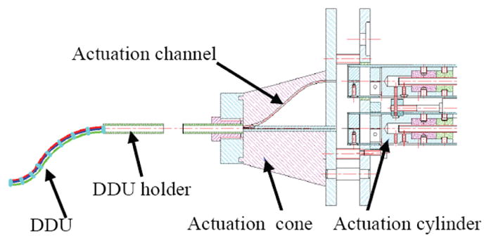
A schematic drawing of the snake-like unit and its actuation unit
| (40) |
Determining the actuation compensation vectors ε1 and ε2 may be carried out based on estimation schemes in joint space qj or in configuration space Ψj. In (Xu and Simaan 2006) we presented actuation compensation methods for a single DDU segment using model-based and combined model-based with recursive linear squares estimation methods. The following sections extend these results and provide joint-space and configuration space compensation algorithms for multiple segment DDU’s. The choice of what compensation algorithm to use depends on the availability of external data (e.g. visual tracking of the gripper) to update the recursive estimation approaches that use Ψj in the process.
6.1 Statics Modeling
The static analysis of the DDU is derived using the virtual work model. Twisting of backbones and the friction between spacer disk and the secondary backbones are neglected. Each snake-like unit in Figure 5 weighs 6.72 grams. Given the circular bending shape of the DDU segments, the ratio of gravitational energy to elastic energy as a function of the bending angle θL = θL1 = θL2 is plotted in Figure 11. The elastic energy of the j’th DDU segment is calculated based on the elastic bending energy of all the backbones, Eq. (41). Even when the robot is only bent to θL = θL1 = θL2 = 87° this ratio is as small as 0.0099 (0.99%). Hence gravity is neglected in the analysis. In Eq. (41) E stands for Young’s modulus of the superelastic NiTi backbones, Ip and Is are the bending cross sectional moment of inertia of the primary and the secondary backbones, L is the length of the primary backbone, Li is the length of the i’th backbone.
Figure 11.
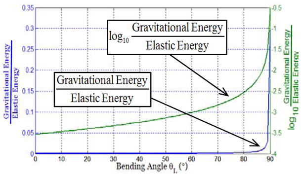
Gravitational energy over elastic energy ratio
| (41) |
The required actuation forces, τj, were found in (Simaan 2005) using the virtual work principle, which results the static equilibrium condition in Eq. (42).
| (42) |
In Eq. (42), We is the wrench acting on the end disk. These equations constitute two equations with a vector of three unknowns τj. The vector τj is found using the solution in Eq. (43). I hτ ∈ ℜ3×1 is a vector of homogeneous actuation forces used to optimize the loads on the backbones.
| (43) |
The vector of joint actuation forces τj is important for determining the required actuation compensation due to the backbone flexibility. Without loss of generality and for simplicity, we assume that I hτ ∈ ℜ3×1, i.e. we use the minimum-norm redundancy resolution for the following sections dealing with the actuation compensation methods.
6.2 Actuation compensation in joint-space
The model of backbones of segment j of the DDU includes two portions, Figure 10. The first portion is along the DDU holder and it is subject to forces vector τj ∈ ℜ3×1 that is determined based on the static model in Eq. (43). The second portion is along the actuation channel in the DDU actuation cone and it is subject to the force τj+fj where fj designates the vector of friction forces in the actuation channels of the DDU actuation cone. The model for fj in Eq. (44) is based on the resemblance of a bent backbone passing through an actuation channel in the DDU cone to the model on a band brake (Juvinall and Marshek 2003). In Eq. (44), φ represents the contact angle along the actuation channel, μ is the coefficient of coulomb friction, and fsj is the vector of static friction forces that results from bending the backbone along the curvature of the actuation channels. The values of φ, μ, and fsj were determined in (Xu and Simaan 2006).
| (44) |
The stiffness matrices representing the first and second portion of each backbone in the jth segment of the DDU are respectively designated by Ksj and Kcj, j=1,2. These matrices are given by the linear elastic model of the backbones, Eq. (45). In Eq. (45) Asj represents the area of the cross section of the secondary backbone of DDU segment j, Ls represents the length of the DDU holder, Lc represents the length of the actuation channel in the DDU cone and up to the connection point with the actuation unit.
| (45) |
The models of the stiffness and the forces acting on each portion of the backbones can be combined to produce a model for the extension vector εj for segment j, Eq. (46). In Eq. (46), ηj is a scale factor that corrects for uncertainties in the static model of the DDU due to uncertainties in material properties of the NiTi, λj compensates for backlash in the actuation lines of the jth segment of the DDU. The unknown parameters in Eq. (46) are λj and ηj. These parameters can be estimated using a recursive linear estimation approach by casting Eq. (46) in the standard form for recursive linear estimation as was shown in (Xu and Simaan 2006).
The linear estimation has to be carried out independently for each segment of the DDU while keeping all the other DDU segments straight and commanding the jth segment to bend at a desired angle θLj. The estimated vector in recursion k, [ηj[k], λj[k]]T, is refined by using the k’th measurement of the bending angle, θLj[k], to calculate the theoretical extension of the backbones εj. The calculation of εj is based on the inverse kinematics of the DDU segment as presented in (Simaan, Taylor and Flint 2004). Once the estimation of λj and ηj converge, εj is calculated using Eq. (46) and the corrected value of the joint command is found using Eq. (40).
| (46) |
This recursive estimation has been shown to converge in less than ten iterations while providing tracking errors of less than 1° for a single segment of the DDU, (Xu and Simaan 2006). The results of this compensation method are satisfactory for providing good tracking on the bending angles θLj of each segment of the DDU. Since the estimation is carried out using only the measurement of θLj while assuming that configuration angle δj does not require compensation, this approach does not work as well when trying to perform rotation about the backbone with multi-segment DDU. For this reason, we adopted another approach of directly applying the compensation in configuration space.
6.3 Combined configuration and joint-space actuation compensation
It is possible to apply the compensation in configuration space Ψj = [θLj,δj]T of the DDU segments prior to applying the compensation in joint space. For the two-segment DDU of Figure 5 this correction is applied on the vector .
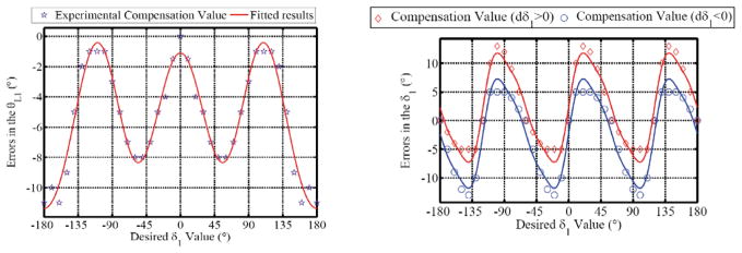
This method requires measuring the complete configuration vector Ψj = [θLj,δj]T of each segment of the DDU. This was achieved using a Micron® optical tracker, Figure 12. The compensation process was carried out serially while changing θLj in increments of 15° in [0°, 90°]. For each θLj, δj was changed in increments of 5° in [−180°, 180°]. For example, the compensation process for θLj=45° was implemented as the following: θLj was bent to 45° and δj was changed from −180° to +180°, the errors on θLj were recorded and fitted to a series of cosine functions of δj; this intermediate compensation was then implemented while θLj was bent to 45° and δj was actuated between −180° and +180°); the errors on δj were then fitted into a series of cosine functions of desired value of δj. It was noted that the errors on δj had different values when δj was actuated in clockwise or counterclockwise directions. Hence, the compensation has different expressions for the two actuation directions. Finally, this dual compensation can be written as in Eq. (47). dδj in Eq. (47) represents the desired incremental change in δj and its sign is used to determine the rotation direction of δj.
Figure 12.
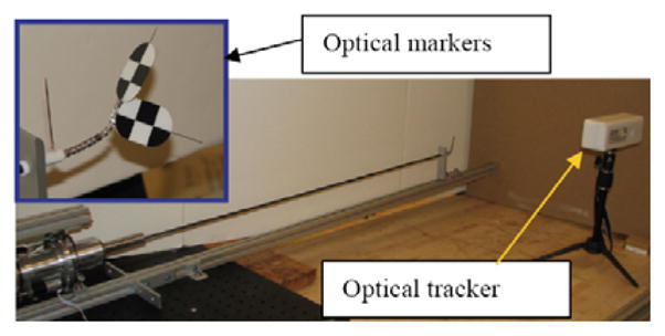
Experimental setup using optical tracker for compensation in configuration space.
| (47) |
| (48) |
| (49) |
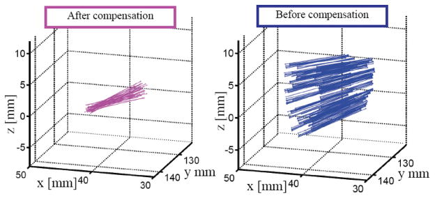
In the implemented compensation, the corrected configuration vector is obtained as Ψ̃j = Ψj + ΔΨj. The corrected configuration vector Ψ̃j is substituted back to the joint space compensation equation (Eq. (40)) to achieve desired motion tracking. Figure 13 compares the result of Eq. (47) for θL1 and δ1 with the observed errors. It is clearly seen that the experimental values for both θL and δ agree with the fitting produced by Eq. (47). Figure 14 shows the results of this compensation used to perform rotation about the backbone of the two-segment DDU of Figure 5. Figure 15 shows the movement of the longitudinal axis of the gripper with or without compensation. The DDU during this experiment was bent such that θL1 = θL2 = 30° (60° bending) and δ1 was varied from 0° to 720° while δ2 was varied from −45° to 675°. The different starting points for δ1 and δ2 were due to the fact the proximal and distal DDU segments were not coplanar (the DDU was bent into a spatial S shape). The results of Figure 15 show that when no compensation was used, the axis of the gripper wiggled within an elliptical cone ±3.5° in horizontal direction and ±5.7° in vertical direction. When compensation was applied, the wiggle was reduced to less than ±1.5° in all directions. The accuracy of the tracker and the markers used during the configuration space compensation was ±1.2°. This demonstrates the effectiveness of our approach since the algorithm almost converged within the tracking error of the tracker used to define the actuation compensation model.
Figure 13.
Experimental errors in both δ1 and θL1 plotted with respect to desired δ1 when desired 45 θ̂L1 = 45°
Figure 14.
Rotation about the backbone with and without actuation compensation
Figure 15.
Spatial motions of the longitudinal axis of the gripper during a rotation about the backbone of the DDU.
7 Preliminary Experience
Figure 16 shows our most recent experiments on passing a circular suture through a mockup setup and performing knot tying using the telemanipulation system prototype of Figure 3. The figure shows that the surgeon using the master manipulator was able to effectively pass sutures and tie knots using the telemanipulation system of Figure 3. The details of the telemanipulation used in this system were presented in (Kapoor et al. 2006) and will not be repeated here for space considerations.
Figure 16.
Tele-manipulation experiments showing (a) passing a circular suture, (b) bi-manual knot tying. Extension 1 presents a video of the knot tying process using the robotic system of figure 3.
We experimentally determined the flexibility of the DDU’s and we noticed that the lowest bending stiffness of the DDU is when it is fully extended. This stiffness is about 0.5 N/mm. Since the side forces applied by the DDU are no more than 1 N, we did not experience major deflections that prevented the surgeon from being able to use the system effectively. The repeatability of the slave robot using the actuation compensation is 1° in orientation and 0.5 mm in positioning. This repeatability, however, is not maintained when the DDU performs rolling motion about its backbone. The observed repeatability after actuation compensation is better than ±1.5° in orientation and ±0.8 mm in positioning. This repeatability depends on the accuracy of the tracker used during the actuation compensation calibration experiments.
The maximal bending rates of the DDU’s were validated. Our experience shows that the DDU’s proximal segments were able to bend 90° in 1sec in any direction. The distal segments were able to bend 60° in any direction within 0.3 sec. The time for tying a knot depends heavily on the user and his familiarity with the master interface and the visualization interface used. The users were not able to complete a knot using a 2D display. When using a 3D display, the estimated time for passing a suture was 10 sec and the time for tying a knot was 18 sec (see Extension 1 for a video of knot tying).
8 Conclusions
Despite the efforts of the robotics community to provide robotic assistance for MIS, there are some challenging areas that do not yield to existing robot designs due to limitations on dexterity, size, and availability of suitable DoF. One of these challenging areas (namely MIS of the throat) was addressed in this work. The clinical motivation driving our research highlights the importance of intracorporeal knot tying and suturing in order to effectively enable various minimally invasive procedures for the throat.
A novel design of dual arm robotic slave with twenty joint-space DoF was presented. This robotic slave was designed to provide dexterity through the use of continuum snake-like robots (Distal Dexterity Units – DDU’s). The kinematics of the system includes flexible continuum robots (the DDU’s) and flexible stems manipulated by five-bar parallel robots. The statics and actuation compensation supporting enhanced miniaturization, increased payload carrying capability, and precision tracking were presented. Specifically, a special mode of operation suitable for intracorporeal suturing was presented. This mode of operation involves using the snake-like robot (DDU) to provide rotation about the longitudinal axis of the gripper by transmitting rotation from its base along its central backbone. Successful execution of this mode of operation is predicated on a precise synchronous actuation of all backbones actuating the continuum robot (DDU). A method for actuation compensation was presented in order to overcome uncertainties of modeling, friction, and backlash. This method uses a tiered hierarchy of two novel approaches of actuation compensation for remotely actuated snake-like robots. The first tier of our actuation compensation uses intrinsic joint-space information together with extrinsic pose measurement of the DDU in order to provide a linear recursive estimation of the compensation parameters. The results of this first tier are suitable for single segment DDU’s. In order to account for coupling effects among adjacent DDU segments, a second tier of actuation compensation was presented. This second tier uses configuration space compensation approach in order to provide precise actuation compensation for multi-segment flexible snake-like robots (DDU’s).
The design specifications, kinematics, control, and actuation compensation presented in this paper have been experimentally validated on an integrated prototype telemanipulation system that includes a da Vinci master, a stereoscopic capture and display subsystem along with our dual-arm slave. All the components of this prototype system were tested to work in conjunction with each other under realistic surgical task scenarios. These experiments show that the compensation algorithms presented can support rotation about the central backbone of complex multi-segment continuum robots and that the accuracy of the compensation is close to the error of the extrinsic information used to calibrate the actuation models. Telemanipulation experiments show that the prototype system is capable of passing sutures in constrained spaces such as the throat. Future work will include experiments and performance validation of the prototype system in performing specific surgical tasks for throat surgery in animal or cadaver models.
The methods presented in this paper were designed specifically for our system. However, these methods extend to robotic systems that use flexible members, systems that use mechanically remote actuation of snake like robots (e.g. MRI compatible robots), and any telemanipulation system that uses high DoF snake-like slaves for telemanipulation.
Supplementary Material
Acknowledgments
The work reported in this paper was funded in part by the National Science Foundation (NSF) under Engineering Research Center Grant EEC9731748 and NSF Grant IIS9801684, in part by the National Institutes of Health (NIH) under Grant R21 EB004457-01, and in part by Johns Hopkins University and Columbia University internal funds.
Appendix A: Appendix of Multimedia Extensions
The multimedia extension page is found at http://www.ijrr.org.
Table of Multimedia Extensions.
| Extension | Type | Description |
|---|---|---|
| 1 | Video | Dual-arm suturing and knot tying using the robotic system of figure 3. |
Footnotes
Throughout this paper, a twist is defined as a 6-dimensional column vector with linear velocity preceding the angular velocity.
We follow the notation θ = atan2(sin(θ), cos(θ))
Contributor Information
Nabil Simaan, Email: ns2236@columbia.edu.
Kai Xu, Email: kx2102@columbia.edu.
Ankur Kapoor, Email: ankurkapoor@jhu.edu.
Wei Wei, Email: ww2161@columbia.edu.
Peter Kazanzides, Email: pkaz@jhu.edu.
Paul Flint, Email: pflint@jhmi.edu.
Russell Taylor, Email: rht@jhu.edu.
References
- Adhami L, Maniere EC. Optimal Planning for Minimally Invasive Surgical Robots. IEEE Transactions on Robotics and Automation. 2003;19(5):854–863. [Google Scholar]
- Asai D, Katopo S, Arata J, Warisawa Si, Mitsuishi M, Morita A, Sora S, Kirino T, Mochizuki R. Micro-Neurosurgical System in the Deep Surgical Field. MICCAI 2004 (7th International Conference on Medical Image Computing and Computer-Assisted Intervention).2004. [Google Scholar]
- Cannon JW, Stoll JA, Selha SD, Dupont PE, Howe RD, Torchiana DF. Port Placement Planning in Robot-Assisted Coronary Artery Bypass. IEEE Transactions on Robotics and Automation. 2003;19(5):912–917. doi: 10.1109/TRA.2003.817502. [DOI] [PMC free article] [PubMed] [Google Scholar]
- Cavusoglu M, Villanueva I, Tendick F. Workspace Analysis of Robotics Manipulators for a Teleoperated Suturing Task. IEEE/RSJ International Conference on Intelligent Robots and Systems; Maui, Hl. 2001. [Google Scholar]
- Cooper TG, Wallace DT, Chang S, Anderson C, Williams D, Manzo S. Surgical Tool Having Positively Positionable Tendon-Actuated Multi-Disk Wrist Joint USA. B2. Intuitive Surgical Inc; Sunnivale, CA: 2004. p. 73. US patent # 6,817,974. [Google Scholar]
- Cost-Maniere E, Adhami L, Severac-Bastide R, Lobontie A, Salisbury K, Boissonnat J-D, Swarup N, Guthart G, Mousseaux E, Carpentier A, editors. Lecture Notes in Control and Information Sciences, Experimental Robotics VII. Springer; 2001. Optimized Port Placement for Totally Endoscopic Coronary Artery Bypass Grafting using the da Vinci Robotic System. [Google Scholar]
- Dario P, Carrozza MC, Pietrabissa A, Surgery CA. Development and In Vitro Testing of a Miniature Robotic System for Computer-Assisted Colonoscopy. 1999;4(1–14) doi: 10.1002/(SICI)1097-0150(1999)4:1<1::AID-IGS1>3.0.CO;2-J. [DOI] [PubMed] [Google Scholar]
- Dario P, Paggetti C, Troisfontaine N, Papa E, Ciucci T, Carrozza MC, Marcacci M. A Miniature Steerable End-Effector for Application in an Integrated System for Computer-Assisted Arthroscopy. IEEE International Conference on Robotics and Automation.1997. [Google Scholar]
- Faraz A, Payandeh S. Synthesis and Workspace Study of Endoscopic Extenders with Flexible Stem 3(online report) Simon Fraser University; Canada: 2003. ( http://www.ensc.sfu.ca/research/erl/med/) [Google Scholar]
- Fleming DJ, McGuff S, Simpson CB. Comparison of Microflap Healing Outcomes with Traditional and Microsuturing Techniques: Initial Results in a Canine Model. Ann Otol Rhinol Laryngol. 2001;110(8):707–712. doi: 10.1177/000348940111000802. [DOI] [PubMed] [Google Scholar]
- Guthart G, Salisbury K. The Intuitive™ Telesurgery System: Overview and Application. IEEE International Conference on Robotics and Automation.2000. [Google Scholar]
- Harada K, Tsubouchi K, Fujie MG, Chiba T. Micro Manipulators for Intrauterine Fetal Surgery in an Open MRI. IEEE International Conference on Robotics and Automation.2005. [Google Scholar]
- Howe R, Matsuoka Y. Robotics for Surgery. Annu Rev Biomed Eng. 1999;1:211–240. doi: 10.1146/annurev.bioeng.1.1.211. [DOI] [PubMed] [Google Scholar]
- Ikuta K, Yamamoto K, Sasaki K. Development of Remote Microsurgery Robot and New Surgical Procedure for Deep and Narrow Space. IEEE International Conference on Robotics and Automation.2003. [Google Scholar]
- Juvinall R, Marshek K. Fundamentals of Machine Component Design. John Wiley & Songs; 2003. [Google Scholar]
- Kapoor A, Simaan N, Taylor R. Suturing in Confined Spaces: Constrained Motion Control of a Hybrid 8-DoF Robot”;International Conference on Advanced Robotics. International Conference on Advanced Robotics (ICAR’2005)..2005. [Google Scholar]
- Kapoor A, Xu K, Wei W, Simaan N, Taylor R. Telemanipulation of Snake-Like Robots for Minimally Invasive Surgery of the Upper Airway. MICCAI 2006 workshop on medical robotics Copenhagen.2006. [Google Scholar]
- Madhani AJ, Niemeyer G, Salisbury K. The Black Falcon: A Teleoperated Surgical Instrument for Minimally Invasive Surgery. IEEE/RSJ International Conference on Intelligent Robots and Systems (IROS).1998. [Google Scholar]
- Merlet J-P. Optimal design for the micro parallel robot MIPS. IEEE International Conference on Robotics and Automation.2002. [Google Scholar]
- Minor M, Mukherejee R. A Dexterous Manipulator for Minimally Invasive Surgery. IEEE International Conference on Robotics and Automation.1999. [Google Scholar]
- Mitsuishi M, Watanabe H, Nakanishi H, Kubota H, IIZUKA Y. Dexterity Enhancement for a Tele-micro-surgery System with Multiple Macro-micro Co-located Operation Point Manipulators and Understanding of the Operator’s Intention. In: Troccaz J, Grimson E, Mosges R, editors. Lecture Notes in Computer Science (LNCS) Springer; 1997. pp. 821–830. [Google Scholar]
- Myer C, Willging J, McMurray S, Cotton R. Use of a laryngeal micro resector system. Laryngoscope. 1999;109:1165–6. doi: 10.1097/00005537-199907000-00030. [DOI] [PubMed] [Google Scholar]
- Nemat-Nasser S, Guo W-G. Superelastic and Cyclic Response of NiTi SMA as Various Strain Rates and Temperatures. Mechanics of Materials. 2006;38:467–474. [Google Scholar]
- Okazawa S, Ebrahimi R, Chuang J, Salcudean SE, Rohling R. Hand-held steerable needle device. IEEE/ASME Transactions on Mechatronics. 2005;10(3):285. [Google Scholar]
- Patel N, Rowe M, Tunkel DAORL. Treatment of recurrent respiratory papillomatosis in children with the microdebrider. 2003;112(7–10) doi: 10.1177/000348940311200102. [DOI] [PubMed] [Google Scholar]
- Phee L, Accoto D, Menciassi A, Stefanini C, Carrozza MC, Dario P. Analysis and Development of Locomotion Devices for the Gastrointestinal Tract. IEEE Transactions on Biomedical Engineering. 2002;49(6):613–616. doi: 10.1109/TBME.2002.1001976. [DOI] [PubMed] [Google Scholar]
- Piers J, Reynaerts D, Brussel HV. Design of Miniature Parallel Manipulators for Integration in a Self-propelling Endoscope. Sensors and Actuators. 2000;85(409–417) [Google Scholar]
- Piers J, Reynaerts D, Van Brussel H, De Gersem G, Tang HT. Design of an Advanced Tool Guiding System for Robotic Surgery. IEEE International Conference on Robotics and Automation.2003. [Google Scholar]
- Plinkert P, Lowenheim H. Trends and perspectives in minimally invasive surgery in Otorhinolaryngology-Head and Neck Surgery. Laryngoscope. 1997;107(1483–9) doi: 10.1097/00005537-199711000-00011. [DOI] [PubMed] [Google Scholar]
- Reboulet C, Durand-Leguay S. Optimal design of redundant parallel mechanism for endoscopic surgery. IEEE International Conference on Intelligent Robots and Systems.1999. [Google Scholar]
- Reynaerts D, Peirs J, Van Brussel H. Shape memory micro-actuation for a gastro-intestinal intervention system. Sensors and Actuators. 1999;77(157–166) [Google Scholar]
- Schenker PS, Barlow EC, Boswell CD, Das H, Lee S, Ohm TR, Paljug ED, Rodriguez G, Charles S. Development of a Telemanipulator for Dexterity Enhanced Microsurgery. 2nd Annual International Symposium on Medical Robotics and Computer Assisted Surgery (MRCAS).1995. [Google Scholar]
- Sears P, Dupont P. Inverse Kinematics of Concentric Tube Steerable Needles. IEEE International Conference on Robotics and Automation; 2007. [DOI] [PMC free article] [PubMed] [Google Scholar]
- Simaan N. Snake-Like Units Using Flexible Backbones and Actuation Redundancy for Enhanced Miniaturization. IEEE International Conference on Robotics and Automation; Barcelona, Spain. 2005. [Google Scholar]
- Simaan N, Glozman D, Shoham M. Design Considerations of New Six Degrees-Of-Freedom Parallel Robots. IEEE International Conference on Robotics and Automation.1998. [Google Scholar]
- Simaan N, Taylor R, Flint P. A Dexterous System for Laryngeal Surgery - Multi-Backbone Bending Snakelike Slaves for Teleoperated Dexterous Surgical Tool Manipulation. IEEE International Conference on Robotics and Automation; New Orleans. 2004. [Google Scholar]
- Simaan N, Taylor R, Flint P. High Dexterity Snake-like Robotic Slaves for Minimally Invasive Telesurgery of the Upper Airway. MICCAI 2004 (7th International Conference on Medical Image Computing and Computer-Assisted Intervention).2004. [Google Scholar]
- Simaan N, Taylor R, Flint P, Hillel A. Minimally Invasive Surgery of the Upper Airways: Addressing the Challenges of Dexterity Enhancement in Confined Spaces 2006 [Google Scholar]
- Simaan N, Taylor R, Flint P, Hillel A. Minimally Invasive Surgery of the Upper Airways: Addressing the Challenges of Dexterity Enhancement in Confined Spaces. In: Faust R, editor. Surgical Robotics - History, Present and Future Applications. 2007. pp. 261–280. [Google Scholar]
- Taylor R, Stoianovici D. Medical Robotics in Computer-Integrated Surgery. IEEE Transactions on Robotics and Automation. 2003;19(3):765–781. [Google Scholar]
- Webster R, Kim JS, Cowan N, Chirikjian G, Okamura A. Nonholonomic Modeling of Needle Steering. International Journal of Robotics Research. 2006;25(5–6):509–525. [Google Scholar]
- Woo P, Casper J, Griffin B, Colton R, Brewer C. Endoscopic Microsuture Repair of Vocal Fold Defects. J Voice. 1995;9(3):332–339. doi: 10.1016/s0892-1997(05)80242-5. [DOI] [PubMed] [Google Scholar]
- Xu K, Simaan N. Actuation Compensation for Flexible Surgical Snake-like Robots with Redundant Remote Actuation. IEEE International Conference on Robotics and Automation.2006. [Google Scholar]
- Xu K, Simaan N. An Investigation of the Intrinsic Force Sensing Capabilities of Continuum Robots. IEEE Transactions on Robotics. 2008;24(3):576–587. [Google Scholar]
- Yamashita H, Kim D, Hata N, Dohi T. Multi-Slider Linkage Mechanism for Endoscopic Forceps Manipulator. IEEE International Conference on Intelligent Robots and Systems (IROS).2003. [Google Scholar]
Associated Data
This section collects any data citations, data availability statements, or supplementary materials included in this article.


