Abstract
Individual white matter fibers cannot be resolved by current magnetic resonance (MR) technology. Many fibers of a fiber bundle will pass through an individual volume element (voxel). Individual visualized fiber tracts are thus the result of interpolation on a relatively coarse voxel grid, and an infinite number of them may be generated in a given volume by interpolation. This paper aims at creating a level set representation of a fiber bundle to describe this apparent continuum of fibers. It further introduces a coordinate system warped to the fiber bundle geometry, allowing for the definition of geometrically meaningful fiber bundle measures.
1 Motivation and Background
Stroke, Alzheimer’s disease, epilepsy, multiple sclerosis, schizophrenia, and various other neuropsychiatric disorders have been implicated with white matter abnormalities [1]. Diffusion weighted magnetic resonance imaging (DW-MRI) measures the directional diffusivity of water molecules and has been used to detect white matter bundles. The current resolution of in-vivo DW-MRI scans is roughly in the millimeter range, whereas white matter fiber diameters are on the order of micrometers. Even though fiber tracing algorithms give the impression of extracting individual fibers, these cannot be individually resolved. Many fibers will be contained within an individual voxel. The best one can hope for is thus to follow fiber bundles or sub-bundles.
Tractography algorithms need starting points to initialize fiber tracing. These can be individual (user prescribed) points or points contained in regions/volumes of interest defined by manual delineations in voxel space. The latter is used to capture fiber bundles. A fiber bundle can be represented by a finite number of streamlines, sampling its volume. To measure diffusion quantities (e.g., trace, FA, etc.) along a fiber, Ding et al. [2] propose to construct a bundle-centric medial axis. Mean diffusion quantities at a point, p, of the medial axis are then defined as the mean of those quantities at the locations of the streamlines passing through the normal plane of the medial axis at p. Corouge et al.[3] propose a correspondence of streamline points based on equal arclength from a defined origin. The streamline sampling of a fiber bundle volume is not guaranteed to be uniform. Measuring fiber bundle quantities, based on this sampling, will thus favor regions of dense sampling unless one accounts for the non-uniformity of the streamline distribution. This paper proposes a methodology to represent the continuum of fibers constituting a fiber bundle implicitly, using three level set functions. In doing so, a local coordinate system is introduced, warped to the geometry of the fiber bundle, which for example allows for the computation of fiber bundle measures over continuous cross sections and may be used for visualization. Brun et al. [4] hinted at the usefuleness of such a local coordinate system for fiber parameterization related to their work of pseudo-coloring of a finite number of fiber traces using eigenvectors from a fiber affinity matrix. The approach chosen in this paper is in between streamline- and grid-based algorithms (see [2,3,5,6,7] and their references). It extends current streamline algorithms by associating origin coordinates (where the streamline crosses a predefined origin plane) and traveled arclength (with respect to the origin) with every point of a streamline. This information is subsequently interpolated onto the computational grid to generate the desired implicit representation.
2 Level Sets by Construction
Given an initial seed point, a fiber tract is generated at subvoxel resolution following a vector field, υ, aligned with the assumed water diffusion direction (e.g., the direction of the principal eigenvector of an interpolated diffusion tensor). Under mild assumptions on υ, generated fiber tracts continuously depend on the seed point, i.e., fiber tracts with proximal seed points will locally stay close to each other. A finite number of streamlines cannot fully represent such a continuum.
In the context of deformable curves and surfaces, level set representations have been successful as implicit (continuous by interpolation) representations of geometry, removing the dependency on particle based descriptions. Classically, codimension one objects (e.g, a curve in the plane, surfaces in space, etc.) have been represented and evolved, based on well developed theory, within the level set framework. Evolving level set representations of objects of codimensions larger than one is still challenging, however, various way of representing such objects implicitly exist [8].
Sec. 2.1 describes the proposed level set representation. Unless otherwise noted what follows will present the approach for bundle tracing in three spatial dimensions.
2.1 Local Coordinate System and Implicit Representation
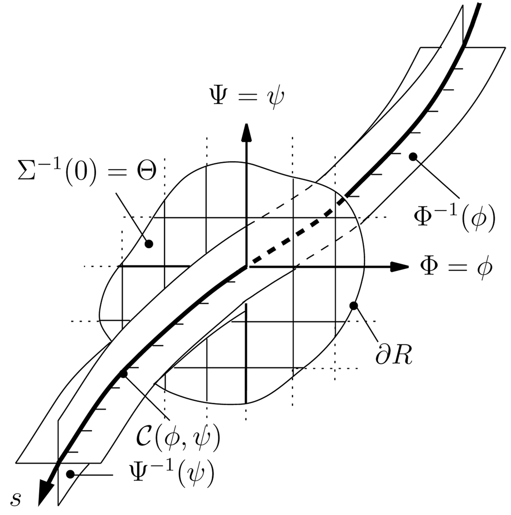
In this paper, curves (fibers) will be represented by the intersection of two level set functions, points on the curve by intersecting with a third level set function. In the context of fiber bundles, this representation induces a coordinate system locally adapted to the fiber bundle geometry.
Given two level set functions Φ(x) : ℝ3↦ ℝ and Ψ(x) : ℝ3 ↦ ℝ, with ‖∇Φ‖ ≠ 0, ‖∇Ψ‖ ≠ 0, a curve 𝒞(φ, ψ) is represented by the intersections of the two level sets
where (φ, ψ) denotes the local coordinates of the curve on a pre-specified two-dimensional origin manifold, Θ, and (·)−1 the set valued inverse. To complete the coordinate representation by parameterizing along a curve, an additional level set function, Σ (Σ(x) = 0 for x ∈ Θ), encodes arclength, s, (‖𝒞s‖ = 1),
See Fig. 1 for an illustration. Sec. 3 describes the construction of the level set functions.
Fig. 1.
Level set representation of a fiber. Example fiber point at coordinates (φ, ψ, 0), the origin manifold and its coordinate system.
2.2 Extracting Measures of Geometry and Diffusion
Define y(x) = (Φ(x), Ψ(x))T and the indicator function
where R is a region of interest within the origin manifold (e.g., an area that encompasses a complete cross section of a fiber bundle, see Fig. 1). The volume and local area of a fiber bundle are then
where Ω is the domain of integration and δ(·) denotes the Dirac delta function.
Mean and variance of a quantity q (e.g., fractional anisotropy) may be defined over the volume
| (1) |
or locally over an arclength isosurface1
| (2) |
These local measurements are useful to investigate changes along the fiber bundle (in the fiber direction).
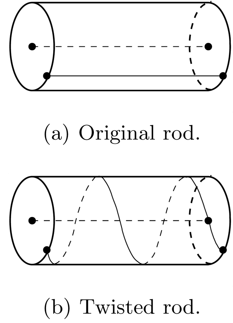
Looking at geometric properties (e.g., curvature, torsion) of an individual fiber can be deceiving. Consider twisting a circular rod as depicted in Fig. 2. Its core does not change during the twisting motion, whereas an initially straight line on the outer surface of the rod will turn into a circular helix with constant, non-vanishing curvature and torsion. Visualizing the levelsets of Φ and Ψ allows to capture such twisting deformations.
Fig. 2.
Local effect of twisting
A mean fiber, 𝒞̄(s), can be defined as the curve that passes through the centers of gravities of the arclength isocontours2, i.e.,
| (3) |
3 Implementation
The level set functions Φ, Ψ, and Σ are computed on a grid (e.g., the voxel grid prescribed by the scanner resolution). Given the velocity field υ induced by the reconstructed diffusion tensor field a fiber tract starting at point (φ, ψ) of the origin manifold traces out the curve given by the solution of the ordinary differential equation 𝒞s(x, s) = υ(x). In contrast to conventional tractography algorithms, in this paper, every point on the fiber tract is associated with an arclength, s, from the origin, as well as the point (φ,ψ), it originated from. Expressed as a partial differential equation on the grid, the level set functions need to fulfill
| (4) |
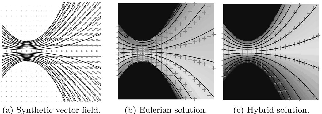
The straightforward (based on standard finite-differences) implementation of the desirable Eulerian solution of Eqs. 4 suffers from undesired boundary effects as shown in Fig. 3(b); boundary data pollutes the constructed level set function. Consequently, the reconstructed fibers (solid lines) do not agree with the ground-truth (crosses) based on the synthetic vector field of Fig. 3(a). Thus, in this paper, Eqs. 4 are solved by explicitly computing fiber tracts and interpolating the associated data at every fiber integration point onto the fixed grid. This hybrid method agrees well with the theoretical fiber tracts of Fig. 3(c) and readily extends existing streamline-based fiber tracing algorithms. A reseeding strategy is employed to cope with diverging fibers. Secs. 3.1 and 3.2 discuss the methods for interpolation, extrapolation, and reseeding.
Fig. 3.
Constructed fiber level set functions
3.1 Interpolation and Extrapolation
Levelset values at grid points need to be interpolated, since streamlines will mostly not pass through them. Streamline integration points are not uniformly distributed in space, yielding a scattered data interpolation problem. Here, natural neighbor interpolation is employed [10]. Given a set of points 𝒮, and its associated Voronoi cells3 𝒱(𝒮), the natural neighbors of a point x are the points whose Voronoi cells, 𝒱p, intersect with the Voronoi cell, 𝒱x, of x based on the point set 𝒮 ∪ x. Interpolation weights, for a measurement quantity q, are computed based on the intersection areas of the Voronoi cells:
If the interpolation point x does not lie within the convex hull formed by the given data points, values are linearly extrapolated to be able to capture the implicit boundary of the fiber bundle.
3.2 Density Measurements and Reseeding
Seeding fiber tracts from a region of interest will lead to a nonuniform coverage of the fiber bundle by fiber tracts, especially in regions where fibers diverge. Adaptively reseeding fibers within voxels of low density (lower than a given threshold) allows for a more uniform sampling of space. Particle density at x¯ is computed by convolution with a smoothing kernel [11], S,
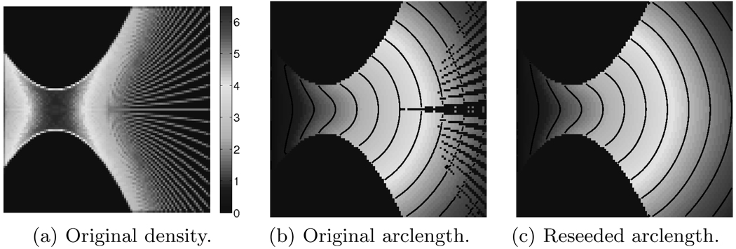
where xi are the known locations of the fiber tract integration points. New fiber tracts are only initialized at locations within the convex hull of already known interpolation points (by means of natural neighbor interpolation) to avoid capturing fibers not consistent with the initial seeding. Fig. 4(a) shows the estimated point density before reseeding. Reseeding yields a more uniform density (and thus tract) distribution. Figs. 4(b) and 4(c) show the arclength field and its isocontours before and after reseeding. Values in regions that were previously not computable are filled in through reseeding4.
Fig. 4.
Reseeding effect of the hybrid bundle tracing scheme
4 Results and Modalities
The algorithm described in Secs. 2 and 3 was applied to extract parts of the cingulum bundle and the corona radiata.
For the cingulum, six diffusion weighted images and one baseline image were acquired on a 1.5 Tesla GE scanner. Scans were performed coronally, with a resolution of 1.7 × 1.7 × 4.0 (mm) and a one mm interslice spacing, using line scan diffusion imaging. For the corona radiata, twenty-five diffusion weighted images and one baseline image were acquired axially, with a resolution of 1.9 × 1.9 × 2.4 (mm), using Echo Planar Imaging on a 3.0 Tesla GE scanner. All images were subsequently upsampled to isotropic voxels.
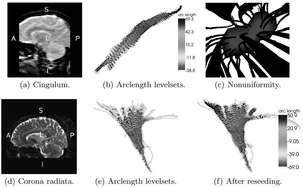
Figs. 5(a) and 5(d) show the boundaries of the traced cingulum bundle and the corona radiata (i.e., the envelopes of χR(y(x))) overlayed on a sagittal brain slice respectively. Fig. 5(e) shows the arclength isosurfaces for the corona radiata. Figs. 5(b) and 5(f) show the respective arclength isosurfaces after reseeding for the cingulum bundle and the corona radiata. Reseeding improved the tracing result. Fig. 5(c) shows a zoom on one of the arclength isosurfaces of the cingulum bundle. It highlights the uneven distribution of streamlines passing through. Statistical quantities based on values computed at the locations of the intersection points of the streamlines with the arclength isosurface can now be replaced by integration over the arclength isosurface itself, removing potential bias towards more densely sampled areas.
Fig. 5.
Experimental results for the cingulum bundle and the corona radiata. (See http://pnl.bwh.harvard.edu/people/marc/miccai2006/ for color figures.)
5 Discussion and Future Work
Moving away from describing a fiber bundle by a finite number of streamlines, this paper introduced an implicit representation of a fiber bundle. The bundle, in this implicit representation, consists of a continuum of fibers. Fiber bundle properties can now be defined as integrals over cross-sectional areas or the bundle volume, instead of relying on the possible nonuniform sampling of a streamline representation. Further, a complete coordinate system has been introduced, warped to the geometry of the traced fiber bundle. We believe this coordinate system may be useful to establish in-between subject correspondences for population studies. Further research will investigate the proposed methodology in the context of multiple subjects and will look at alternative numerical schemes.
Acknowledgements
This work was supported in part by a Department of Veteran Affairs Merit Award (SB,MS,CFW), a Research Enhancement Award Program (MS), and National Institute of Health grants R01 MH50747 (SB,MS), K05 MH070047 (MS), and U54 EB005149 (MN,SB,MS). The authors thank Dr. Gordon Kindlmann for providing the Teem library used in this research (http://teem.sourceforge.net/).
Footnotes
Eq. 1 and Eq. 2 assume a uniform density distribution of fibers. Their integrands may be locally scaled to incorporate geometric stretch and compression effects. See [9] on how to compute this scaling based on the mean curvature of the arclength levelset Σ, which locally quantifies the tendency of fibers to converge or diverge.
A reparameterization is necessary to obtain an arc-length parameterized mean fiber.
The Voronoi cell 𝒱x of a point x ∈ ℝn, with respect to the point set 𝒮 ∪ x, is the n-dimensional polytope containing all the points closest to x.
If the initial seeding is “dense enough”, reseeding may not be necessary.
Contributor Information
Marc Niethammer, Email: marc@bwh.harvard.edu.
Sylvain Bouix, Email: sylvain@bwh.harvard.edu.
Carl-Fredrik Westin, Email: westin@bwh.harvard.edu.
Martha E. Shenton, Email: shenton@bwh.harvard.edu.
References
- 1.Kubicki M, Westin CF, Maier SE, Mamata H, Frumin M, Ernst-Hirshefeld H, Kikinis R, Jolesz FA, McCarley RW, Shenton ME. Diffusion tensor imaging and its application to neuropsychiatric disorders. Harvard Review of Psychiatry. 2002;10:324–336. doi: 10.1080/10673220216231. [DOI] [PMC free article] [PubMed] [Google Scholar]
- 2.Ding Z, Gore J, Anderson A. Classification and quantification of neuronal fiber pathways using diffusion tensor MRI. Magnetic Resonance in Medicine. 2003;49:716–721. doi: 10.1002/mrm.10415. [DOI] [PubMed] [Google Scholar]
- 3.Corouge I, Gouttard S, Gerig G. Towards a shape model of white matter fiber bundles using diffusion tensor MRI; Proceedings of the International Symposium on Biomedical Imaging, IEEE; 2004. pp. 344–347. [Google Scholar]
- 4.Brun A, Knutsson H, Park HJ, Shenton ME, Westin CF. Clustering fiber tracts using normalized cuts. Seventh International Conference on Medical Image Computing and Computer-Assisted Intervention (MICCAI’04); Lecture Notes in Computer Science; Rennes - Saint Malo, France. 2004. pp. 368–375. [DOI] [PMC free article] [PubMed] [Google Scholar]
- 5.Campbell JSW, Siddiqi K, Rymar VV, Sadikot AF, Pikeat GB. Flow-based fiber tracking with diffusion tensor and q-ball data: Validation and comparison to principal diffusion direction techniques. NeuroImage. 2005 doi: 10.1016/j.neuroimage.2005.05.014. in press. [DOI] [PubMed] [Google Scholar]
- 6.Pichon E, Westin CF, Tannenbaum A. A Hamilton-Jacobi-Bellman approach to high angular resolution diffusion tractography. Eighth International Conference on Medical Image Computing and Computer-Assisted Intervention (MICCAI’ 05); Lecture Notes in Computer Science 3749; Palm Springs, CA, USA. 2005. pp. 180–187. [DOI] [PMC free article] [PubMed] [Google Scholar]
- 7.Lenglet C, Deriche R, Faugeras O. Inferring white matter geometry from diffusion tensor MRI: Application to connectivity mapping; Proceedings of the 8th European Conference on Computer Vision; 2004. pp. 127–140. [Google Scholar]
- 8.Osher S, Fedkiw R. Level Set Methods and Dynamic Implicit Surfaces. Springer Verlag: 2003. [Google Scholar]
- 9.Pichon E. PhD thesis. Georgia Institute of Technology; 2005. Novel Methods for Multidimensional Image Segmentation. [Google Scholar]
- 10.Sibson R. A brief description of the natural neighbor interpolant. In: Barnett DV, editor. Interpreting Multiariate Data. 1981. [Google Scholar]
- 11.Monaghan JJ. Smoothed particle hydrodynamics. Reports on Progress in Physics. 2005;68:1703–1759. [Google Scholar]


