

Abstract
Micropatterned poly(dimethylsiloxane) substrates fabricated by soft lithography led to large-scale orientation of myoblasts in culture, thereby controlling the orientation of the myotubes they formed. Fusion occurred on many chemically identical surfaces in which varying structures were arranged in square or hexagonal lattices, but only a subset of patterned surfaces yielded aligned myotubes. Remarkably, on some substrates, large populations of myotubes oriented at a reproducible acute angle to the lattice of patterned features. A simple geometrical model predicts the angle and extent of orientation based on maximizing the contact area between the myoblasts and patterned topographic surfaces. Micropatterned substrates also provided short-range cues that influenced higher-order functions such as the localization of focal adhesions and accumulation of postsynaptic acetylcholine receptors. Our results represent what we believe is a new approach for musculoskeletal tissue engineering, and our model sheds light on mechanisms of myotube alignment in vivo.
Introduction
Mammalian skeletal muscles are composed of oriented multinucleated muscle fibers, each of which arises from the fusion of many mononucleated myoblasts (1,2). Early in development, a set of primary myoblasts fuses to form myotubes. Later, a larger group of secondary myoblasts arises and fuses to form secondary mytotubes. Eventually, all myotubes mature to form muscle fibers (1). The primary myotubes form a scaffold that orients fusion of the secondary myoblasts, but little is known about the cues that direct orientation of the initial set of primary myotubes. Possible cues include structural, chemical, and mechanical factors that affect cell adhesion, motility, orientation, and polarization (3,4).
Here, we focus on the influence of topographical cues on the orientation of myotubes into an organized monolayer. Previous studies have documented the successful alignment of myotubes on substrates containing micron- and nanoscale topography (3,5,6), but none induced alignment over large-scale areas (mm2), and to date, only line-like features have been analyzed in any significant detail (5–12). We therefore reexamined this issue using poly(dimethylsiloxane) (PDMS) substrate (5,13) patterned with symmetric topographic features. We found that all patterns permitted fusion of myoblasts, but only a subset promoted long-range orientation. Unexpectedly, on some substrates, the specific angle of alignment was not obviously related to the orientation of the substrate features. To understand the role of the factors that influence myotube alignment, we explored the range of parameters that lead to ordering, and analyzed the results in terms of a simple geometric model. We show that the same substrate features that lead to global myoblast ordering can also regulate the local aggregation of acetylcholine receptors (AChR) at discrete sites on the myotube membrane. Together, our findings provide what we believe are new insights into the mechanism of myotube alignment, as well as a possible basis for engineering oriented muscles.
Materials and Methods
Fabrication of flat and patterned PDMS molds
We obtained flat surfaces by curing PDMS against a polystyrene petri dish. We fabricated a topographically patterned master by molding PDMS against a photoresist-patterned SiO2/Si(100) substrate fabricated by conventional photolithography and standard procedures of soft lithography (14). Typically, we coated a layer of Shipley 1800 series positive-tone photoresist (Rohm & Haas Electronic Chemicals, Philadelphia, PA) on precleaned silicon wafers (N/phosphorus or P/boron doped, 1–10 Ω-cm; Silicon Sense, Nashua, NH) by spin-coating an adhesion layer of hexamethyldisilazane (Shin-Etsu Chemical, Tokyo, Japan), followed by the photoresist at the same terminal speed. The thickness of the photoresist layer was controlled by the viscosity of the photoresist and the terminal spin speed. After spinning, the wafers were baked on a contact hotplate at 115°C for 5 min, followed by photolithography (AB-M contact aligner, 25 mW/cm2 Hg source) and developed in tetramethyl ammonium hydroxide (0.3 N; Rohm & Haas Electronic Chemicals) for 30–60 s. We generated patterns (masters) in the photoresist using high-resolution transparencies created with CLEWin layout editor (WieWeb Software, Hengelo, The Netherlands) and printed by CadArt (Bend, OR). All photoresist-patterned wafers were coated with a release layer (1H, 1H, 2H, 2H-perfluorooctyltrichlorosilane, 98%; Aldrich, Milwaukee, WI) for 2 h under reduced pressure (500 mTorr) and molded with PDMS (catalyst and prepolymer in 1:10 w/w ratio, Sylgard 184 kit; Dow Corning, Midland, MI). The PDMS mold was cured for 3 h at 70°C in a convection oven. The depth of the photoresist features on the silicon wafer was measured by profilometry (Dektak 6M profilometer; Veeco, Woodbury, NY).
Fabrication of thin PDMS membranes
Immunostaining of myoblast/myotube alignment on the topographically patterned PDMS surface was performed on thin pieces of PDMS. We attached a 1.5 cm × 1.5 cm piece of the silicon single-crystal wafer with photoresist-patterned features to a glass slide in between two pieces of blank silicon wafer covered with a piece of tape. The tape (200 μm thick) served as a spacer and defined the thickness of the PDMS membrane. We coated photoresist-patterned silicon wafer pieces with the release layer and molded the PDMS (catalyst and prepolymer in 1:10 w/w ratio, Sylgard 184 kit; Dow Corning) by placing the glass slide with attached wafer pieces upside down in the PDMS catalyst/prepolymer mixture. After applying reduced pressure to remove trapped air bubbles, we cured the PDMS mold for 3 h at 70°C in a convection oven. We released the fragile PDMS membrane from the surface by submerging the PDMS-coated piece of photoresist-patterned silicon wafer in ethanol. This dissolved the photoresist and released the 200 μm thick PDMS membrane from the surface. Since these membranes are not self-supporting, they were placed in a polystyrene petri dish for storage. One day before culture, the PDMS membranes were placed on a glass slide, soaked in 70% ethanol, and sonicated individually for 30 min. The PDMS membranes were dried in a culture hood for 10 min, exposed to ultraviolet radiation for 30 min, placed in culture petri dishes, and coated with a solution of 10 μg/mL of mouse laminin-111 (Invitrogen, Carlsbad, CA) in Leibovitz-15 (L-15) medium (Invitrogen) supplemented with 0.2% NaHCO3 (Invitrogen) overnight at 37°C. The laminin solution was aspirated immediately before the cells were plated, and membranes were rinsed 9× with culture-grade phosphate-buffered saline (PBS; Invitrogen).
Tissue culture
C2C12 cells were obtained from the American Type Culture Collection and cultured as described previously (15). They were carried on gelatin-coated dishes in growth media consisting of Dulbecco's modified Eagle's medium (DMEM) with high glucose content, supplemented with 100 μg/mL penicillin-streptomycin, L-glutamine (100 μg/mL), and 20% fetal calf serum. After trypsinization (Triple Express; Invitrogen), the myoblasts were transferred to petri dishes containing the PDMS membrane and grown to confluency. The confluent cells were switched to fusion media consisting of DMEM containing 2% horse serum with penicillin-streptomycin and L-glutamine to induce fusion. Cells were incubated at 37°C, 5% CO2 for 3–5 days after fusion.
Immunostaining
Myotubes were fixed in 2% paraformaldehyde in PBS for 10 min, followed by three washes in PBS. Nonspecific staining was blocked by incubating the myotubes in 2% goat serum/2% bovine albumin serum (BSA) and 0.1% Triton X-100 in PBS for 30 min. Cultures were then incubated overnight at 4°C with mouse anti-human talin (C-terminal; Chemicon International), rabbit anti-laminin (clone 23-6/14; Sanes Lab), or fluorescently labeled alpha-Bungarotoxin (BTX; rhodamine or Alexa-488; Invitrogen). Antibody detection was performed using Alexa-488 or Alexa-568 coupled goat secondary antibodies (Invitrogen). After three washes in PBS, the cells were labeled with 4′,6-diamidino-2-phenylindole to visualize the nuclei. Epifluorescence images were obtained on an upright microscope (Zeiss Imager.Z1, Carl Zeiss Inc., Thornwood, NY) equipped with a cooled charge-coupled device camera (AxioCam MRm). We captured the images with Axiovision 4.6 software and assembled the figures using Adobe Illustrator software. Cell measurements, such as determination of myotube angles, were performed using Metamorph 4.0 software. Large field of view images were collected by means of a motorized stage mounted on an upright microscope (Zeiss LSM 5 Pascal) with a dipping cone objective. Images were captured, tiled, and stitched using Axiovision 4.6 software equipped with a Mosaix feature.
Geometric model calculations
The simplified model of the myoblast consisted of a solid sphere representing the nucleus, which was flanked by two equivalent square pyramidal wedges that constituted the cytoplasm of the myoblast. The top-down projection is assumed to be a modified diamond with dimensions based on the size of the nucleus and the total volume of individual myoblasts measured experimentally. We calculated the contact area between the model myoblast and topographically patterned surface by incrementing the angle of the myoblast relative to some initial placement with respect to the topography. In the case of the square arrays, we placed the myoblast across a row of the posts (defined as an angle of 0°) and rotated the myoblast clockwise around its center by increments of 5°. In the case of the diamond-patterned substrate, we initially placed the left side of the long axis of the myoblast parallel and flush to the centerline running through the long axis of the 60 μm diamond. This is considered the initial condition (denoted as 0°), and the myoblast was rotated clockwise around the lower left-hand corner of the model myoblast in increments of 1°. The contact area between the myoblast and topographically patterned surface was analyzed with the use of the CLEWin layout editor.
Laplace-Buffon calculations
To establish whether the distribution of AChRs was random with respect to substrate features, we calculated the average perimeter of an ellipsoid aneural AChR and the probability for it to cross the border from the floor to the features, as predicted by the modified Laplace-Buffon noodle equation (16)
In this equation, x is the perimeter of the stereotypical cluster, and L is the gap between the features. The 1/4 multiplication reflects the fact that each time the cluster perimeter crosses a border, it equals one cross for a solid cluster (hence the first factor of 1/2). Then, since our stamps do not represent perfect checkerboard patterns, we had to modify the calculated value based on the total number of borders a cluster can cross: 1/2 of what would be seen on the Laplace-Buffon pattern, together totalling 1/4.
Results and Discussion
Myoblast growth and fusion on flat and patterned substrates
To investigate the response of skeletal muscle cells to substrate topography, we cultured cells of the C2C12 myogenic cell line on thin-film (100–200 μm thick) PDMS membranes. C2C12 myoblasts are a subclone of the C2 cell line (17,18), which was established from normal adult mouse leg muscle. C2C12 cell grow as myoblasts but can be induced to fuse into multinucleated myotubes by lowering the level of serum in the culture media. They are used extensively to study myogenesis and postsynaptic differentiation in vitro (15,19). We compared the behavior of C2C12 cells on three PDMS substrates uniformly coated with laminin: 1), flat surfaces; 2), lines of 20 μm width separated by 20 μm gaps; and 3), square posts of 20 μm edge length separated by 20 μm lanes. As shown in Fig. 1, the myoblasts divided, fused, and formed myotubes to a similar extent on all three substrates, but the shape and alignment of the myotubes differed among them in four respects. First, myotubes were randomly oriented on flat substrates (Fig. 1 a) but aligned on both patterned substrates (Fig. 1, b and c, and Fig. S1 a in the Supporting Material). Second, myotubes were more variable in diameter and shape on flat surfaces than on patterned substrates (Fig. 1 d). Third, branching was less frequent on patterned than on flat surfaces (Fig. 1 e). Fourth, and most surprisingly, the angle of alignment of the myotubes with respect to the substrate features differed between lines and posts. On parallel grooves, myotubes aligned along the length of the grooves (Fig. 1 b), as previously reported on similar patterns (7,9,11,12). In contrast, the substrate patterned with posts gave rise to an unexpected alignment of myotubes with a mean angle of 25° ± 5° relative to the horizontal axis of symmetry of the lattice (Fig. 1, c and f).
Figure 1.
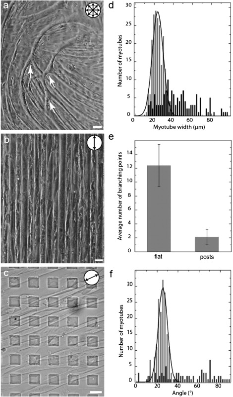
Alignment of myotubes on patterned surfaces. (a–c) Differential interference contrast (DIC) microscopy images of C2C12 myotubes grown on laminin-coated PDMS substrates. (a) Myotubes are unaligned on flat surfaces. Arrows indicate branching points. (b) Myotubes on patterned lines (20 μm width separated by 20 μm gaps). (c) Myotubes on square posts (20 μm edge length separated by 20 μm gaps) arranged in a square lattice. (d) Width of myotubes grown on flat (black) or square post-patterned surfaces (gray). On the patterned surface, the myotubes display a uniform diameter with a single Gaussian peak; on the flat substrate, the distribution of the width of the myotubes is broader and flat. (e) The average number of branching points is much lower on patterned posts than on flat surfaces. (f) Relative angle of myotubes grown on flat (black; using an arbitrary horizontal) and post-patterned surfaces (gray; angle relative to a row of horizontal topographic features) PDMS substrates. Myotubes grown on the square post-patterned substrate histogram align at ∼25° (gray). The distribution is a single Gaussian fit. Circular pictograms indicate the alignment orientation of the myotubes. Scale bars = 20 μm.
In light of the influence of the substrate on myotube alignment, we generated and assayed substrates with a wide range of topography, including variations in spacing, height, arrangements (such as square and hexagonal lattices), and feature shape (lines, square, circular, and diamond posts; Table S1, a and b). Although our measure of alignment is based on observations of myotubes, our interpretation is based on the fact that motile myoblasts are initially involved in alignment. We argue below that geometric constraints associated with their roughly elliptic shape (50–60 μm × 10–15 μm) and relatively inelastic nuclei (∼10 μm diameter) play crucial roles in the alignment process.
Influence of spacing and height on cellular alignment
We compared fixed 20 μm edge-length square posts arranged in a square lattice with variable height (h) or gap (g) between posts. We found that both the height of the posts and the width of the gap affected myotube alignment. Fig. 2 a shows the range of heights and gaps that supported large-scale alignment of myotubes. In the range g ∈[5, 20] μm, only g = 20 μm induced large-scale alignment. This is consistent with the idea that when the posts are too far apart, the surface appears featureless to the myoblasts. Likewise, when the posts are very close (≤10 μm), the surface (the tops of the posts) appear as a featureless flat substrate, and the myoblasts cannot fit in the grooves due to the steric limitations imposed by their stiff nuclei. Thus, on surface patterns of g ≥ 30 μm, alignment is lost over large areas.
Figure 2.
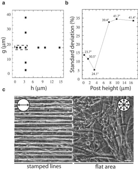
Influence of height (h) and gap (g) of square (20 μm edge length) posts on myotube alignment. (a) The g-h combination in which alignment was observed is outlined. (b) SD for alignment angle of myotube monolayers grown on square post-patterned substrates as a function of height (n ≥ 75 per square post height surface). The average angle is included with each data point. An average angle does not necessarily imply strong alignment. (c) DIC image of an abrupt line-to-flat transition stamp (parallel 20 μm wide lines, separated by 20 μm and 3.5 μm tall) demonstrates the necessity for the continuous presence of the appropriate topography to sustain alignment. Circular pictograms in c indicate the alignment orientation of the myotubes over the corresponding areas. Scale bar = 20 μm.
The height (h) of the posts can also affect the uniformity of myotube alignment. Indeed, a previous study showed that tall posts limit cell-cell contact, which is required for proper fusion of myoblasts into myotubes (8). To address this issue systematically, we assessed myotube alignment, width, and branching on posts 0.6–14.7 μm tall (Fig. 2 b and Fig. S1, b and c). On patterns of 20 μm edge length separated by 20 μm square posts, we observed that the lowest standard deviation (SD = 5°) of the average angle was obtained for the 3.5 μm tall posts. The number of branching points and the variation in myotube width were also lowest at this height, suggesting that features within this range are best suited for large-scale alignment of myotube monolayers. The average angle varied with the height of the post, and for posts > 3.5 μm tall, orientation was lost. Together, these observations demonstrate that spacing and height both influence alignment, and provide the greatest uniformity on featured stamps with h = 3.5 μm and g = 20 μm.
Local requirement for patterned substrates to align muscle cells
We next investigated whether patterned features are needed throughout the substrate to maintain long-range muscle cell alignment, or whether orientation can be carried over onto flat surfaces once it is successfully established in a patterned area. To address this question, we cultured C2C12 cells on PDMS membranes containing a region at which an aligning stamp (lines; see Fig. 1 b) was juxtaposed to a flat surface. As shown in Fig. 2 c, alignment of the myotube monolayer was lost within ≤100 μm of the interface between aligning (left) and nonaligning (right) substrate, corresponding to 1–2 myoblast lengths. This is consistent with the notion that short-range interactions of substrate features with the myoblasts lead to myotube alignment. A similar result was observed on a stamp containing an abrupt interface between an aligning square lattice and a nonaligning hexagonal lattice of posts (data not shown). Hence, large-scale myotube monolayer alignment requires a patterned topography over the entire surface.
Influence of feature shape on cellular alignment
To test whether the shape of the substrate features affected myotube alignment, we compared alignment on PDMS-patterned stamps bearing square or circular posts. In both cases, the posts were 20 μm in length/diameter, 3.5 μm tall, separated by a gap of 20 μm, and arranged in a square lattice. Myoblasts aligned on substrates with square posts (Fig. 3 a), but not on those with circular posts (Fig. 3 b). The only physical difference between the two lattices is that one offers four flat right-angled walls, whereas the other is a continuous curved wall, suggesting that feature shape influences alignment.
Figure 3.
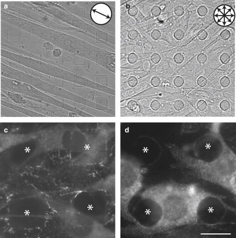
(a and b) DIC images of myotubes grown on (a) square post-patterned (20 μm edge length separated by 20 μm; 3.5 μm tall) and (b) circular post-patterned (20 μm diameter circles separated by 20 μm; 3.5 μm tall) substrates. (c and d) Anti-talin immunofluorescence marking focal adhesions. Bright, rod-like talin-rich focal adhesions outline the edges and corners of the square posts (c). A more even pattern of talin is present on circular posts (d). Asterisks in c and d mark the locations of posts. All scale bars = 20 μm.
One possible explanation for the different alignment response is that myoblasts may differ in their ability to establish focal adhesions on features with straight or curved walls. Focal adhesions connect the extracellular matrix to the cytoskeleton and mediate transduction of extracellular mechanical cues into cellular responses (20). To address this possibility, we immunostained myoblast cultures using an antibody to talin, a cytoskeletal component of focal adhesions (21). Talin-rich puncta localized differently to the sides of square and circular posts. On square posts, localization of puncta was more abundant on the walls of the square posts than on the corners; the immunostaining was bright and adopted a rod-like pattern that seemed to radiate from the sides of the features (Fig. 3 c). In contrast, on circular posts, anti-talin-immunostained puncta were smaller and more uniformly distributed along the side of the posts (Fig. 3 d).
Focal adhesions on square posts may act as anchoring points for the cytoskeleton. On circular posts, myoblasts appeared to wrap around the features in a cup-like fashion, as if attempting to internalize them. Consistent with this observation, recent studies on target geometry in alveolar macrophages phagocytosis behavior reported that particle shape and size influence cell behavior (22,23). In particular, if the encounter between the cell and particle occurred at a location with a large solid angle, the cell was unable to internalize the particle. Thus, for topographic features with the same height, lattice symmetry, and spacing, feature shape may determine the type of focal adhesion that orchestrates movements and alignment of myoblasts, thereby influencing the alignment of myotubes.
A geometrical model of a myoblast explains the angle of alignment
We were surprised that alignment of myotubes on some substrates was not parallel to rows of features (Fig. 1 c). Myotubes grown on post-patterned surfaces of 0.6 μm, 1.7 μm, and 3.5 μm tall features had an angle of ∼25° relative to the horizontal axis of symmetry of the lattice, and myotubes on 0.6 μm parallel lines had an angle of ∼10° relative to the axis of symmetry (Fig. 1 c and data not shown). To understand this relationship, we hypothesized that in addition to achieving confluence, myoblasts maximize adhesive contact with the underlying substrate. A simple geometric model based on this idea allows prediction of the preferred angle of alignment in myoblasts on patterned surfaces.
Our model is based on three assumptions, all of which are consistent with prior measurements: 1), that the myoblast nucleus is much stiffer than the rest of the cell (24); 2), that the myoblast volume remains constant during the course of an experiment; and 3), that at high confluence, myoblasts adopt a strongly elongated shape. This shape is induced by the increasing number of cells on a surface and the natural behavior of the cells to pack and fuse in an end-to-end fashion. The elongated shape they adopt maximizes tail-to-tail contact as they prepare to fuse into myotubes (see Fig. S3, f–j, for the influence of confluency on cell shape and aspect [x, y] ratio).
We determined the parameters needed to fit the model experimentally. The average nuclear diameter is 11 ± 2 μm (n = 200 myoblasts), amounting to a total incompressible volume of ∼700 μm3 (see Fig. S3, a–c). We measured the volume of trypsinized myoblasts in culture, and the average volume was ∼2800 ± 10 μm3 (n = 200). We obtained the surface area (footprint) occupied by the ventral portion of the myoblast by measuring the axes of >200 cells at high confluence in the x- and y-dimensions; the footprint was ∼400 ± 20 μm2. For comparison, if the myoblast spread like an egg-drop with a uniform cytoskeleton thickness of 1 μm, the footprint covered would be ∼2000 ± 26 μm2. Myoblast thickness was assessed by atomic force microscopy (AFM). AFM linescans obtained in this way demonstrate that the thickness of the cytoplasm of a single myoblast can vary over the range of 0.5–10 μm (see AFM data in Fig. S3, d and e). Thus, myoblasts do not spread over the surface isotropically like an egg-drop to maximize contact with the substrate.
Based on these observations, we modeled the myoblast as a sphere flanked on both sides by a square pyramidal wedge whose square base dimension (11 μm × 11 μm) is determined by the diameter of the nucleus. From AFM linescan measurements, we set the thickness of the edge of the square pyramid to 1 μm (Fig. 4 a). The largest footprint that the model myoblast could cover on a flat substrate subject to these constraints would be ∼400 μm2, which is identical to our experimental value, and corresponds to the measured cell length of 58 ± 1 μm under conditions of high confluence.
Figure 4.
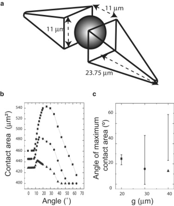
Model for myotube alignment on patterned substrates. (a) Two identical square pyramidal wedges flanking a nucleus represent a model of myoblast. The extremities of the wedges are set to a thickness of 1 μm. Values are justified in Fig. S4. (b) Determination of the maximum contact area as a function of the angle relative to the horizontal axis of symmetry for a single myoblast. The ventral footprint (in contact with a flat substrate) occupies an area of 400 μm2. As a single myotube is rotated around its center, the contact area increases until a maximum contact area is reached at an angle of ∼25° for the 20 μm edge length square post-patterned substrates (g = 20 μm separation; squares). As the separation increases to 30 μm (circles) and 40 μm (triangles), the maximum contact area occurs at smaller angles. The model predicts a maximum contact area for the 30 μm and 40 μm separation, but no alignment is observed experimentally. (c) Predicted values for angle of maximum contact area for the three lattices in b. The 20 μm, 30 μm, and 40 μm separation square post lattices are represented by squares, triangles, and circles, respectively. The error bars in c correspond to the experimental values (± SD) measured for myotubes grown on these lattices.
Next, we calculated the angle at which a model myoblast maximized its footprint with the substrate topography by using the floor of the stamp, the side walls, and the top surface of the features in comparison with the initial calculated footprint on a flat surface. We reasoned that the maximum footprint value obtained by additional contact onto the side walls (z-dimension) would correspond to the experimentally observed angle if the myoblast attempted to maximize its interfacial contact with the substrate. Indeed, time-lapse imaging of myoblasts as they align and fuse reveals that initially small regions of highly aligned myoblasts grow radially until they meet each other, at which sites we observe “grain boundaries” much like those observed in the growth of thin films (data not shown).
For 3.5 μm tall square posts of 20 μm edge length separated by 20 μm, a maximal footprint increase of ∼30% in contact area was observed at an angle of ∼25° (Fig. 4, b and c, solid squares). The calculated angle is in good agreement with the experimentally measured myotube angle of 25° ± 5° (Fig. 4 c), suggesting that the myoblast indeed used the walls of the features (z-dimension) to increase its footprint. As the gap between features increased to ≥30 μm, the maximum contact area increased relative to the footprint on a flat surface, and at large angles (>50°) the footprint area was the same as the flat surface because the myotube was no longer in contact with the walls of the raised square features. The model predicted that myotube alignment would occur at lower angles than were experimentally determined (if observed at all). Myotubes cultured on the PDMS surface patterned with square posts separated by 40 μm were unaligned and looked very similar to those cultured on a flat surface (Fig. 1 a).
As an additional test, we used our model to predict the angle at which myoblasts, and ultimately myotubes, would fuse on more complex substrates. We chose a substrate consisting of diamonds (60 μm major-axis length) arranged in a square lattice with 20 μm gaps between the diamonds. The model predicts an alignment angle of −5°, which is in agreement with the angle (−3° ± 1°) determined from experimental measurements of the alignment of myotubes on the same substrate (Fig. S4, a and b). Moreover, the asymmetry introduced by elongated diamonds forced the alignment of the myotubes in a single direction, along the major axis length. A similar agreement between predicted (−2°) and observed (−3° ± 1°) angles of alignment were obtained on a different substrate composed of diamonds with 40 μm major-axis length arranged in a square lattice with a 20 μm gap between features. Moreover, primary myoblasts behaved similarly on patterned surfaces, suggesting that the alignment due to patterned surfaces is not restricted to particular cell lines (see Fig. S4 c).
Of interest, in previous studies of phagocytes, a model based on the maximization of contact between cell and substrate was previously proposed to explain the unique size-dependent behavior of alveolar macrophages discussed above (22,23). Taken together with the findings of those studies, our results suggest that maximization of contact may be a generally useful concept for modeling cell behavior in multiple contexts.
Influence of topography on the localization of AChRs
In engineered tissues, just as in developing organisms, it is important to control both the alignment of muscle fibers within artificial tissue scaffolds, and the sites at which these fibers are innervated by neurons. Most mammalian skeletal muscle fibers bear a single neuromuscular junction, and most of the junctions are near the midpoint of the muscle fiber, forming a central “end-plate band” in the muscle. Embryonic muscles bear a “prepattern” of postsynaptic specializations that contribute to the pattern of innervation when axons arrive (25), and new neuromuscular junctions form preferentially at preexisting postsynaptic sites when axons regenerate after injury (26). With these considerations in mind, we asked whether patterned substrates that influence myotube alignment could also affect the localization of postsynaptic specializations. We stained cultures with rhodamine-conjugated α-bungarotoxin, which binds tightly and specifically to AChRs that comprise the cardinal feature of the postsynaptic membrane. AChRs form complex, branched aggregates spontaneously on the ventral side of myotubes that contact laminin-coated substrates, but to date there has been no evidence for a nonrandom distribution of these aggregates within regions of contact (15,19).
On flat laminin-coated PDMS surfaces, AChR clusters appeared to form randomly on the ventral side of the myotubes and proceeded to mature into complex structures, as seen previously for laminin-coated glass or plastic (15). In contrast, on square post-patterned substrates (3.5 μm tall, 20 μm edge length separated by 20 μm), AChR clusters formed preferentially in the area between the posts even when the myotubes themselves grew over the posts (Fig. 5, a–c). Immunostaining revealed that laminin was distributed evenly on and between features (Fig. S5), ruling out the possibility that the location of AChR clusters resulted from the differential distribution of laminin across the surface of the PDMS membrane.
Figure 5.
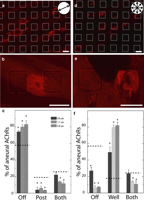
Preferred localization of AChR clusters on patterned surfaces. (a, b, d, and e) Myotubes grown on substrates patterned with square posts (a and b) or wells (d and e), 20 μm edge length separated by 20 μm; 3.5 μm tall or deep. Myotubes were labeled with rhodamine-conjugated α-BTX (red) to label aneural AChR clusters. Myotubes align on the posts, but not in the wells. (a and d) The features are outlined with white dashed lines. (b and d) An AChR clusters shown at high power. (c and f) Histograms of the location of AChR clusters as a function of the height of the posts (c) or depth of the wells (b). Observed values are significantly different than those expected for a random distribution as predicted by the Laplace extension of the Buffon noodle problem (dotted lines). AChR clusters tend to avoid posts but fall within the wells. Scale bars = 20 μm.
To quantify the bias in the distribution, we calculated the probability for a cluster to randomly fall on the floor of the stamp, on a feature, or on a border as predicted by the Laplace-Buffon noodle equation (16). The average perimeter of an ellipsoid aneural AChR cluster was equal to 60 ± 4 μm with a short axis of 12 ± 4 μm and a long axis of 24 ± 6 μm (n = 60 clusters). For clusters of this size, the probabilities of crossing a feature border, being confined to a post or being confined to a lane, are 25%, 18.75%, and 56.25%, respectively. Measured values for localization of clusters off of the posts were significantly different from the random distribution (Student's t-test; p < 0.0001, p < 0.002, p < 0.0044 for 0.6, 1.7, and 3.5 μm posts; n = 4 experiments).
AChR clusters may avoid posts because of their height (they protrude into the cell) or their size (they are smaller than the average cluster diameter). To distinguish between these two possibilities, we tested a substrate in which we substituted posts with wells (3.5 μm depth, 20 μm edge length separated by 20 μm). On this substrate, clusters formed preferentially inside the wells (Fig. 5, d–f). The frequency of appearance of these clusters inside the wells significantly exceeds the random probability calculated by the Laplace-Buffon equation (Student's t-test; p < 0.0002, p < 0.0002, p < 0.0001, for 0.6, 1.7, and 3.5 μm deep wells, respectively; n = 4). This observation suggests that aneural AChR clusters do not avoid regions of limited areas (20 μm × 20 μm), such as the surface of the posts or the bottom of the wells, but they do preferentially avoid regions of protuberances into the cell. Of interest, at the neuromuscular junction in vivo, receptor clusters in the postsynaptic membrane are preferentially associated with the membrane at the crests of junctional folds and are present at low density within the folds, which protrude into the cell (26).
Conclusions
We have analyzed the role of topographical features in the large-scale alignment of myoblasts that eventually leads to myotube alignment. Our experiments are consistent with simple geometric ideas that qualitatively explain how myotube orientation arises in vitro. Furthermore, the patterns we used can bias sites of postsynaptic differentiation.
Our studies raise a question as to what biological patterns myoblasts encounter during myogenesis in vivo. Although the orientation of the secondary myoblasts, and thus the secondary myotubes, is determined by the early arising primary myotubes (see Introduction), it is less clear what cues induce alignment in the primary myoblasts. One candidate is collagen type I, a major component of the extracellular matrix that surrounds developing myoblasts (27). Collagen type I fibers have a distinct topography with constant periodicity resulting in the precise staggering of rod-like collagen molecules (28). The textured surface they create may in turn be used to increase surface adhesion and organize myoblast fusion. Myoblasts in vitro display a preference in binding to fibrous as opposed to soluble collagen type I, and interactions between the two have been reported to occur via talin-containing focal adhesion (29), which in turn can influence cell morphology and behavior.
On a practical level, our study offers an avenue to induce large-scale alignment for musculoskeletal tissue engineering, a well as the possibility to control synapse formation in regenerating muscle and thus increase restoration of function within grafted muscle.
Supporting Material
A table and five figures are available at http://www.biophysj.org/biophysj/supplemental/S0006-3495(09)01426-X.
Supporting Material
Acknowledgments
This work was performed in part at the Center for Nanoscale Systems, a member of the National Nanotechnology Infrastructure Network, which is supported by the National Science Foundation under award No. ECS-0335765. The Center for Nanoscale Systems is part of the Faculty of Arts and Sciences at Harvard University.
This work was funded by grants from the National Institutes of Health to J.R.S. J.G. received a postdoctoral fellowship from the Fond de Recherche en Santé du Québec. R.M.R. received a postdoctoral fellowship (1 F32 NS60356-01) from the National Institutes of Health.
References
- 1.Wigmore P.M., Dunglison G.F. The generation of fiber diversity during myogenesis. Int. J. Dev. Biol. 1998;42:117–125. [PubMed] [Google Scholar]
- 2.Jansen K.M., Pavlath G.K. Molecular control of mammalian myoblast fusion. Methods Mol. Biol. 2008;475:115–133. doi: 10.1007/978-1-59745-250-2_7. [DOI] [PubMed] [Google Scholar]
- 3.Lim J.Y., Donahue H.J. Cell sensing and response to micro- and nanostructured surfaces produced by chemical and topographic patterning. Tissue Eng. 2007;13:1879–1891. doi: 10.1089/ten.2006.0154. [DOI] [PubMed] [Google Scholar]
- 4.Gros J., Serralbo O., Marcelle C. WNT11 acts as a directional cue to organize the elongation of early muscle fibres. Nature. 2009;457:589–593. doi: 10.1038/nature07564. [DOI] [PubMed] [Google Scholar]
- 5.Huang N.F., Patel S., Thakar R.G., Wu J., Hsiao B.S. Myotube assembly on nanofibrous and micropatterned polymers. Nano Lett. 2006;6:537–542. doi: 10.1021/nl060060o. [DOI] [PubMed] [Google Scholar]
- 6.Choi J.S., Lee S.J., Christ G.J., Atala A., Yoo J.J. The influence of electrospun aligned poly(epsilon-caprolactone)/collagen nanofiber meshes on the formation of self-aligned skeletal muscle myotubes. Biomaterials. 2008;29:2899–2906. doi: 10.1016/j.biomaterials.2008.03.031. [DOI] [PubMed] [Google Scholar]
- 7.Charest J.L., Garcia A.J., King W.P. Myoblast alignment and differentiation on cell culture substrates with microscale topography and model chemistries. Biomaterials. 2007;28:2202–2210. doi: 10.1016/j.biomaterials.2007.01.020. [DOI] [PubMed] [Google Scholar]
- 8.Clark P., Dunn G.A., Knibbs A., Peckham M. Alignment of myoblasts on ultrafine gratings inhibits fusion in vitro. Int. J. Biochem. Cell Biol. 2002;34:816–825. doi: 10.1016/s1357-2725(01)00180-7. [DOI] [PubMed] [Google Scholar]
- 9.Lam M.T., Sim S., Zhu X., Takayama S. The effect of continuous wavy micropatterns on silicone substrates on the alignment of skeletal muscle myoblasts and myotubes. Biomaterials. 2006;27:4340–4347. doi: 10.1016/j.biomaterials.2006.04.012. [DOI] [PubMed] [Google Scholar]
- 10.Riboldi S.A., Sadr N., Pigini L., Neuenschwander P., Simonet M. Skeletal myogenesis on highly orientated microfibrous polyesterurethane scaffolds. J. Biomed. Mater. Res. A. 2008;84:1094–1101. doi: 10.1002/jbm.a.31534. [DOI] [PubMed] [Google Scholar]
- 11.Yamamoto D.L., Csikasz R.I., Li Y., Sharma G., Hjort K. Myotube formation on micro-patterned glass: intracellular organization and protein distribution in C2C12 skeletal muscle cells. J. Histochem. Cytochem. 2008;56:881–892. doi: 10.1369/jhc.2008.951228. [DOI] [PMC free article] [PubMed] [Google Scholar]
- 12.Zhao Y., Zeng H., Nam J., Agarwal S. Fabrication of skeletal muscle constructs by topographic activation of cell alignment. Biotechnol. Bioeng. 2009;102:624–631. doi: 10.1002/bit.22080. [DOI] [PMC free article] [PubMed] [Google Scholar]
- 13.Kane R.S., Takayama S., Ostuni E., Ingber D.E., Whitesides G.M. Patterning proteins and cells using soft lithography. Biomaterials. 1999;20:2363–2376. doi: 10.1016/s0142-9612(99)00165-9. [DOI] [PubMed] [Google Scholar]
- 14.Xia Y., Rogers J.A., Paul K.E., Whitesides G.M. Unconventional methods for fabricating and patterning nanostructures. Chem. Rev. 1999;99:1823–1848. doi: 10.1021/cr980002q. [DOI] [PubMed] [Google Scholar]
- 15.Kummer T.T., Misgeld T., Lichtman J.W., Sanes J.R. Nerve-independent formation of a topologically complex postsynaptic apparatus. J. Cell Biol. 2004;164:1077–1087. doi: 10.1083/jcb.200401115. [DOI] [PMC free article] [PubMed] [Google Scholar]
- 16.Arnow B.J. On Laplace's extension of the Buffon needle problem. Coll. Math. J. 1994;25:40–43. [Google Scholar]
- 17.Blau H.M., Pavlath G.K., Hardeman E.C., Chiu C.P., Silberstein L. Plasticity of the differentiated state. Science. 1985;230:758–766. doi: 10.1126/science.2414846. [DOI] [PubMed] [Google Scholar]
- 18.Yaffe D., Saxel O. Serial passaging and differentiation of myogenic cells isolated from dystrophic mouse muscle. Nature. 1977;270:725–727. doi: 10.1038/270725a0. [DOI] [PubMed] [Google Scholar]
- 19.Nishimune H., Valdez G., Jarad G., Moulson C.L., Muller U. Laminins promote postsynaptic maturation by an autocrine mechanism at the neuromuscular junction. J. Cell Biol. 2008;182:1201–1215. doi: 10.1083/jcb.200805095. [DOI] [PMC free article] [PubMed] [Google Scholar]
- 20.Chen C.S., Tan J., Tien J. Mechanotransduction at cell-matrix and cell-cell contacts. Annu. Rev. Biomed. Eng. 2004;6:275–302. doi: 10.1146/annurev.bioeng.6.040803.140040. [DOI] [PubMed] [Google Scholar]
- 21.Morgan J.R., Werner H., Shchedrina V.A., Pypaert M., Pieribone V.A. A role for talin in presynaptic function. J. Cell Biol. 2004;167:43–50. doi: 10.1083/jcb.200406020. [DOI] [PMC free article] [PubMed] [Google Scholar]
- 22.Champion J.A., Mitragotri S. Role of target geometry in phagocytosis. Proc. Natl. Acad. Sci. USA. 2006;103:4930–4934. doi: 10.1073/pnas.0600997103. [DOI] [PMC free article] [PubMed] [Google Scholar]
- 23.Champion J.A., Walker A., Mitragotri S. Role of particle size in phagocytosis of polymeric microspheres. Pharm. Res. 2008;25:1815–1821. doi: 10.1007/s11095-008-9562-y. [DOI] [PMC free article] [PubMed] [Google Scholar]
- 24.Dahl K.N., Ribeiro A.J., Lammerding J. Nuclear shape, mechanics, and mechanotransduction. Circ. Res. 2008;102:1307–1318. doi: 10.1161/CIRCRESAHA.108.173989. [DOI] [PMC free article] [PubMed] [Google Scholar]
- 25.Kummer T.T., Misgeld T., Sanes J.R. Assembly of the postsynaptic membrane at the neuromuscular junction: paradigm lost. Curr. Opin. Neurobiol. 2006;16:74–82. doi: 10.1016/j.conb.2005.12.003. [DOI] [PubMed] [Google Scholar]
- 26.Sanes J.R., Lichtman J.W. Development of the vertebrate neuromuscular junction. Annu. Rev. Neurosci. 1999;22:389–442. doi: 10.1146/annurev.neuro.22.1.389. [DOI] [PubMed] [Google Scholar]
- 27.Lawson M.A., Purslow P.P. Differentiation of myoblasts in serum-free media: effects of modified media are cell line-specific. Cells Tissues Organs. 2000;167:130–137. doi: 10.1159/000016776. [DOI] [PubMed] [Google Scholar]
- 28.Linsenmayer T.F. Collagen. In: Hay E.D., editor. Cell Biology of Extracellular Matrix. Plenum; New York: 1992. pp. 5–37. [Google Scholar]
- 29.Arnesen S., Mosler S., Larsen N., Gadegaard N., Purslow P. The effects of collagen type I topography on myoblasts in vitro. Connect. Tissue Res. 2004;45:238–247. doi: 10.1080/03008200490888424. [DOI] [PubMed] [Google Scholar]
Associated Data
This section collects any data citations, data availability statements, or supplementary materials included in this article.