Abstract
A lens system consisting of two electrostatic quadrupole triplets has been designed and constructed at the Radiological Research Accelerator Facility (RARAF) of Columbia University. The lens system has been used to focus 6-MeV 4He ions to a beam spot in air with a diameter of 0.8 µm. The quadrupole electrodes can withstand voltages high enough to focus 4He ions up to 10 MeV and protons up to 5 MeV. The quadrupole triplet design is novel in that alignment is made through precise construction and the relative strengths of the quadrupoles are accomplished by the lengths of the elements, so that the magnitudes of the voltages required for focusing are nearly identical. The insulating sections between electrodes have had ion implantation to improve the voltage stability of the lens. The lens design employs Russian symmetry for the quadrupole elements.
Keywords: microbeam, quadrupole, electrostatic, sub-micron, charged particle beam
Introduction
For more than 15 years the Radiological Research Accelerator Facility (RARAF) of Columbia University has had a charged particle microbeam facility capable of irradiating the nuclei of individual biological cells with as few as one helium ion or proton [1–2]. Initially, like the first microbeam by Zirkle and Bloom [3], the beam was defined by a collimation system. The collimator consisted of two stainless steel apertures 12.5 µm thick: a 5 µm diameter aperture and a 6 µm diameter anti-scatter aperture, separated by 300 µm [2]. The collimator produced a beam of 6-MeV 4He ions with a diameter of about 6 µm at the cells. Monte Carlo calculations indicated that about 7% of the particles scattered in the first aperture would pass through the second aperture, producing a halo about 8 µm in diameter. In addition, about 2% of the particles were scattered on the radial surface of the second aperture at large angles and consequently entered the cells at distances greater than 4 µm from the center of the beam.
We had essentially reached the lower limit of the size of the beam that can be produced by collimation due to increased scattering as the diameter of the collimators is reduced. In order to make the diameter of the beam smaller and eliminate the halo caused by scattered ions, we decided to develop a focused beam. There were many microprobes in use, mostly using magnetic quadrupoles for focusing [4,5]. Most microprobes for physics applications use a single standard beam in each laboratory; however we need to change easily among different beam particles and energies. We chose to use an electrostatic system of our own design [6] because of two specific advantages:
Electrostatic lenses do not have the hysteresis inherent in magnetic lenses, allowing easy tuning and change between beams of differing ions and energies.
The field strength required for focusing the beam onto the target is independent of ion mass and charge for a given accelerating potential, thus making them ideally suited for heavy-ion beams from electrostatic accelerators.
Description
Design
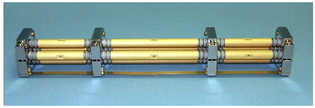
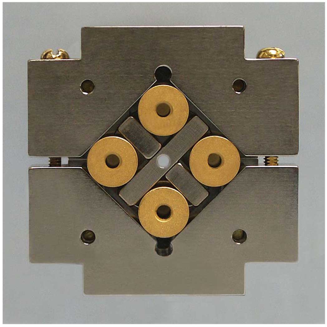
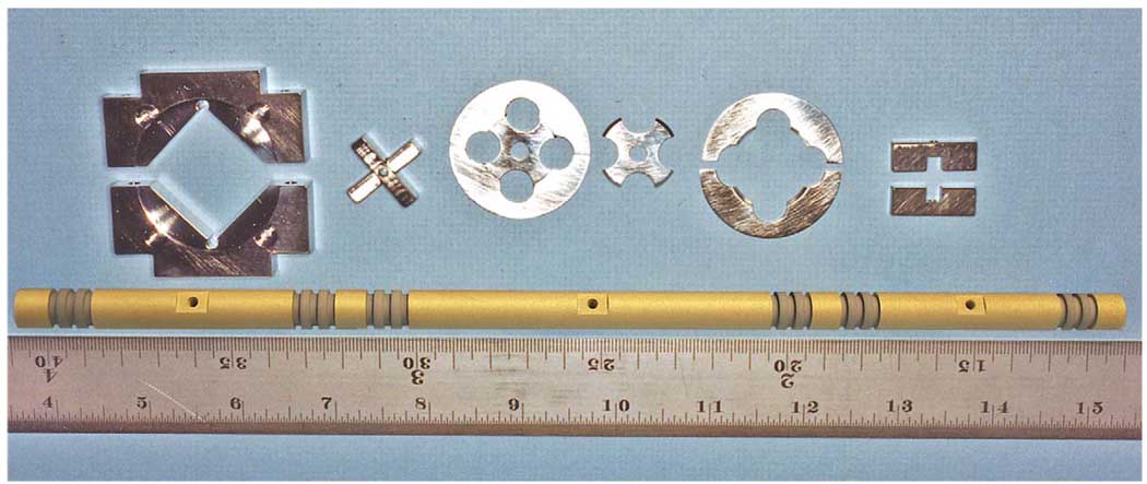
The design of our electrostatic quadrupole triplet (Fig. 1, Fig. 2, Fig. 3) has a number of novel features.
Fig. 1.
Photograph of one of the 300-mm long electrostatic quadrupole triplet lenses. The smooth areas are the electrodes; the grooved areas are insulating sections; the clamps are ground planes. The hole near the center of each electrode is for attachment of the voltage supply. A ground strap (seen at the bottom) connects all the ground planes.
Fig. 2.
Photograph of the end of one of the quadrupole triplet lenses. The cross spacer is seen between the lens rods; the V-blocks are outside the rods.
Fig. 3.
Photograph of the electrostatic lens components (L to R): V-blocks used to clamp the lens rods; assembled cross spacer; field shaping disc; inner (cross) and outer (ring) parts of the field shaping disc; and two halves of a cross spacer. Below these components is one of the ceramic rods for a quadrupole triplet.
One of the main features of the triplet design is that part of the alignment of the electrodes is accomplished by using four ceramic rods 10 mm in diameter and 300 mm long for the entire set of three quadrupoles. Evaporating a thin layer of gold onto the cylindrical surface in bands creates the 12 positive and negative electrodes. The insulating sections between bands are the ceramic surface with reliefs machined at the middle and at each end of the section. At the ends of the rods and between each set of electrodes is a band that is grounded.
The four electrodes are held in place at four points with clamps and spacers– at the ends of the rods and between each set of electrodes, all of which are ground planes. The clamps are V-block assemblies that are made of titanium. The titanium cross spacers set the distance between the rods and force them against the surfaces of the V-blocks. When assembled, the rods are held in place rigidly. Titanium was selected for the crosses and V-blocks because it is non-magnetic and its coefficient of thermal expansion closely matches that of the ceramic rods. The crosses have holes at their centers to transmit the ion beam.
Thus alignment of the elements of each individual triplet lens is obtained through construction – the spacing of electrodes for successive quadrupoles by the locations of elements on the ceramic rods and the spacing of electrodes for each quadrupole by the titanium crosses and vee-block clamps.
Another notable feature of this quadrupole triplet design is the method by which the relative strengths of the individual quadrupoles are accomplished. Instead of making the elements of equal length and using different voltages to obtain the proper focusing, the lengths of the electrodes are such that the proper focusing will be obtained with essentially the same voltage on each electrode (V1 ≈ −V2). This avoids having the focusing strength limited by the voltage on a single pair of electrodes reaching the breakdown point.
The polarities and strengths of the quadrupoles in the sextuplet follow “Russian symmetry” [7], i.e. the strengths and polarities of the electrodes follow the pattern (+A, −B, +C), (−C, +B, −A), where A, B and C are the strengths of the individual quadrupoles. This Russian symmetry of the quadrupole sextuplet yields equal demagnification in both focusing planes.
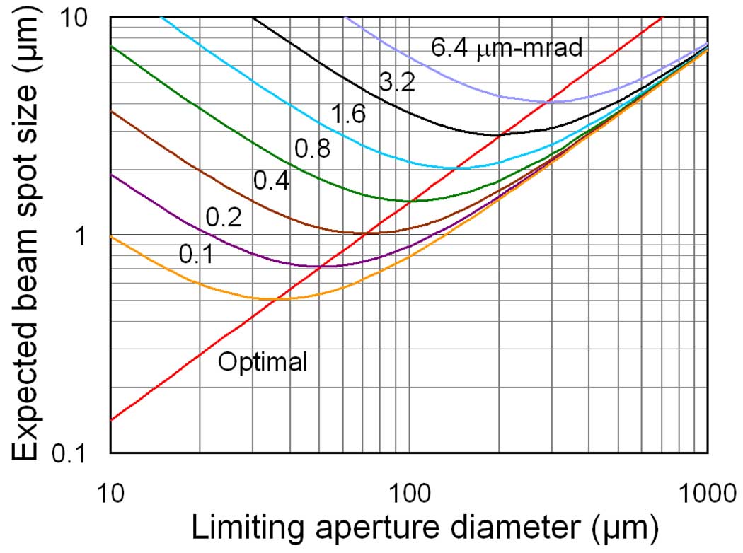
Calculations of the beam spot size for our lens geometry were made using the computer software GIOS (General Ion Optic System) [8]. The results of calculations of beam spot size as a function of object aperture diameter for a series of diameters of the angular divergence limiting aperture located at the entrance to the first lens were fit as a family of curves. The fit was used to generate plots of beam spot size as a function of the divergence aperture diameter (Fig. 4). As can be seen, for a given emittance, there is a combination of object aperture and divergence limiting aperture diameters at which the beam spot size is a minimum. This combination gives the best particle transmission for that beam diameter. The graph also shows the smallest beam spot size that can be obtained by only reducing the object aperture size with a fixed divergence aperture.
Fig. 4.
Results of calculations of the beam spot diameter produced by the compound electrostatic quadrupole triplet as a function of the diameter of the angular divergence limiting aperture for various diameters of the object aperture. The curves are for constant emission (µm-mrad). The values of the limiting aperture diameter that results in the minimum beam spot diameter for given particle transmission are connected by the diagonal line.
Construction and Assembly
The components of the lenses have been machined to very high precision. The rods are made from Macor (Corning, Inc., Corning, NY), a machinable glass ceramic that has no outgassing and zero porosity. The rods were ground to a diameter of 10 mm ±6 µm and a straightness of ±13 µm over their length, then machined to 300 mm ±13 µm in length. During machining, the distance of each electrode on each rod (including the ground electrodes between the quadrupole elements) was measured from one “reference” rod end, so that the positions of the electrodes from the reference ends on each rod were kept constant within ±5 µm. The first and third quadrupoles have elements that are 51.83 mm long. The second (center) quadrupole has elements 96.34 mm long. The insulating section between the end of each quadrupole element and the nearest ground plane is 10.03 mm long (Fig. 1).
Each titanium cross is made of 2 interlocking straight sections (Fig. 2–3). These pieces were ground and lapped to a precision of 0.4 µm in thickness to ensure the spacing between the rods. Holes 2.3 mm in diameter are drilled in the centers of the cross pieces to transmit the ion beam. The angle between the rods is set by the V-blocks, which are ground to an angle of 90±0.2°. A tapped hole at the center of each electrode is used for attachment of the voltage supply.
After machining, the rods were sent out for ion implantation of the cylindrical surfaces (see below). When the rods returned from the implantation process, the exposed insulating sections of the rods were masked. The sections that are the electrodes and grounds were plated over the entire cylindrical surface with a thin titanium “adhesive” layer and then with a layer of gold 1 µm thick using a sputtering technique to make the surfaces conductive.
The electrodes were assembled on a granite surface plate with a surface finish of 0.33 µm over 4 square feet. A special fixture was used to position the V-block and cross assemblies accurately. The V-blocks are adjusted carefully so that when the lenses are placed on the surface plate they have a deviation in camber (straightness) of less than 5 µm in any direction over their entire 300 mm length. A ground strap connects all the ground planes (V-blocks). When the lens is assembled, the center-to-center distance between opposing rods is 20 mm, resulting in a lens bore of 10 mm (Fig. 2).
The V-blocks and crosses do not form a smooth surface, making poor ground planes. In order to correct this problem, a thin aluminum cover was placed over the surfaces of the V-blocks and crosses that face electrodes (all but the two end faces). In order to fit closely around the four rods, the cover is made in three pieces: an inner cross that fits between the rods and two ring halves that cover the area outside the rods. The assembly fits into recesses on the V-blocks (Fig. 3), making a smooth surface.
The lenses were installed in a stainless steel tube 2.5 m long with an inside diameter of 63.5 mm. At each end of each lens there are four screws that pass through the tube and are used to adjust the position of the lens in the tube. At the end of the tube near the focal point of the system a disc with a spherical surface on one side is attached to the outside of the tube. When the lens system is mounted on the beam line, the spherical surface sits in a mating support that forms a ball-and-socket gimbal, which allows the lens to be pivoted about its focal point for alignment with the charged particle beam.
To assemble the compound lens, a transit was aligned with the center axis of a large lathe by observing targets mounted in the head stock and the tail center of the lathe. The first quadrupole triplet was mounted in the stainless steel tube and then the tube was mounted in the lathe. Cross-hair targets were set in-between the 4 ceramic rods at both ends of the triplet lens. The disc on the end of the tube was set to run true to the axis of the lathe within a few microns and the far end of the tube was supported in a steady rest that had been preset to the correct height. The mounting screws at each end of the lens were adjusted to align the lens with the center axis of the lathe as viewed through the transit. When the lens was aligned and locked in place, the targets were removed and the second triplet lens was mounted in the tube and the same cross hair targets mounted in it. Then the second lens was aligned in the same manner as the first.
Development
An initial single quadrupole quadruplet lens of construction similar to that for the triplet lenses was constructed as a test of the design. This lens was tested on a separate beam line and eventually achieved the predicted demagnification factor of 4, focusing the beam passing through an aperture with a diameter of 8 µm to a beam spot with a diameter of 2 µm whose position was very stable.
Several modifications to the initial lens design have been made during development.
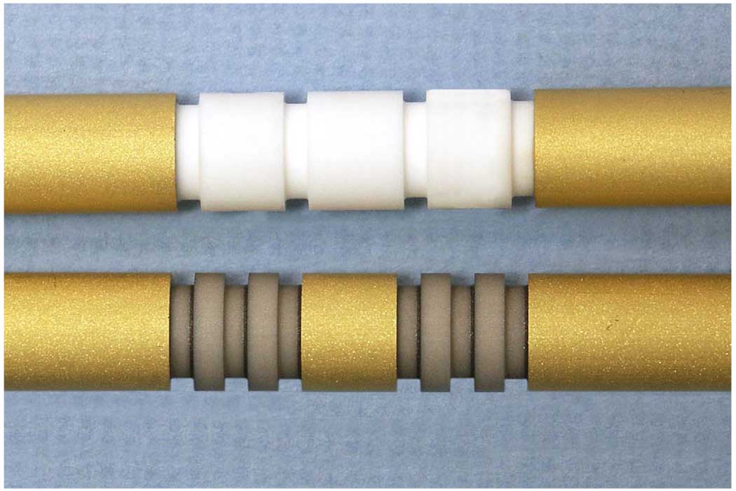
This initial prototype lens required the voltage to be brought up to the operating potential of 15 kV over several days. Even then there would be occasional sparking while increasing the voltage and even after reaching the desired voltage. The addition of another groove in the middle of each insulating section on the ceramic rods reduced this problem considerably (Fig. 5). The surfaces of the ceramic rods where the crosses and V-blocks are attached were initially left bare but later were gold plated, as the electrodes are to better define the ground planes.
Fig. 5.
Comparison of the original (top) and the final (bottom) designs for the insulating sections between the electrodes and ground.
Another modification was the implantation of 150 keV platinum ions on the surface of the ceramic rods to make them slightly conductive. These low energy ions have a penetration normal to the surface of about 220 Å [9] and therefore do not affect the bulk resistivity of the ceramic. The ion implantation was performed by Dr. Ian Brown of the Lawrence Berkeley National Laboratory using a fixture we designed and constructed. This fixture rotates six ceramic rods through the broad ion beam and rotates each rod about its axis to produce uniform implantation over the entire cylindrical surface of all the rods. Halfway through the implantation process the rods were reversed to make implantation more uniform from end to end. The increased surface conduction helps to carry away charge from scattered particles that collide with the rods and reduces the electric field at the edges of each electrode, thus reducing electrical breakdown. In the final design, approximately 125 keV platinum ions were implanted in the ceramic rods at a fluence of 1016 ions/cm2 at the High Current Electronics Institute, Tomsk, Russia, producing a surface resistivity of about 1012 Ω/square [9]. Under 30× magnification, the there was no noticeable change observed in the smoothness of the surfaces of the insulators.
Beam optics
The charged particle beam is produced by the RARAF 5.5 MV Singletron accelerator (High Voltage Engineering Europa, Amersfoort, The Netherlands) The accelerator has a voltage ripple of less than 100 V peak to peak at a terminal potential of 3.75 MV. The RF ion source can produce beams of protons, deuterons and 4He ions.
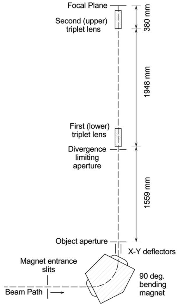
The beam transport and focusing arrangement is shown in Fig. 6. The charged particle beam passes through a set of four adjustable slits that are used to limit the angle of the beam entering the 90°magnet that is used to bend the beam vertically upward. The magnet was designed to focus the beam in both directions, not just the bend plane, so that a circular beam spot can be produced at its focal point.
Fig. 6.
Diagram of the charged particle beam optics system.
The object aperture is a set of two pairs of ground tungsten carbide rods, each pair at a slight angle from parallel (Technisches Büro S. Fischer, Ober-Ramstadt, Germany). By moving the pairs of rods in and out using stepper motors, the size of the aperture can be changed from <1 µm to 150 µm. The aperture is placed at the focal point of the 90°magnet.
For the focusing system to work predictably, the beam at the object aperture must have a known phase space property in which the angular deviation of a particle from the center of the beam is not correlated with position in the beam (an upright elipse being the simplest). To decouple the angular deviations of the particles from their positions without introducing a spread in energy, an X-Y electrostatic deflector was constructed and inserted just below the object aperture. The beam spot is considerably larger than the object aperture so that different portions of the beam spot are transmitted as the beam is deflected. The deflector design is very similar to that for the focusing lens except that there is only one set of 4 poles. The electrodes are driven by triangular waves from 2 pairs of power supplies operating at different frequencies selected to avoid repetitive positioning. Opposing electrodes are driven by opposite polarities. The operating voltage is about 2 kV peak-to-peak.
The entire length of the microbeam focusing system from the object aperture to the focal point is 3887 mm. The entrance of the first (lower) quadrupole triplet is 1559 mm from the object aperture and the distance between the two lenses is 1948 mm. A divergence limiting aperture is placed at the entrance of the first lens to define the angular acceptance of the system. The focal point of the lens system is 100 mm from the end of the last lens.
Scattering in the exit window of the beam transport system can increase the effective diameter of the charged particle beam, becoming more important with increasing distance between the sample and the surface of the window. The standard beam exit window on our system is a piece of silicon nitride 5 mm × 5 mm × 200 µm thick with a transmission window 1.5 mm × 1.5 mm × 500 nm thick (Silson Ltd., Northampton, UK). For ultimate focusing capability, a transmission window 0.25 mm × 0.25 mm × 100 nm thick can be used to reduce particle scattering to a minimum.
Results
In order to measure the diameter of the charged particle beam, we routinely use a “knife-edge” scan. A strip of thin material is moved across the beam in two directions orthogonal to each other using a stage with 0.1 µm resolution (Nano-LP200, Mad City Labs, Madison, WI). The material is thin enough to reduce the energy of the beam noticeably but not stop it, so that the transmitted ions still can be detected by a silicon surface barrier detector. Presently we are using strips of Havar foil 3 µm thick with the edges lapped to make them smooth and square. The ratio of the number of particles in the reduced-energy peak to the total number of particles indicates the percentage of the beam spot that has been occluded. A linear fit of the count ratio versus stage position is made from the approximately the 5% level to approximately the 95% level of the ratio and extrapolated to 0% and 100% (Fig. 7). The difference in the stage positions at these two points is taken as the width of the beam in that direction.
Fig. 7.
Typical orthogonal knife-edge scans across a focused 6.0 MeV 4He beam. The lines are linear least-squares fits to the filled points.
Maximum demagnification is achieved when the object aperture is aligned with the lens and the voltages on the lens elements are optimized. A computer algorithm is used to automate voltage adjustment in the search for the smallest beam diameter. Measurements of the beam width in the X and Y stage directions are taken with three sets of slightly differing lens voltages. The lens voltages are controlled by the computer using a digital-to analog converter (DAC). The root mean square of the measurements in the two directions is taken as the beam diameter. A computer algorithm based on the simplex method of Nelder and Mead [10] calculates the slope of the surface to determine the next voltages to use. The last three measurements are used iteratively to calculate the next voltages to use. The voltage step size can be adjusted for a broad or fine search and termination limits are set for the minimum change in beam spot size and the maximum number of iterations. Voltages of about 9 kV are required on the lenses to focus 6 MeV 4He ions or 3.0 MeV protons. We have decided to make voltage C equal to voltage A, requiring only four voltage supplies (+A, −B, +A), (−A, +B, −A) instead of six.
The position of the entrance of the lens tube containing the two triplet lenses was also adjusted to align the lens with the beam path. The lens tube is set in a gimbal near the end of the second triplet and the bottom of the tube can be moved remotely using stepping motors. A search of positions was made, taking measurements of the beam spot size in both directions at each lens position to obtain the best alignment (smallest diameter beam).
After careful adjustment of the lens voltages and the position of the of the lens tube entrance position, beam spot scans of 0.68 µm in the X direction and 0.90 µm in the Y direction have been obtained for 6 MeV 4He ions using an object aperture 30 µm in diameter and a limiting aperture 50 µm in diameter. The root mean square (RMS) value of the beam diameter is 0.8 µm, indicating a total demagnification factor of approximately 38, which is in good agreement with the calculated value of 36.
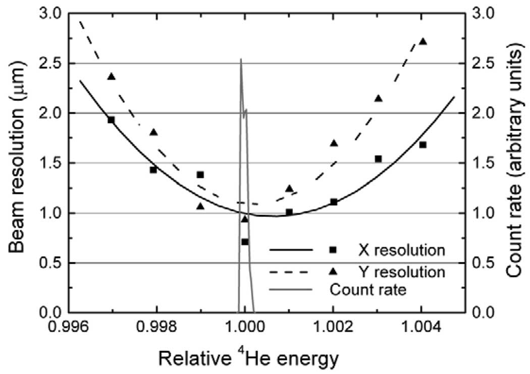
Measurements were made of the sensitivity of the resolution (beam spot diameter) to changes in the energy of the ions (Fig. 8). To facilitate the measurements, the ion energy and bending magnet field were held constant and the voltages on the lenses were changed. Since the voltage required to focus a beam is directly proportional to the energy, the fractional change in lens voltage was the same as the change in beam energy would have been. It requires a 0.2 to 0.3% energy change (12–18 keV at 6 MeV) to increase the beam spot size by ~50%. Measurements of the acceptance of the beam line optics were made by keeping the lens voltage and bending magnet field constant and varying the energy of the ion beam (Fig. 8). The full width of the acceptance at half maximum is less than 0.02% (1.2 keV at 6 MeV).
Fig. 8.
Measurement of the degradation of the resolution for 6 MeV 4He ions as a function of the relative ion beam energy. The curved lines are least squares fits to the measured points using a second-order polynomial. Also shown is the energy acceptance of our beam line optics (solid gray line).
Discussion
Low-current physics microprobes typically have beam spot sizes in the range of 50 to 100 nm [5] and are being pushed to 30 nm [11] and smaller, however these beam spots are produced in vacuum. To focus the beam in air, a thin vacuum window is usually employed. Scattering in even a very thin window (e.g., 200 nm Si3N4) increases the size of the focused beam spot. The effect of the scattered ions increases with distance from the exit window, making it important to have samples as close to the window as possible. A number of focused external charged particle microbeam facilities for biological applications are now in existence, several with sub-micron beam spot sizes. The beam spot size of the Columbia University microbeam is comparable to the smallest of these beams.
Several facilities use focused beams of light ions (protons and He ions). Among these are: LIPSION at the University of Leipzig (Germany), which has a “hit accuracy” better than 0.5 µm [12]; the PTB (Physikalisch-Technische Bundesanstalt) microbeam in Braunscweig (Germany), which has a beam diameter of ~2 µm (fwhm) [13]; and the particle irradiation system SPICE (single particle irradiation to cell) at the National Institute of Radiological Sciences (NIRS) in Chiba (Japan) that can produce a beam spot approximately 10 µm in diameter [14].
The heavy ion microprobe SNAKE (Supraleitendes Nanoskop für Angewandte Kernphysikalische Experimente) at the University of Munich (Germany) can focus beams of protons and heavy ions to abeam spot less than 0.5 µm in diameter [15]. GSI (Gesellschaft für Schwerionenforschung) in Darmstadt (Germany) has a heavy ion microprobe that focuses the beam to ~0.7 × 0.5 µm [16]. These facilities both produce ion beams of light ions (protons and helium ions) in addition to beams of heavy ions.
Conclusions
We have developed a compound electrostatic quadrupole triplet lens system that has focused a beam of 6 MeV 4He ions in air to a diameter 0.8 µm. The measured demagnification is 38, in good agreement with the calculated demagnification of 36. The quadrupole electrodes can withstand voltages high enough to focus 4He ions up to 10 MeV and protons up to 5 MeV. The design of the quadrupole triplets is novel in that alignment is made through construction and the relative strengths of the quadrupoles are accomplished by the lengths of the elements, so that the magnitude of the voltages required for focusing are nearly identical. The lens design employs Russian symmetry for the quadrupole elements. Additional adjustment of the lens voltages and lens alignment is expected to result in a beam diameter of 0.5 µm for an object aperture of 16 µm.
Acknowledgments
The Radiological Research Accelerator Facility (RARAF) is an NIH supported Resource Center through grants EB-002033 (NIBIB) and CA-49062 (NCI).
Footnotes
Publisher's Disclaimer: This is a PDF file of an unedited manuscript that has been accepted for publication. As a service to our customers we are providing this early version of the manuscript. The manuscript will undergo copyediting, typesetting, and review of the resulting proof before it is published in its final citable form. Please note that during the production process errors may be discovered which could affect the content, and all legal disclaimers that apply to the journal pertain.
References
- 1.Geard CR, Brenner DJ, Randers-Pehrson G, Marino SA. Nucl. Inst. and Meth. B. 1991;54:411–416. [Google Scholar]
- 2.Randers-Pehrson G, Geard CR, Johnson GW, Brenner DJ. Radiat. Res. 2001;156:210–214. doi: 10.1667/0033-7587(2001)156[0210:tcusim]2.0.co;2. [DOI] [PubMed] [Google Scholar]
- 3.Zirkle RE, Bloom W. Science. 1953;117:487–493. doi: 10.1126/science.117.3045.487. [DOI] [PubMed] [Google Scholar]
- 4.Legge GJF. Nucl. Instrum. and Meth. B. 1997;130:9–19. [Google Scholar]
- 5.Jameson DN. Nucl. Instrum. and Meth. B. 181;2001:1–11. [Google Scholar]
- 6.Dymnikov AD, Brenner DJ, Johnson G, Randers-Pehrson G. Rev. Sci. Inst. 2000;71:1646–1650. [Google Scholar]
- 7.Dymnikov AD, Hellborg R. Nucl. Instr. and Meth. A. 1993;3:323–342. [Google Scholar]
- 8.Wollnik H, Hartmann B, Berz M. AIP Conf. Proc; 1988. pp. 74–85. [Google Scholar]
- 9.Nikolaev A, Oks EM, Savkin K, Yu. Yushkov G, Brenner DJ, Johnson G, Randers-Pehrson G, Brown IG, MacGill RA. Sur. Coat. Tech. 2007;201:8120–8122. [Google Scholar]
- 10.Press WH. Numerical Recipes in C: the Art of Scientific Computing. Second ed. New York: Cambridge University Press; 1992. pp. 408–412. [Google Scholar]
- 11.van Kan JA, Shao PG, Molter P, Saumer M, Bettiol AA, Osipowicz T, Watt F. Nucl. Instr. and Meth. B. 2005;231:170–175. [Google Scholar]
- 12.Fiedler A, Reinert T, Tanner J, Butz T. Nucl. Instr. and Meth. B. 2007;260:169–173. [Google Scholar]
- 13.Greif K, Beverung W, Langner F, Frankenberg D, Gellhaus A, Banaz-Yasar F. Radiat. Prot. Dosimetry. 2006;122:313–315. doi: 10.1093/rpd/ncl436. [DOI] [PubMed] [Google Scholar]
- 14.Imaseki H, Ishikawa T, Iso H, Konishi T, Suya N, Hamano T, Wang X, Yasuda N, Yukawa M. Nucl. Instr. and Meth. B. 2007;260:81–84. [Google Scholar]
- 15.Dollinger G, Bergmaier A, Hauptner A, Dietzel S, Drexler GA, Greubel C, Hable V, Reichart P, Krucken R, Cremer T, Friedl AA. Nucl. Instr. and Meth. B. 2006;249:270–277. [Google Scholar]
- 16.Voss KO, Fournier C, Taucher-Scholz G. New J. Phys. 2008;10:075011. [Google Scholar]


