Abstract
The combination of adaptive optics (AO) technology with optical coherence tomography (OCT) instrumentation for imaging the retina has proven to be a valuable tool for clinicians and researchers in understanding the healthy and diseased eye. The micrometer-isotropic resolution achieved by such a system allows imaging of the retina at a cellular level, however imaging of some cell types remains elusive. Improvement in contrast rather than resolution is needed and can be achieved through better AO correction of wavefront aberration. A common tool for assessing and ultimately improving AO system performance is the development of an error budget. Specifically, this is a list of the magnitude of the constituent residual errors of an optical system so that resources can be directed towards efficient performance improvement. Here we present an error budget developed for the UC Davis AO-OCT instrument indicating that bandwidth and controller errors are the limiting errors of our AO system, which should be corrected first to improve performance. We also discuss the scaling of error sources for different subjects and the need to improve the robustness of the system by addressing subject variability.
Keywords: Adaptive Optics, Optical Coherence Tomography, imaging systems, Medical Optics Instrumentation
1. Introduction
The adaptive optics (AO)-optical coherence tomography (OCT) system at UC Davis has been in use for several years and has demonstrated the utility of this technology for microscopic, volumetric, in vivo retinal imaging [1]. The combined technology of traditional OCT and adaptive optics provides excellent resolution in all three dimensions. We estimate that our AO-OCT instrument has isotropic resolution of 3.5 μm [2]. This level of resolution allows cellular level imaging of the retina. Indeed AO-OCT instruments have imaged cells in the photoreceptor layer. Other cells, however, are much harder to image because they require higher contrast, rather than a higher resolution imaging system. In astronomical adaptive optics, improvements in AO system performance (so called Extreme Adaptive Optics systems) can be used to improve the contrast of AO images [3]. Improving the performance of our existing system, while informing the design of the next generation system could allow better contrast in retinal imaging. Another goal of improved system performance is system robustness. Very often individuals who are scientifically interesting have retinal conditions that are difficult to image because of large wavefront aberrations, low light reflectance and in some cases for unknown reasons. A better understanding of the scaling of error sources within the AO system will help identify areas where robustness could be improved.
Developing an error budget is a common tool for improved performance and system design in astronomical AO systems [4, 5]. This process for vision science systems has received scant attention. Articles in vision science focusing on the performance of individual AO components (e.g. Deformable mirrors [6, 7]) or the size of individual error sources (e.g. Bandwidth errors [8, 9]) are more common.
Compiling an error budget entails an analysis of the sources of residual wavefront error (WFE). The relative size of the sources of residual error will prioritize system upgrades and inform the design of future systems. In general, an AO system error budget must include an analysis of three categories of residual WFE: errors in measuring the phase, errors caused by limitations of the deformable mirrors (DMs), and errors introduced by temporal variation. Ideally an error budget would be calculated for a system in the design phase, but it can also be used to assess and improve performance after construction, as often the difference between designed performance and actual performance is significant. Important tradeoffs for system improvements can also be examined with an error budget. For example increasing the sub-apertures in the AO system can reduce high-order errors and aliasing, but because of reduced light per sub-aperture could increase measurement error. In this paper we discuss both the techniques for characterizing these error sources and our measurement of them for the AO-OCT system.
An error budget generally ascribes a value in nm rms (or perhaps a small range of values) to each residual error source and while this is useful for understanding the relative magnitude of the residual errors it will not provide all the information needed to understand system performance. In particular it does not assess system performance for changing conditions such as, in the case of vision science systems, the variability between subjects. When calculating the magnitude of individual errors it is important to examine the scaling of those errors under different conditions (e.g. low light levels or large wavefront aberrations). We suggest that a robust AO system for vision science would have multiple modes of operation to accommodate the differences between subjects. We will discuss the types of modes that might be useful and how the monitoring of individual error sources might inform the implementation of those modes.
2. System description
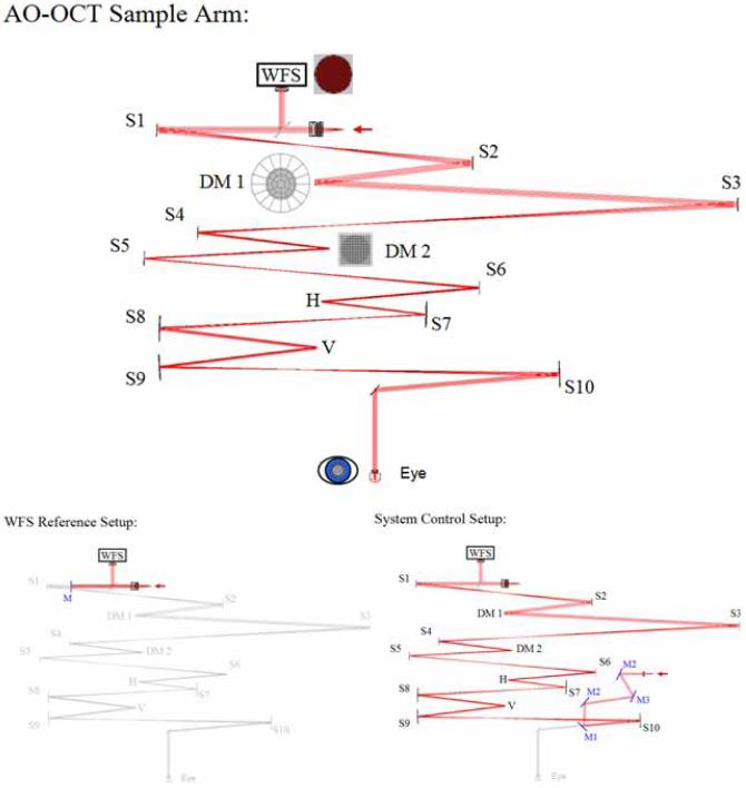
OCT is an imaging modality that allows high volumetric resolution (few μm) mapping of the scattering intensity from the sample. OCT is similar to ultrasound techniques, but the intensity of back-scattered light rather than sound waves is measured as a function of depth (in the tissue). Due to the fast speed of light, direct measurements of the time of flight, as in ultrasound, are not possible. Instead a low-coherence light source (or swept laser) and an interferometer with a sample arm and a mirror in the reference arm have to be implemented to reconstruct the depth position of each back-scattered photon. The UC Davis AO-OCT system is described in previous publications [10]. The sample arm contains the AO subsystem and thus is the focus of this article. It is shown in Fig. 1. The major components of the AO subsystem are the 20 × 20 Shack-Hartmann wavefront sensor (WFS), and two DMs. Spherical mirrors (indicated by S1-S10 in the diagram) re-image the pupil. The system uses a bimorph DM made by AOptix Technologies, Inc. for low-order, high-stroke correction [11] and a 140-actuator micro-electrical-mechanical-system (MEMS) DM made by Boston Micromachines Corporation (BMC) for high-order correction [12]. These are indicated by DM1 and DM2 in the layout. Like other confocal imaging modalities, OCT requires the sample arm to scan the retina to produce the science image. Horizontal and vertical scanners are located at pupil planes and indicated by H and V in the diagram. For some characterization tasks we use a model eye, consisting of a lens with a paper ‘retina’ at the focus.
Fig. 1.
Layout of the AO-OCT sample arm. The system has three modes of operation imaging mode (labeled AO Sample arm), WFS reference set up used for measuring reference centroids and System Control set up which is a single pass mode used for measuring the control matrix for each DM. The system uses a 20 × 20 Shack-Hartmann wavefront sensor, a AOptix bimorph deformable mirror for low-order correction and a MEMS deformable mirror for high-order correction. Horizontal and vertical scanners are used to scan the retina. S1 - S10 denote spherical mirrors used to re-image the pupil plane. A sample arm like this could also be used for other imaging modalities, such as AO-SLO.
A description of the basic AO operation is available from several previous publications [2, 13]; it is summarized here for the convenience of the reader. There are three modes of operation of the system. WFS reference set up is a calibration mode used to measure the reference centroids of the WFS. In this mode (pictured in Fig. 1 bottom left) a flat mirror is placed in front of S1 and is adjusted to maximize back-coupled light to the input fiber, then the centroid positions are measured. In system control set up the system is operated in single pass: a fiber and collimating lens are placed in the eye equivalent position and adjusted to maximize the light coupled back to the input fiber used in double-pass operation (See Fig. 1 bottom right). The control matrices (one for each DM) are calculated from the system matrix found by measuring the effect on the WFS of moving each actuator in the system in single-pass mode. Typically the AOptix bimorph is measured first, then held flat while the MEMS is measured. During closed-loop operation the calculated control matrices are used to close the loop on the two DMs consecutively [10]. In normal operation the system is operated in double-pass where light is both input and measured from the eye (See top of Fig. 1). The sample arm of the AO-OCT instrument can be used for AO-SLO with minor modifications as in Chen et al. [14]. During closed-loop operation the rms of centroid displacements is used to gauge performance.
When saving closed-loop results three types of data can be archived: the raw WFS images, the centroid positions, and the system parameters. It is important to archive data from a variety of subjects to assess system performance, but due to space constraints images are not automatically archived. Adding more real-time system assessment might reduce the need for archiving data, but could slow performance as well. The centroids are calculated during closed loop operations using a thresholded center of mass. The WFS images are saved optionally because of their size but are needed to calculate measurement error. During closed loop the vector matrix multiplication (VMM) controller does not provide a wavefront reconstruction and in post processing, a Fourier Transform reconstructor (FTR) is used [15]. A VMM reconstruction would be based on the control matrix of the MEMS and thus would only be 12 by 12 pixels, while the WFS acquires 20 by 20 slopes. Using the FTR allows us to take advantage of the full sampling of the WFS. Of course there are many methods of wavefront reconstruction, and each type will introduce errors to the residual wavefront either during closed loop or in post processing. A reconstruction based solely on Zernike modes is probably not optimal for the AO-OCT system described here as the MEMS can correct (and introduces) high-spatial frequency errors that may not be well represented in Zernike modes alone. The FTR and its more advanced iterations are described in several publications [15, 16] and it has been implemented on several systems [5, 17, 18]. Here we describe only the basics of FTR implementation. Generally the slopes calculated during closed loop are divided into x slope and y slope arrays where the area outside the aperture has been modified to solve the boundary problem. Then the arrays are Fourier transformed, multiplied by a filter based on the WFS geometry, combined into one wavefront and inverse transformed. This could be done in the realtime system, but the alignment between the calculated wavefront and the wavefront corrector is critical. In the case of a realtime controller a more sophisticated filter might be desirable [18]. We are investigating using FTR on the testbed for closed-loop correction [19].
An important consideration for a vision system sample arm is light throughput. Light needed for wavefront sensing and imaging is limited by both the amount of light that can be safely delivered to the eye and the limited reflectivity of the eye. There are several light sources for the system. The human subject data presented here were collected with a super luminescent diode (SLD) with a center wavelength of 836 nm and a bandwidth of 112 nm with an axial resolution of approximately 3.5 μm (larger bandwidth sources increase OCT axial resolution). The light budget for the AO-OCT sample arm was calculated using assumed values for reflectivity/transmisivity and then compared to values measured with a power meter at each focus. Adjustments in the theoretical light budget were made to match experimental measurements generating an accurate system light budget. The system currently delivers approximately 375 μW to the eye with about 29% throughput. The light level is set according to safety standards and not the maximum output of the SLD currently in use. The most significant loss of light occurs at the MEMS DM, which has effectively 70% reflectivity. The MEMS mirror is gold coated, however the protective window in front of it has an anti-reflective coating for the visible. Ghost images from the window are significant. Operating in double pass introduces scattered light from the MEMS device, which will be discussed in section 5. Since this data was collected we have replaced the MEMS DM in the system to reduce scatter and improve throughput. Presumably the light returning to the WFS experiences the same losses as the input light, but is of course reduced by the reflectivity of the eye.
3. Results and discussion
AO system characterization generally starts with the residual WFE measured by the WFS. Typically this is reported as an rms value, although some groups calculate the PSF from the reconstructed wavefront and use Strehl values as the performance metric. It should be noted that both strehl and rms WFE are imperfect metrics of system performance. Strehl ratio can be calculated in a variety of ways, making comparisons between systems problematic [20] and high strehl ratios also do not necessarily translate to high-contrast images. Using rms values is also incomplete because it does not include information about spatial frequency of WFE, which can often be revealing. For example, a wavefront error generated by a single bad actuator can have the same rms as a wavefront with all of the actuators slightly displaced from ideal, but the error that generated these wavefronts is probably quite different. A system which only records strehl and/or rms values maybe missing valuable insights into system performance. Additionally, WFE measured by the WFS contains some ambiguities. The reconstructed wavefront is limited by the reconstruction algorithm used— for example a very limited modal reconstruction will underestimate WFE by ignoring high-spatial frequency errors. The WFS measurement itself is limited by the measurement error caused by noise in the CCD, error of the centroiding algorithm, etc. Furthermore the WFS cannot measure all errors that affect performance. In particular calibration error could be significant and yet unmeasured by the WFS. In spite of these shortfalls the measured residual WFE of the WFS is the fastest way to assess and possibly improve system performance. In the case of the AO-OCT system the WFS is particulary helpful because, like many vision science AO systems, it is over-sampled compared to correction.
During OCT image acquisition the closed-loop system does not explicitly reconstruct the wavefront. When AO data are saved the system parameters and the calculated slopes for each iteration are always collected and the system can also be configured to save the raw WFS images. Typically the slopes are used to reconstruct the wavefronts using the FTR in post-processing. The WFS images can be used to calculate light levels (used for example to calculate measurement error in Section 3.2). The reconstructed wavefronts are also useful for understanding residual errors and both spatial power spectrum analysis and differencing are common processing techniques used for the analysis presented here.
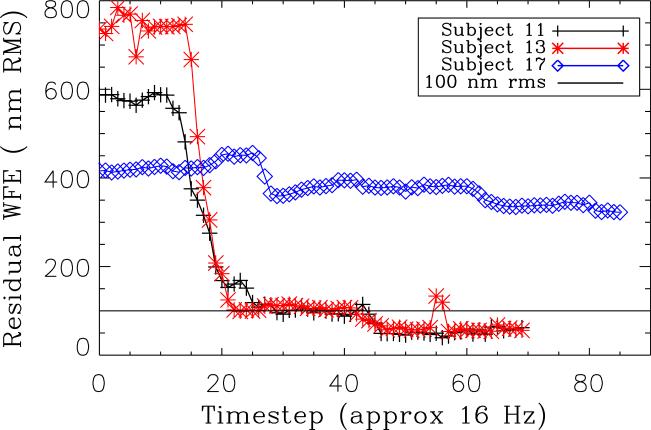
AO closed-loop data were collected for a series of subjects to evaluate system performance. Typical values for good correction are approximately 100 nm rms. It should be noted that subjects are selected for imaging with a bias towards subjects we expect to correct well. Generally this eliminates subjects with large wavefront aberrations, poor reflectivity or poor fixation. Additionally, AO data are not recorded for every OCT image, or even necessarily every subject. With this in mind the conclusions drawn here based on this series of subjects should be generally applicable to the instrument, but it is also important to consider more extreme cases when the system might not perform as well. The closed-loop rms WFE values are shown for three subjects in Fig.2. Two of the subjects have good correction, and one has poor correction (possibly caused by a small pupil). We are interested in both the limitations to good correction and why some subjects have poor correction. The more subjects that can be imaged well, the more robust the scientific results.
Fig. 2.
Residual WFE in nm RMS for three subjects. Two of the subjects show typical good correction and the third is representative of a small group of subjects with poor correction. Good correction typically leads to WFEs of about 100 nm rms.
3.1. Deformable mirror error
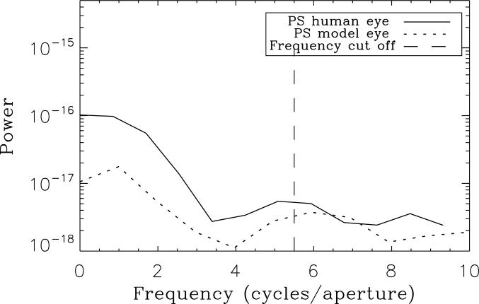
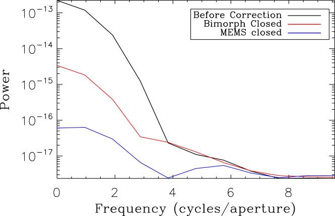
In astronomy systems fitting error must be estimated based on models of the input aberrations (e.g. Kolmogorov turbulence), but often in vision systems the WFS is over-sampled compared to the DM allowing some fitting error to be measured by the WFS. Fitting error arises because not all spatial frequencies can be corrected by the DMs in the system. The control radius, or the highest-spatial frequency that can be controlled is generally equal to approximately 1/2 the number of DM actuators across the aperture, about 5.5 cycles/aperture, for the MEMS DM. Note that 11 actuators, not the 12 available, across the MEMS DM are used in our system because on this particular device the outer row/column of actuators are not fully covered by the gold coating. The control radius of the system also depends on the influence function of the DM. DMs with broad influence functions (i.e. high coupling between actuators) will have reduced control of high spatial frequencies. An excellent discussion of statistical calculations of fitting error based on measured influence functions can be found in Devaney et al. [6]. The broad influence function and actuator geometry make it difficult to calculate a control radius for the AOptix bimorph DM, however from power spectra it is < 4 cycles/aperture. Any WFE (measured or not) with a higher-spatial frequency that cannot be corrected is out-of-band. Ideally all residual WFE would be out-of-band, because all errors that could be corrected, would be. In practice other error sources limit in-band correction. The model eye, for example has a total WFE of 48 nm rms with 37 nm out-of-band. Subtracting in quadrature indicates that 31 nm rms are still uncorrected in-band. In the human subjects the in-band error is worse. For subject 13 total residual WFE is 69 nm rms, and only 28 nm rms are out-of-band. For the well-corrected subjects included in this study the average WFE is 95 nm rms, with an average of 89 nm rms in-band. Out of band errors are thus 33 nm rms, with a standard deviation of ± 20 nm rms. These values for higher order error are slightly higher than expected by eye models[6, 21, 22] probably because of the higher-order error introduced by the MEMS DM itself. One way to understand the distribution of spatial frequencies in residual error is to calculate the power spectrum of the wavefront. Figure 3 compares the radially averaged power spectra of the model eye and subject 13. It is immediately obvious that in both cases the residual in-band WFE is mostly low order. These errors should be easily corrected by either the AOptix bimorph or the MEMS. In only one of the subjects (who has excellent vision) were low-order errors not the dominate source of in-band error. Figure 4 compares the power spectra of the uncorrected wavefront for subject 13 to the wavefront after the AOptix bimorph correction is applied and after the MEMS correction is applied (with bimorph still in its corrected position). Low-order errors are reduced by both DMs, but after correction in subject 13 the WFE from 0-2 cycles per aperture is 50 nm rms, and on average this error is 63 nm rms, a large portion of in-band error. Clearly the AOptix bimorph is not correcting as much low-order error as we would expect. We've also noted in practice that the ability of the AOptix bimorph to correct large amounts of astigmatism is limited.
Fig. 3.
Power spectra for a converged closed-loop wavefront of a human subject compared to the model eye. Correctable in-band errors are dominated by low-order error.
Fig. 4.
Power spectra of a human subject wavefront, before correction after AOptix bimorph correction, and after MEMS correction. The curve labeled MEMS closed is the same as in Fig. 3. Low-order residual errors are reduced in each case but remain a large source of error.
In addition to fitting error, the DM will introduce errors based on the ability of each individual actuator to go to the position demanded by the control system. Generally this voltage step size is limited by the resolution of the drive electronics. The MEMS device has an actuator precision of 1%, which corresponds to WFE of 12 nm rms. The AOptix bimorph mirror with its 16-bit electronics introduces negligible step size error.
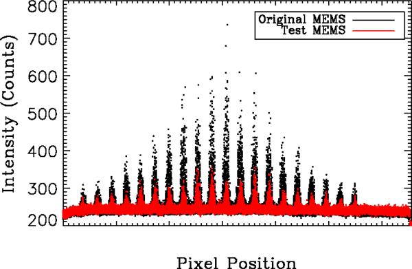
Another DM introduced error can be scattered light. The original MEMS DM in the AO-OCT system has significant backscatter into the WFS when the system is operated in double pass. BMC suggested that the gold surface of the original MEMS DM was contaminated by outgassing of the glue attaching the MEMS window. To test this BMC provided a MEMS DM without a window and with good surface quality. The backscatter from the two MEMS is compared in Fig. 5. Backscatter in the WFS is measured without a subject or model eye in the system under normal (dark) lighting conditions. Clearly the test device has greatly reduced backscatter compared to the original MEMS. When the MEMS mirror is replaced with a flat mirror the backscatter is nearly identical suggesting that remaining backscatter is systematic and not caused exclusively by the MEMS. For subjects with strong retinal reflectivity the scatter from the MEMS is probably not a significant source of residual error, but because the scatter is a portion of the input light it remains at the same level for subjects with poor reflectivity and can introduce errors in centroiding as well as make the subject more difficult to align.
Fig. 5.
Plot of intensity at every pixel for the WFS for backscattered light in the system. These images are captured when no subject is in the system, and in an ideal system would be only CCD noise. Contamination of the gold surface caused by outgassing of the glue used to attach the MEMS window introduced significant backscatter on the original MEMS device, but a newer test device provided by BMC without the contamination has reduced backscatter. The backscatter of the test device is nearly identical to backscatter from a flat mirror (not shown).
3.2. Measurement error
Measurement error is a metric of how well the WFS can measure the wavefront to be corrected. In this article we separate measurement error (errors introduced by centroiding errors in the WFS) from reconstruction error (see Section 3.4). Centroiding error is calculated analytically, roughly based on signal to noise, and then converted to wavefront error using the wavefront reconstructor. Analytical expressions for calculating centroiding error are derived in several papers [23, 24, 25], depending on the type of centroiding that is used. For the current system using thresholded center of mass the most appropriate equation is the detector-limited equation from Nicolle et al. [23]. We repeat it here for the convenience of the reader:
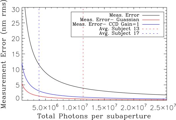
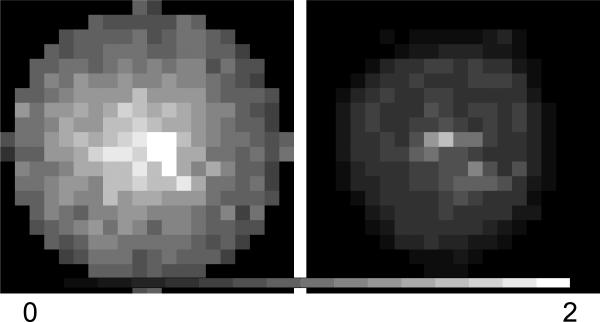
Note that this equation is for the variance of centroid position, σ2, and standard deviation is used in the error budget. We vary the total number of photons per sub-aperture, Nph, while readnoise, σdet, number of pixels per sub-aperture, , and FWHM of the diffraction limited WFS spot, ND, remain constant. WFS images are needed to measure total photons per sub-aperture. Our system archived all WFS images, but several per subject after the closed loop system converges should be sufficient for these calculations. One problem with calculating a single value for measurement error is the large variation in total photons per sub-aperture both across individuals and between subjects. Using the average value of total photons per sub-aperture we can estimate measurement error to be 12 nm rms. It is more useful, however to look at a plot of measurement error based on measured parameters of the system and varying total photons per sub aperture. This type of analysis could be performed without WFS images if basic system parameters such as FWHM of perfect WFS spots and read-noise of the WFS CCD are known. In Fig. 6 we have plotted centroiding error converted to wavefront error in nm rms based on the FTR used in post processing for the system. Measurement errors resulting from centroiding errors appear to be slightly higher for the VMM reconstruction. The two vertical lines in Fig. 6 indicate the average total photons per sub-aperture for two subjects, one with good correction (subject 13) and one with poor correction (subject 17). There is variation across these individuals as well, as seen in Fig. 7. Clearly one reason for poor performance of the AO system with some subjects is a decrease in total photons reflecting from the eye and detected by the WFS resulting in increased measurement error as seen in the difference between the total photons of the two subjects presented here. Based on these results we see that for many subjects measurement error is below 12 nm rms, but caution that at lower light levels measurement errors increase quickly and are likely to be a problem for the robustness of the system. It also appears that some subjects with poor correction have very dim sub-apertures at the edge of the pupil. Currently the closed-loop controller and the post processing tools do not take smaller apertures into account. Identifying dim sub-apertures during closed-loop data acquisition would allow the user to more accurately gauge system performance. The effect of a smaller pupil on the AO-OCT images should be investigated as well.
Fig. 6.
Current measurement error is compared to measurement error if the system changed CCD gain settings to 1 or a Gaussian-weighted centroider. Measurement error is plotted as a function of total photons per sub-aperture, which varies across the aperture and between subjects. The red vertical dashed line indicates the average total photons per sub-aperture for subject 13, while the blue is for subject 17. Clearly one reason for poor performance of the AO system with some subjects is a decrease in total photons reflected from the eye resulting in increased measurement error.
Fig. 7.
The average total photons per sub-aperture for two subjects. On the left, Subject 13, when the AO System performed well, and on the right Subject 17 for whom the AO system did not perform well. There is variation in the total photons between subjects and even across the aperture for individuals that must be considered when assessing measurement error. The colorbar range is from 0 to 2 × 10⁷.
Understanding the scaling of measurement error with light levels not only helps us understand the robustness of the system to correcting the aberrations of different individuals, it also helps us make more informed decisions about AO system upgrades. In Fig. 6 we have plotted the measurement error expected for the same light levels but with two additional system configurations. In one case we have switched to the Gaussian-weighted centroider described by Baker et al. [25]; In the other we have reduced the read noise of the system by switching the gain of the WFS CCD to 1. In both cases, with the same reflectivity in subjects 13 and 17, we would have reduced measurement error. We have implemented both of these improvement and are currently confirming their performance. In the future, running at higher bandwidths or with increased sub-apertures would reduce the total photons per sub-aperture and hence increase the measurement error. Examining Fig. 6 suggests that while system performance for young healthy subjects with strong retinal reflectivity would not suffer from even a doubling of the number of sub-apertures (or doubling the WFS frame rate), the robustness of the system would be compromised without additional upgrades.
3.3. Temporal error
The sampling rate of the current AO system is set to 16 Hz. While temporal variation cannot explain low-order residual error in the model eye case, it could be a source of error in human subjects. We can estimate the temporal error in the system by examining the standard deviation over time of each pixel of our reconstructed wavefront.
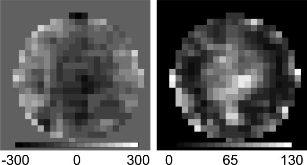
Figure 8 is an example of bandwidth error for subject 13. On the left is the average corrected wavefront and on the right is the standard deviation of each pixel over the series of wavefronts. This calculation can be completed for all subjects and based on the average standard deviation bandwidth error is 26 ± 12 nm rms. Using this method we are actually calculating the combination of measurement and bandwidth errors, however because measurement errors are small this will be dominated by bandwidth error. Most temporal variation occurs in the center of the wavefront and is largely low-order. As with measurement error there is variability between subjects making this error source potentially significant for system robustness as well.
Fig. 8.
Left: Average corrected wavefront for subject 13, colorbar is in nm. Right: Standard deviation of each pixel of the reconstructed wavefront across all converged wavefronts for subject 13, color bar is in nm rms. The average value over all subjects is 26 ± 12 nm rms.
The bandwidth can be estimated from the sampling rate to be around 1 Hz, but a more direct measurement is desirable. Currently when AO data are collected for a subject the archive only includes a few frames before the AO loop is turned on, making a comparison of temporal variation with and without AO difficult. We have modified our experimental practices to record more un-corrected data in order to quantify the bandwidth of our system. Not only would this be helpful for an overall error budget it would provide another metric for system variability. Perhaps some poor corrections are caused by changes in the errors introduced by limited bandwidth. Of course another potential limitation to a higher sampling rate is the decreased light level per sub-aperture per timestep. The improvement in wavefront correction caused by higher bandwidth must be balanced against the increase in wavefront error introduced by measurement errors caused by fewer photons.
Several studies have been conducted to determine the necessary system bandwidth for a vision science AO system [9, 8]. Hofer et al. suggest that bandwidth of between 1 and 2 Hz would be optimal, but note that even low-order errors have temporal variation at up to 5 Hz [9]. While Santana et al. estimate a measurable benefit at even higher bandwidths [8] . In both studies the pupil was not dilated, which could introduce more errors. These studies and our data suggest that increased bandwidth is desirable.
Not all bandwidth errors are derived from temporal variations in the eye. The AO sample arm scans the retina and while the double pass configuration should provide a stable pupil plane, the changes in the optical path caused by scanning can introduce wavefront error. With the model eye in place and holding the scanning mirrors at several positions we find that the difference in wavefront can easily be > 50 nm rms. As the scan rate is much faster than the AO sampling rate this is a source of temporal error, although the errors may average out. Alignment of the scan mirrors is critical, but may not be sufficient to controlling this source of error. Faster frame rates for the WFS may also help reveal errors introduced by scanning and hence make them more correctable.
3.4. Reconstructor error
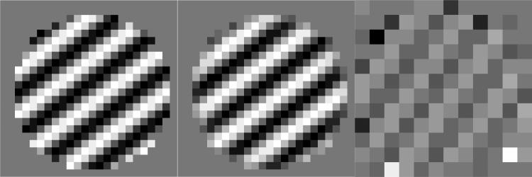
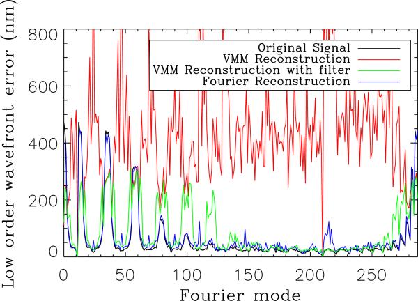
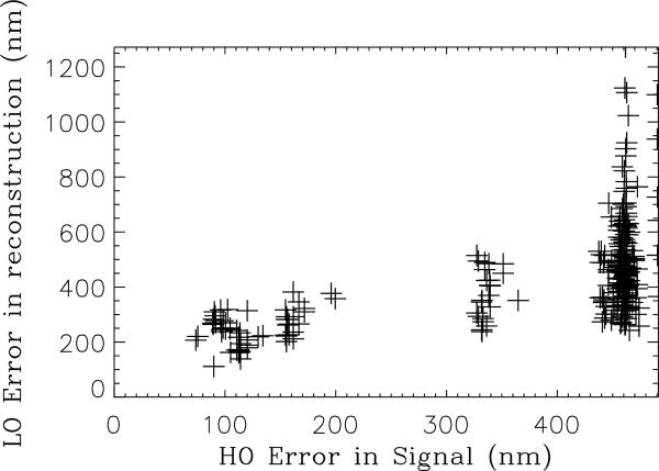
Since our WFS has 20 × 20 sub-apertures while the MEMS has only 12 × 12 the AO controller must down-sample from the WFS to the MEMS. In the VMM no filtering is used and this could lead to aliasing of high-spatial frequency errors that the WFS can measure but the MEMS cannot correct to low spatial frequencies where we expect better AO performance. This should not be confused with aliasing within the WFS, which cannot be measured and must be removed with a physical spatial filter [26]. In post processing the FTR uses all of the information from the WFS to reconstruct the wavefront and does not down-sample. To quantify the errors introduced by this aliasing we produced a series of wavefronts with varying amounts of error, calculated the WFS slopes from these wavefronts and then reconstructed them using either the FTR or the down-sampling VMM. Any series of wavefronts can be used, but in order to test the effect of higher spatial frequencies the wavefront must contain sufficient amounts of those errors. We attempted to use a series of Zernikes, but with 200 Zernike modes, very little power was produced in the spatial frequencies of interest. Fourier modes are an excellent tool for testing the spatial frequency response of a wavefront reconstructor because they can produce power at all spatial frequencies depending on the sampling of the wavefront. Figure 9 is an example of one individual Fourier mode used for testing [13]. Individual modes, while representative of the error, do not help us quantify the size of the reconstructor error. Instead it is useful to sum the low-order error produced from reconstructing each mode using the FTR or the VMM and compare that value to the low-order power in the original signal. In Fig. 10 we plot the rms error summed from 0 to 2 cycles per aperture for the two reconstructed signals and the original signal. The VMM consistently has more low-order error than the input signal. However, if the signal is filtered prior to reconstruction to remove the errors that the WFS can measure but the MEMS cannot correct then additional low-order error is not introduced by the VMM reconstruction (See green curve in Fig. 10). For this simulation the amount of high-order error introduced was arbitrary and quite large, which produced high values for the aliased low-order error. Figure 11 is a plot comparing the amount of high-order error introduced in the signal with the amount of low-order error in the reconstruction. Extrapolating from the lower values of high order error we expect approximately twice the amount of low-order error will be produced by the measured high-order error, about 60 nm rms in our case. This simulation, however because of the large high-order errors used is not ideal for predicting aliased error. Certainly this type of error is produced by the VMM controller, and rather than complete a more robust simulation we prefer to look into implementing an improved controller. Besides the magnitude of high-order error, low-order aliased error will be dependent on the spatial frequency of the input high order error (hence the scatter in Fig. 10).
Fig. 9.
A wavefront with a specific Fourier mode (left) was reconstructed using the Fourier reconstruction (middle) and the VMM reconstruction (right).
Fig. 10.
A series of Fourier modes was used to test the VMM and FTR. The rms error from 0 to 2 cycles per aperture is calculated for each mode for the original signal and the two reconstructions. The VMM consistently has more low-order error than the input signal, likely caused by aliasing in the down-sampling from the 20 × 20 WFS measurement to the 12 × 12 MEMS array. If the wavefront is filtered to remove high-order errors prior to reconstruction the VMM reconstructor does not introduce additional low-order error.
Fig. 11.
Low-order (LO) measured in the reconstructed VMM signal is plotted as a function of higher-order (HO) error measured in the input signal.
When using AO systems with over-sampled wavefront sensing one should consider how the particular control system handles higher spatial frequency errors. One way to investigate the error is to examine the frequency response of the controller as described here and there are several ways to correct this type of reconstructor error, if it is identified. In an instrument with matched WFS and deformable mirror this error should not be introduced. For a VMM type controller some kind of filtering is needed of the control matrix, while for the FTR all of the WFS information is used to reconstruct and the resulting wavefront can be filtered before it is down-sampled to apply to the deformable mirror.
3.5. Isoplanatic error
In a vision AO system, wavefront error is measured from a single point source traveling along a specific path through the eye. The isoplanatic patch indicates the angular extent over which the measured wavefront can be used without introducing more than a specified limit of WFE. The size of the isoplanatic patch of the eye has been investigated by several groups and a nice summary of the reported values can be found in Bedggood et al. [27] In general, the values range from 1 to 3 degrees. Outside of this region errors can become quite large. However, in the context of the error budget it is important to keep in mind that even within the isoplanatic patch anisoplanatism exists. The variation in patch size measured by different groups is in part because of different criteria used as the limiting WFE magnitude. One of the strictest criteria for isoplanatic angle is the Marechal criteria, which uses a cutoff of λ/14 for calculating the size of the patch [27]. At our wavelength of approximately 840 nm this indicates that within the isoplanatic patch 60 nm rms of wavefront error could be introduced by anisoplanatism. As in most vision systems the AO system is effectively measuring the average wavefront error over the scanned region, which may also affect the frequency content of the isoplanatic errors. Most of the error introduced by anisoplanatism should be measured by the WFS, so if there are unaccounted for errors in our final error budget anisoplanatism is a likely source. Anisoplanatism is difficult to reduce, but multi-conjugate adaptive optics shows promise [28, 29].
3.6. Calibration Error
A WFS measurement is a relative measurement of wavefront error because it is based on the reference the WFS uses. The calibration error is the error between the relative wavefront measured by the WFS and the actual wavefront error of the system. The current method for obtaining a WFS reference in our system is described in Section 2, but an independent means of measuring wavefront error is desirable. A CCD dedicated to measuring the PSF of the system is one way to measure calibration error. Logean et al. recently published work indicating the challenges in measuring a real-time double-pass PSF with a human subject [30], but measurements with a model eye should be much easier and still quantify calibration errors.
4. Error Budget Summary
An error budget can be a helpful tool for summarizing AO system characterization, or as a design tool for future systems because it allows all the constituent errors and their relative sizes to be listed. We have summarized our characterization in Table 1. The largest error remains the uncorrected low-order error that we attribute at least a portion of to aliasing within the control matrix. The real time AO controller must be changed to remove this type of error. Filtering of the control matrix may be sufficient, but we plan to implement FTR. Out of band and bandwidth errors are similarly sized, but the relative ease of increasing frame rate of the system compared to increasing the number of actuators suggests that this should be the next area for improvement. The error budget does not completely account for measured WFE in the system. The discrepancy is caused by un-accounted for errors, in particular anisoplanatism. Scatter off of optical elements in the system, including the MEMS, are also not included in the summary, but are not likely to affect performance for subjects with strong reflectivity. Calibration errors are not included in either the measured or calculated errors of the error budget.
Table 1.
Residual wavefront errors are summarized in an error budget. The largest error remains the uncorrected low-order error that we attribute at least in part to aliasing within the control matrix. Out of band and Bandwidth errors are also significant, but bandwidth should be easier to correct and is the highest priority for the AO-OCT system.
| Error | nm rms |
|---|---|
| Out of band | 33 ± 20 |
| MEMS precision | 12 |
| Measurement | 12 |
| Bandwidth | 26 ± 12 |
| Aliasing | 60 |
| Total Calculated | 75 |
| Total Measured | 95 |
5. Conclusions and recommendations for improved system performance
We have presented an updated error budget for our AO-OCT system and discussed how these constituent errors might be calculated for other systems. Correcting aliasing in the control matrix and increasing bandwidth are identified as the top priorities for improving system performance. Because of variations in reflected light from the retina between subjects measurement error varies and suggests that the single values for constituent errors in the error budget are not sufficient for understanding overall system performance, particularly robustness. We suggest that system robustness would be improved by monitoring and adapting the AO system for changing conditions. Currently the gain of the system is adjustable for the real-time controller, we suggest adding adjustable control of the system frame rate and the aperture size for improved system robustness. Real-time monitoring of total photons per sub-aperture would facilitate the user adjustments of bandwidth or aperture size.
Acknowledgements
The authors thank Lisa Poyneer for her helpful advice regarding errors in reconstruction and the Fourier Transform Reconstructor. This work performed under the auspices of the U.S. Department of Energy by Lawrence Livermore National Laboratory under Contract DE-AC52-07NA27344. This research was supported by the National Eye Institute (grant EY 014743). This work was supported by funding from the National Science Foundation. The Center for Biophotonics, an NSF Science and Technology Center, is managed by the University of California, Davis, under Cooperative Agreement No. PHY 0120999. LLNL-JRNL-411655.
References and links
- 1.Zawadzki R, Jones S, Olivier S, Zhao M, Bower B, Izatt J, Choi S, Laut S, Werner J. Adaptive-optics optical coherence tomography for high-resolution and high-speed 3D retinal in vivo imaging. Optics Express. 2005;13(21):8532–8546. doi: 10.1364/opex.13.008532. [DOI] [PMC free article] [PubMed] [Google Scholar]
- 2.Zawadzki R, Choi S, Fuller A, Evans J, Hamann B, Werner J. Cellular resolution volumetric in vivo retinal imaging with adaptive optics–optical coherence tomography. Opt. Express. 2009;17(5):4084–4094. doi: 10.1364/oe.17.004084. [DOI] [PMC free article] [PubMed] [Google Scholar]
- 3.Macintosh B, Graham J, Palmer D, Doyon R, Dunn J, Gavel D, Larkin J, Oppenheimer B, Saddlemyer L, Sivaramakrishnan A, et al. The Gemini planet imager: from science to design to construction. Proc. SPIE. 2008;7015:7015–43. [Google Scholar]
- 4.van Dam M, Le Mignant D, Macintosh B. Performance of the Keck Observatory Adaptive-Optics System. Appl. Opt. 2004;43(29):5458–5467. doi: 10.1364/ao.43.005458. [DOI] [PubMed] [Google Scholar]
- 5.Evans JW, Macintosh BA, Poyneer L, Morzinski K, Severson S, Dillon D, Gavel D, Reza L. Demonstrating sub-nm closed loop MEMS flattening. Opt. Express. 2006;14:5558–5570. doi: 10.1364/oe.14.005558. [DOI] [PubMed] [Google Scholar]
- 6.Devaney N, Dalimier E, Farrell T, Coburn D, Mackey R, Mackey D, Laurent F, Daly E, Dainty C. Correction of ocular and atmospheric wavefronts: a comparison of the performance of various deformable mirrors. Appl. Opt. 2008;47(35):6550–6562. doi: 10.1364/ao.47.006550. [DOI] [PubMed] [Google Scholar]
- 7.Fernandez E, Vabre L, Hermann B, Unterhuber A, Povazay B, Drexler W. Adaptive optics with a magnetic deformable mirror: applications in the human eye. Opt. Express. 2006;14(20):8900–8917. doi: 10.1364/oe.14.008900. [DOI] [PubMed] [Google Scholar]
- 8.Diaz-Santana L, Torti C, Munro I, Gasson P, Dainty C. Benefit of higher closed–loop bandwidths in ocular adaptive optics. Opt. Express. 2003;11(20):2597–2605. doi: 10.1364/oe.11.002597. [DOI] [PubMed] [Google Scholar]
- 9.Hofer H, Artal P, Singer B, Aragón J, Williams D. Dynamics of the eyes wave aberration. J. Opt. Soc. Am. A. 2001;18(3):497–506. doi: 10.1364/josaa.18.000497. [DOI] [PubMed] [Google Scholar]
- 10.Zawadzki R, Choi S, Jones S, Oliver S, Werner J. Adaptive optics-optical coherence tomography: optimizing visualization of microscopic retinal structures in three dimensions. J. Opt. Soc. Am. A. 2007;24(5):1373–1383. doi: 10.1364/josaa.24.001373. [DOI] [PMC free article] [PubMed] [Google Scholar]
- 11.Horsley DA, Park H, Laut JS, Sophie P, Werner Characterization of a bimorph deformable mirror using stroboscopic phase-shifting interferometry. Sens. Act. A: Physical. 2007;134:221–230. doi: 10.1016/j.sna.2006.04.052. [DOI] [PMC free article] [PubMed] [Google Scholar]
- 12.Bifano T, Bierden P, Perreault J. Gonglewski JD, Gruineisen MT, Giles MK, editors. “Micromachined Deformable Mirrors for Dynamic Wavefront Control,” in Advanced Wavefront Control: Methods, Devices and Applications II. Proc. SPIE. 2004;5553:1–16. [Google Scholar]
- 13.Evans J, Zawadzki R, Jones S, Okpodu S, Olivier S, Werner J. Performance of a MEMS-based AO-OCT system. Proceedings of SPIE. 2008;6888:68880G. SPIE. [Google Scholar]
- 14.Chen D, Jones S, Silva D, Olivier S. High-resolution adaptive optics scanning laser ophthalmoscope with dual deformable mirrors. J. Opt. Soc. Am. A. 2007;24(5):1305–1312. doi: 10.1364/josaa.24.001305. [DOI] [PubMed] [Google Scholar]
- 15.Poyneer L, Gavel D, Brase J. Fast wave-front reconstruction in large adaptive optics systems with use of the Fourier transform. J. Opt. Soc. Am. A. 2002;19(10):2100–2111. doi: 10.1364/josaa.19.002100. [DOI] [PubMed] [Google Scholar]
- 16.Poyneer L, Véran J. Optimal modal Fourier-transform wavefront control. J. Opt. Soc. Am. A. 2005;22(8):1515–1526. doi: 10.1364/josaa.22.001515. [DOI] [PubMed] [Google Scholar]
- 17.Poyneer LA, Macintosh B. Experimental demonstration of phase correction with a 32 × 32 microelectricalmechanical systems mirror and a spatially filtered wavefront sensor. J. Opt. Soc. Am. A. 2004;21:810–819. doi: 10.1364/ol.31.000293. [DOI] [PubMed] [Google Scholar]
- 18.Poyneer L, Dillon D, Thomas S, Macintosh B. Laboratory demonstration of accurate and efficient nanometer-level wavefront control for extreme adaptive optics. Appl. Opt. 2008;47(9):1317–1326. doi: 10.1364/ao.47.001317. [DOI] [PubMed] [Google Scholar]
- 19.Evans JW, Zawadzki RJ, Jones S, Olivier S, Werner JS. Performance of a MEMS-based AO-OCT system using Fourier reconstruction. MEMS Adaptive Optics III [Google Scholar]
- 20.Roberts L, Jr, Perrin M, Marchis F, Sivaramakrishnan A, Makidon R, Christou J, Macintosh B, Poyneer L, van Dam M, Troy M. Is that really your Strehl ratio? Proceedings of SPIE. 2004;5490:504. [Google Scholar]
- 21.Porter J, Guirao A, Cox I, Williams D. Monochromatic aberrations of the human eye in a large population. J. Opt. Soc. Am. A. 2001;18(8):1793–1803. doi: 10.1364/josaa.18.001793. [DOI] [PubMed] [Google Scholar]
- 22.Francisco Castejón-Mochón J, Lopez-Gil N, Benito A, Artal P. Ocular wave-front aberration statistics in a normal young population. Vision Research. 2002;42(13):1611–1617. doi: 10.1016/s0042-6989(02)00085-8. [DOI] [PubMed] [Google Scholar]
- 23.Nicolle M, Fusco T, Rousset G, Michau V. Improvement of Shack-Hartmann wave-front sensor measurement for extreme adaptive optics. Opt. Lett. 2004;29(23):2743–2745. doi: 10.1364/ol.29.002743. [DOI] [PubMed] [Google Scholar]
- 24.Prieto P, Vargas-Martín F, Goelz S, Artal P. Analysis of the performance of the Hartmann-Shack sensor in the human eye. J. Opt. Soc. Am. A. 2000;17(8):1388–1398. doi: 10.1364/josaa.17.001388. [DOI] [PubMed] [Google Scholar]
- 25.Baker K, Moallem M. Iteratively weighted centroiding for Shack-Hartmann wave-front sensors. Opt. Express. 2007;15(8):5147–5159. doi: 10.1364/oe.15.005147. [DOI] [PubMed] [Google Scholar]
- 26.Poyneer LA, Bauman B, Macintosh BA, Dillon D, Severson S. Spatially filtered wave-front sensor for high-order adaptive optics. Opt. Lett. 2006;31:293–295. doi: 10.1364/ol.31.000293. [DOI] [PubMed] [Google Scholar]
- 27.Bedggood P, Daaboul M, Ashman R, Smith G, Metha A. Characteristics of the human isoplanatic patch and implications for adaptive optics retinal imaging. J. Biomed. Opt. 2008;13:024, 008. doi: 10.1117/1.2907211. [DOI] [PubMed] [Google Scholar]
- 28.Bedggood P, Ashman R, Smith G, Metha A. Multiconjugate adaptive optics applied to an anatomically accurate human eye model. Opt. Express. 2006;14(18):8019–8030. doi: 10.1364/oe.14.008019. [DOI] [PubMed] [Google Scholar]
- 29.Dubinin A. Human retina imaging: widening of high resolution area. J. Modern Opt. 2008;55(4):671–681. [Google Scholar]
- 30.Logean E, Dalimier E, Dainty C. Measured double-pass intensity point-spread function after adaptive optics correction of ocular aberrations. Opt. Express. 2008;16(22):348–357. doi: 10.1364/oe.16.017348. [DOI] [PubMed] [Google Scholar]


