Abstract
In this study, we demonstrate a facile and simple synthesis of quantum dot (QD)–polymer composites. Highly fluorescent semiconducting CdSe/ZnS quantum dots were embedded in different commercially available polymers using one easy step. QD–polymer composite nanoparticles were also synthesized using template-assisted synthesis. In particular, we self-assembled lamellar micelles inside nanoporous alumina membranes which were used for the synthesis of mesoporous silica hollow nanotubes and solid nanorods. We observed that the addition of excess free octadecylamine (ODA) in the QD–silica solution resulted in gelation. The gelation time was found to be dependent on free ODA concentration. Similarly, the emission of QD–polymer composites was also found to be dependent on free ODA concentration. Highly purified QDs provided polymer composites that have a much lower emission compared to unpurified nanocomposites. This was attributed to passivation of the QD surfaces by amine, which reduced the surface defects and non-radiative pathways for excited QDs. Finally, highly fluorescent QD–polymer patterns were demonstrated on glass substrates which retained their emission in both polar and non-polar solvents.
Introduction
Colloidal semiconductor QDs are ideal fluorescent nanoparticles.1–7 The emission properties of these QDs can be easily tuned through their particle size, shape and chemical composition. QDs with different particle sizes can be excited with a single excitation source, making them a very powerful imaging tool.1 QDs are also more photostable than organic fluorescent dyes. Due to their unique optical and electronic properties, QDs have found applications in a wide range of fields including biosensing, 2,8b–f bioanalysis,8a imaging probes,9 viral capsids,10 multicolor imaging,11 QD-based lasers,12 light emitting devices (LEDs)13 and photovoltaic cells.14–16 Furthermore, strong coulomb coupling between charge carriers was found to generate multi-excitons by a single photon via carrier (or exciton) multiplication. 17 Multiple exciton generation can significantly increase the photovoltaic energy conversion efficiency.
In general, coatings on CdSe QDs with higher band gap materials, such as ZnS shells, increase the photostability and luminescence properties of the resulting core-shell QDs.5 The shell creates a more passivated surface leading to a decrease in the non-radiative pathways and effectively increasing quantum yield (Qy) and the photostability of QDs. QDs synthesized using a high temperature procedure generally have a hydrophobic surfactant coating4–7 on their surface, which must be changed to a hydrophilic coating for uses in bio-related applications. This is usually performed through ligand exchange,2,3,19 sol-gel chemistry20 and micelle coating.21 Some of these surface modifications are found to reduce the quantum efficiency and emission lifetime of QDs.22 Another way to change the surface properties of QDs is to encapsulate them in polymers and proteins,23 cross-linked micelles,24 polymer beads25 and clay–polymer nanocomposites.26 These treatments usually protect the QDs and sometimes have been shown to enhance their emission properties. In this study, we investigate the encapsulation of CdSe/ZnS core-shell QDs in different commercially available polymer matrices such as silica, silicone, cyanoacrylate and epoxy. We have found that the encapsulation of QDs in some polymers resulted in either a loss or a gain in the emission. These results were attributed to the presence of free ODA in the solution. We investigated the mechanism of gelation of a QD–silica composite, which was observed when a QD solution was mixed with a silica-precursor solution. We also found that the amount of chloroform in the QD–silica solution played a key role in determining whether hollow nanotubes or solid nanorods would be formed in the solution. This is because the addition of chloroform significantly increases the local critical micelle concentration (CMC) of the surfactant that leads to a decrease in the surfactant–silica micelle thickness along the nanopore walls. This resulted in the formation of hollow silica nanotubes. Finally, we demonstrate the patterning of highly fluorescent QD–polymer composites on glass substrates which retained their emission in different experimental environments.
Experimental
Chemicals and materials
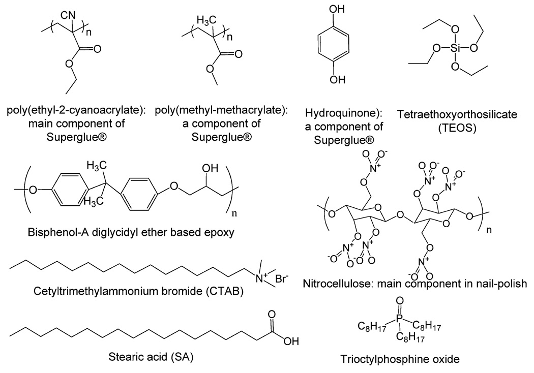
Selenium powder (Se), cadmium oxide (CdO), octadecylamine (ODA), stearic acid, and zinc stearate (Zn(SA)2) were purchased from Acros Organics. Tri-n-octylphosphine oxide (>90%) (TOPO), sulfur (S), chloroform and methanol were purchased from Sigma Aldrich and a sample of trioctylphosphine was kindly donated by Cytech Industry. All the chemicals were used as received, without any further purification. We used commercially available polymers, such as Super Glue®, 2-part epoxy and silicone polymers for the synthesis of QD composites. Super Glue® (product number 15187, Pacer Technology) is a commercially available cross-linkable polymer based on ethyl-2-cyanoacrylate, poly(methyl methacrylate) and hydroquinone. 5-Minutes Epoxy® (catalogue number 20945) was obtained from ITW Devcon. Its base is a bisphenol-A diglycidyl ether resin with polymercaptan amines. GE Silicone II® (GE 5000) is a silicone polymer that cross-links through a condensation reaction. We chose these polymers because they are commercially available, inexpensive, and their physical properties range from very hard (cyanoacrylate and epoxy) to very soft (silicone). The chemical structures of the polymer matrices and their chemistry are provided in Scheme 1 and Scheme 1S (ESI†) respectively.
Scheme 1.
Chemical structures of the different molecules used in these studies.
Synthesis of CdSe QDs
The synthesis of CdSe QDs was performed using a procedure similar to that of a previously published paper.27 A typical synthesis used in our research is as follows: CdO 13 mg, stearic acid 0.150 g, tri-n-octylphosphine oxide 2.00 g and octadecylamine 2.00 g were combined in a two neck 100 mL round bottom flask. The flask, equipped with a condenser, was sealed and placed under a continuous flow of argon. The flask was heated to 300 °C and rapidly stirred until the reddish-brown liquid became optically clear with a pale yellow color. At this time, a solution containing Se powder (79 mg) completely dissolved in trioctylphosphine (1 mL) was swiftly injected into the flask at ~300 °C. Immediately following the injection, samples were extracted at intervals of 5–10 seconds. Each individual sample was placed in a test tube and allowed to cool to 25 °C. Approximately 1 mL of chloroform was added to each test tube to saturate the QDs from a dried solid state to a muddy liquid state. Next the test tubes were filled with methanol (~5mL) and shaken vigorously to remove as much excess amine and TOPO as possible from the solution. Test tubes containing the QDs, ethanol, and chloroform were centrifuged at about 1500 rpm for 5 minutes. The hydrophobic QDs were precipitated out as pellets at the bottom of the test tubes, and the rest of the solution containing the excess amine, TOPO, ethanol and chloroform was decanted off. The QD precipitant was dispersed into 2–3 mL of fresh chloroform. This step is called purification step 1. In some cases, multiple purification steps were performed using the same procedure as described above.
Synthesis of CdSe/ZnS QDs
The encapsulation of the CdSe QDs with a ZnS coating was prepared using a previously published procedure:22 30–50 mg of previously synthesized CdSe QDs were dried and placed into a 150 mL round bottom flask. Octadecylamine (2.00 g), zinc stearate (0.200 g) and trioctylphosphine (2.0 mL) were heated to 150–180 °C in the round bottom flask equipped with a condenser under continuous argon flow. To this clear solution, 0.100 g of sulfur dissolved in octadecylamine (2.00 g) was added to the previously described mixture. The flask was resealed and kept at 150–180 °C under argon for approximately one hour. At the end of this time period, the flask was cooled to room temperature where 1 mL portions of the core-shell QDs were removed and placed in separate centrifuge tubes. These tubes were then filled with ethanol and the QDs were centrifuged at 1500 rpm for 5 minutes. The ethanol was extracted and the precipitant was dispersed with chloroform.
Synthesis of QDs containing silica nanorods
The silica precursor solution was synthesized using a previously published procedure,30c that we modified as follows: ethanol (7.70 g), tetraethoxyorthosilicate (TEOS, 11.61 g) and hydrochloric acid (HCl) (1 mL of 2.8 mM) were stirred vigorously in a 25 mL beaker. At the same time, ethanol (15 g), HCl (4 ml of 55 mM) and cetyltrimethylammonium bromide (CTAB, 1.50 g) were mixed together in a separate beaker until all the CTAB was dissolved. The CTAB solution was combined with the TEOS solution and continually stirred for 30 minutes. The CTAB/TEOS solution (250 µL) was added to a test tube consisting of CdSe/ZnS QDs (optical density (OD) at 400 nm ~0.6) in chloroform solvent. The solution was then poured onto a Whatman Anodisc® (200–300 nm pore diameter) drop wise under moderate vacuum filtration. The top and bottom surfaces of the Anodisc® templates were scraped using a razor blade, and allowed to dry overnight. The dissolution of templates to liberate nanoparticles was accomplished by soaking the templates in 1M NaOH or 10% phosphoric acid solution. The nanoparticles were captured through filtration on a nanoporous alumina filter with 20 nm pore diameter.
QD encapsulation in commercially available polymers
We have encapsulated QDs in different commercially available polymers using a simple one-step synthetic route. Our first attempt to encapsulate QDs into commercial grade Dow Corning Sylgard 184® silicone polymer was however not successful, because of the presence of free ODA, Se and S in the QD solution which inhibited the cross-linking reactions by complexation with a platinum catalyst (this process is called catalyst poisoning).31 However, the QDs were successfully encapsulated in a one-part condensation cured silicone polymer GE 5000®. The curing mechanisms of Sylgard 184® and GE 5000® are quite different. Sylgard 184® uses a Pt catalyst for cross-linking whereas GE 5000® cross-links through a condensation mechanism. GE 5000® does not employ a metal catalyst for curing (see Scheme S1 (ESI†) for more details) and is thus not affected by the presence of amine, S, and Se. A typical procedure used in the study for encapsulation is as follows: CdSe/ZnS QDs (20–30 mg) were dispersed in 5 mL chloroform and placed into a 25 mL beaker. A commercial silicone sealant (2.5 g, GE 5000®) was dispensed through a caulking gun into the beaker containing the QDs in chloroform. The beaker was equipped with a stir bar and the solution was stirred until all the silicone was dissolved. Using a pipette, the solution was filtered through an alumina membrane (Anodisc® from Whatman, pore diameter 20 nm). QDs containing alumina discs were allowed to dry for approximately 30 minutes and were allowed to cure for several hours. The release of QD–silicone nanoparticles from the alumina template and their capture on a nanoporous alumina filter were performed as described earlier (see above).
QDs were also encapsulated into two other commercially available polymers: cyanoacrylate and two-part epoxy. In a typical procedure used in this study, 2 mL of QDs dissolved in a chloroform solution (OD = 0.5) was mixed vigorously with 2 mL of a polymer solution at room temperature. The curing of the composites was performed at room temperature for several hours.
Highly fluorescent QD–polymer patterning
The patterning of the QD–polymer mixture on flat surfaces (such as glass slides) was performed by squeezing the QD–polymer composite mixture out of a nozzle or a pipette. All the patterns were performed manually at room temperature. The composite patterns prepared from QDs and polymers (cyanoacrylate, epoxy, and silicone) were highly fluorescent, and their emission was stable for up to several days without any significantly diminished emission properties.
Characterization of QDs and QD–polymer nanocomposites
The CdSe/ZnS QDs were characterized using UV-Vis and emission spectroscopies, and scanning (SEM) and transmission electron (TEM) microscopies. QDs were characterized using a Perkin-Elmer Lambda 25 UV/VIS spectrometer with the following parameters: slit width was 1 nm and scan speed 480 nm/min. The emission spectrum of QDs was performed on a Perkin-Elmer LS 55 spectrometer (λex = 400 nm, scan speed: 500 nm/min, and slit width 10 nm). With the use of known organic dyes as standards,28 Qy of the QDs can be determined using the following equation:29
| (1) |
where “QD” represents quantum dots and “s” the standard used. Table 1 lists the Qy of the synthesized QDs and Table 1S (ESI†) shows Qy of the standard used in our experiments.
Table 1.
Estimated Qy of quantum dots synthesized in the present study
| Emission Color | ||||||
|---|---|---|---|---|---|---|
| Green Emitting |
Yellow Emitting |
Red Emitting | ||||
| Quantum Dots | λem | Φem | λem | Φem | λem | Φem |
| CdSe | 534 nm | 5% | 572 nm | 3% | 622 nm | 2% |
| CdSe/ZnS | 534 nm | 75% | 565 nm | 61% | 617 nm | 47% |
SEM and TEM analyses were performed on a Hitachi 570 and a Hitachi 7100 respectively. For SEM analysis, the released QD–polymer nanoparticles from templates were collected on a nanoporous alumina template. Then, a thin sputtered layer (5–10 nm in thickness) of gold-palladium alloy was applied to QDs embedded in the polymers to increase the electrical conductivity of the samples for SEM analysis. TEM samples were prepared by touching TEM grids onto the surface of a drop containing nanoparticles.
Results and discussion
Synthesis and characterization of QDs
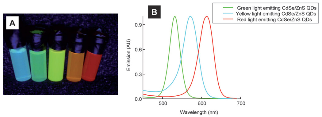
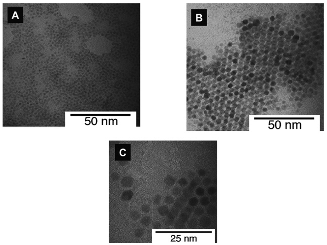
QDs used in the present study were synthesized using low cost readily available starting chemicals. Fig. 1A shows an optical photograph of CdSe/ZnS core-shell QDs dispersed in chloroform following excitation at 365 nm. We synthesized QDs that emit photons ranging from bluish-green to the red color region. Typical emission and electronic absorption spectra of as-synthesized green, orange and red emitting QDs are shown in Fig. 1B and Fig. 1S (ESI†) respectively. The full-width-at-half-maxima (FWHM) of the emission spectra of QDs were ~30–40 nm. Following the addition of a ZnS shell on CdSe core QDs, there was an increase in both Qy and size of the QDs. Fig. 2 shows TEMs of CdSe/ZnS QDs of three different diameters. Tables 1 and 1S (ESI†) list Qy of different CdSe and CdSe/ZnS QDs synthesized in this study and their corresponding organic standard used for Qy estimation. Qy values for different QDs were found to increase by >10–15 times after coating the CdSe QDs with a larger band gap ZnS coating. Assuming one ZnS monolayer is about ~0.31 nm thick,35 we estimate that there were roughly 5–6 ZnS monolayers on green light emitting CdSe core QDs.
Fig. 1.
Optical photographs (A) and corresponding emission spectra (B) of CdSe/ZnS core-shell QDs. See main text for details.
Fig. 2.
TEM images of (A) green; (B) yellow; and (C) orange light emitting CdSe/ZnS core-shell QDs. An accelerating voltage of 200 kV was used for these experiments.
Synthesis and characterization of QD–silica composites
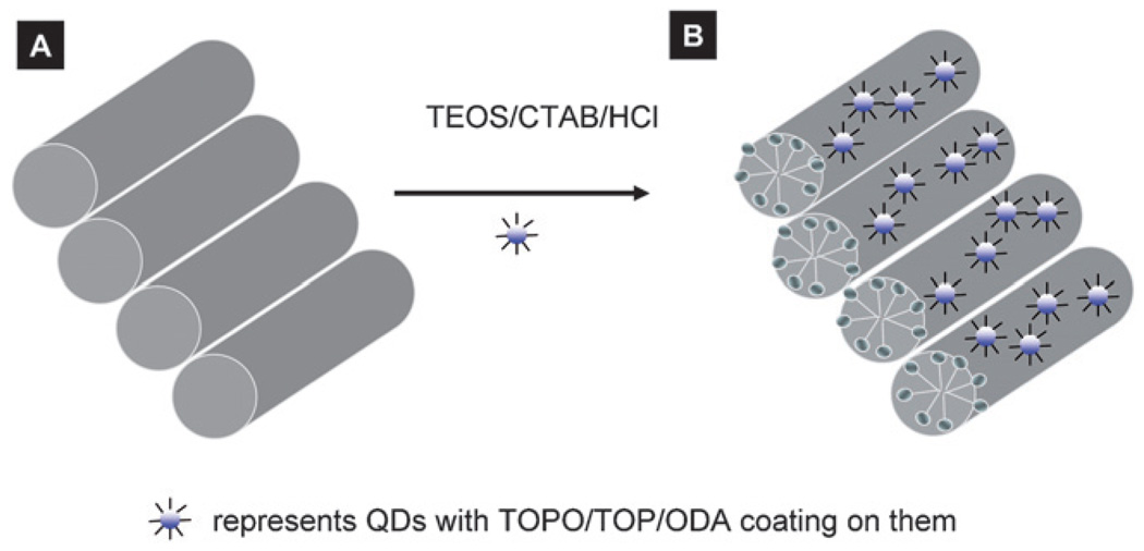
QDs embedded in silica nanoparticles were synthesized using a template-assisted method which is a very convenient and simple way for the synthesis of large quantities of monodispersed nanoparticle.30a,b Another way to synthesize nanoparticles is to use molecular templates which can self-assemble into different nanostructures and can act as templates for nanomaterials synthesis. Depending upon the choice of molecular templates used, the mesostructures can be easily tuned from isotropic-hexagonal phase to large multilamellar phase.32c,d Recently, Yamaguchi et al.30c demonstrated that lamellar micelle-based silica synthesis yielded mesoporous silica nanorods inside a nanoporous alumina membrane. The authors showed that the solid mesoporous silica channels (of 3.4 nm diameter nanochannels) were parallel to the alumina nanopores. In this study, we used a procedure similar to that of Yamaguchi et al.30c for the synthesis of QD–silica solid nanoparticles inside a nanoporous alumina membrane (Scheme 2). First, CTAB was self-assembled into hexagonal packed liquid crystalline lamellar micelles inside alumina nanopores (Scheme 2A).30c This self-assembly starts at the walls of the pores and propagates into the rest of the space inside the alumina pores. The alumina nanopores help one-directional, self-assembly growth of micelles along the nanopore direction.30c,33 Since the micelles are positively charged, the silica polymerization initiated at the outer surface of the micelles resulted in mesoporous nanoparticles inside the template (Scheme 2B).
Scheme 2.
Schematic of encapsulation of QDs in silica nanoparticles
Under our experimental conditions, we observed two interesting phenomena which were not reported by Teramae’s group.30c First, we found that when QDs in chloroform was mixed with a silica-precursor solution, rapid gelation of a silica–QD mixture was observed at room temperature (see videos in the ESI†). Second, whereas Teramae’s group only observed solid nanorods in their experiments, we found the presence of both hollow silica nanotubes and solid nanorods in our experiments. We now explain our observations in the following paragraphs.
Rapid gelation of QD–silica nanocomposites
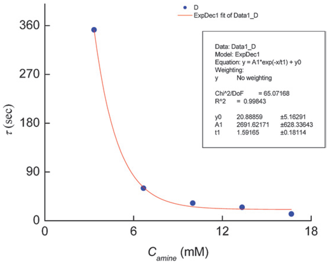
Mixing of QD solution in chloroform and silica precursor solution resulted in very fast gelation. The excess free amine (ODA) present in the QD solution appeared to facilitate the gelation. To investigate the QD–silica gelation process and the effect of free ODA on gelation time, we performed control experiments where a known amount of free ODA was added to the silica precursor solution at room temperature. The gelation time was then measured as a function of concentration of free ODA (Camine) in the solution. The gelation time is defined as the time it took for the solution in a test tube to become so viscous that it would not pour out of the test tube. Fig. 3 shows that with an increase in Camine, there was an exponential decrease in the gelation time. In fact, gelation time was reduced by almost thirty times when Camine was increased five-fold (Fig. 3). In the absence of ODA, however, the silica gelation was not observed for more than 60 minutes. Since primary amine is a weak base, it can significantly enhance the rate of hydrolysis of TEOS when present in excess in the solution. Thus, with an excess ODA present in the solution, there was a large increase in the rate of TEOS hydrolysis which contributed to rapid silica gelation. Moreover, a bilayer (first layer of TOPO/ODA and a second layer of CTAB) on the surface of QDs can also be formed in the presence of excess ODA.34 These hydrophobic bilayers on the QD surface can act as templates for the mesostructures around which silica can form three-dimensional structures. We believe that the enhanced TEOS hydrolysis rate and bilayer formation on the QD surface contributed to the fast gelation of silica inside the alumina template.
Fig. 3.
Gelation time (τ) versus free ODA concentration (Camine) for CTAB containing silica-precursor mixture.
Solid and hollow QD–silica nanoparticles
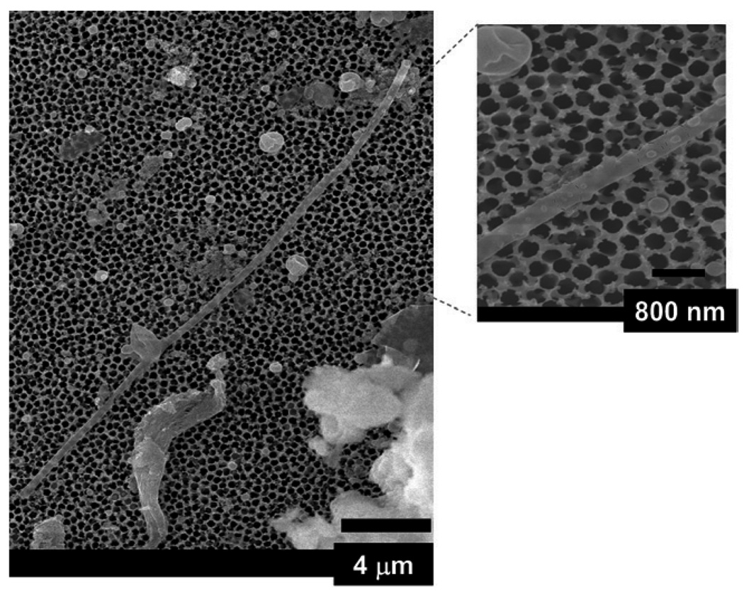
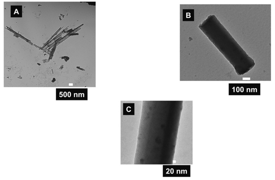
Interestingly, our electron microscopy data showed that the template-assisted QD–silica cylindrical nanoparticles consisted of a mixture of solid nanorods and hollow nanotubes with different wall thicknesses (Fig. 4 and Fig 5). The wall thickness of the silica hollow nanotubes was between 5 nm and 20 nm (Fig. 5A). An SEM image of a hollow silica nanotube of ~25 µmin length is shown in Fig. 4. The nanotube was most likely longer than 25 µm but it was broken during dissolution of the template and its collection on the alumina nanoporous filter. We concluded that the nanotube was hollow because the probing electron beam had partially penetrated through the nanotube and that some features of the alumina filter on which the nanotubes were collected can be seen in the micrograph. This would not occur if the nanotube were solid, because the electron beam (with 20 kV energy) would not have passed through a diameter of more than 200 nm of a solid silica nanorod. Moreover, we observed many solid silica nanorods in our TEM (Fig. 5B and C). Teramae’s group only found ~20 microns long solid silica nanorods in their experiments.30c We used a synthetic procedure similar to that of Yamaguchi et. al.30c except with the addition of QDs dissolved in chloroform. We were surprised to observe the presence of hollow QD–silica nanotubes in addition to solid nanorods in our experiments (Fig. 4 and Fig 5). We attribute the formation of hollow QD–silica nanotubes to the presence of low dielectric constant solvent in the synthetic solution. The overall free energy of the micelle formation is negative above the critical micelle concentration (CMC) of a surfactant in a given solvent.36 However, changing the solvent composition to a lower dielectric constant value decreases both the effectiveness of the chemical dipole of the surfactant and the charge separation ability of the resulting solvent such that the exchange energy of placing a free surfactant into micelle would be less thermodynamically favorable.36 In our case, the silica-precursor solution was prepared in a relatively high dielectric constant ethanol (dielectric constant, ε = 24.3 at 25 °C)37. After the addition of QDs in chloroform (ε = 4.8 at 20 °C)37, the dielectric constant of the resulting solution was decreased. Overall, the effect of the addition of a lower dielectric constant solvent in the solution was to increase in the CMC value of CTAB for the micelle formation which effectively shifted the micelle-free surfactant equilibrium towards the free surfactant side.36 This resulted in the destruction of some micelles in the alumina nanopores, and it favored the formation of some hollow nanotubes. It is not clear at this point if a given nanopore contains both solid nanorods and hollow nanotubes. In principle, the nanostructures with both hollow and solid features are possible if the local dielectric constant of the solution in a given nanopore is significantly different. For example, if a portion of the nanopore has a lower dielectric constant such that the CMC is larger than the local surfactant concentration, then we expect hollow nanotubes for this nanotube portion; whereas another part of the same nanoparticle with a higher dielectric constant could form a solid nanorod. Thus, controlling the local dielectric constant of the solution in the nanopores provides a convenient way to synthesize nanoparticles of novel structures.
Fig. 4.
A typical SEM of a hollow QD–silica nanotube synthesized using CTAB, silica precursor and QD solution. The length of the hollow nanotubes is about 25 µm. The inset SEM shows the dot nanostructures which may be composed of QDs-silica (see text for more details).
Fig. 5.
TEM images of hollow QD–silica nanotubes (A), and solid nanorods (B) and (C). The dark dots in (C) are due to the presence of QDs embedded in the nanoparticles.
Using a higher magnification of SEM analysis, we also observed uncharacteristic round dots on the nanotube’s surface (dotted circles in the electron micrograph, inset of Fig. 4). The exact nature of these dots is not entirely clear from the SEM image . It is possible that these dots could be silica coated QDs. The dark spots in the nanorods in our TEM are attributed to the presence of high electron density of elements (such as Cd, Se, and S). The dimension of these dark spots suggests that there are about one to five CdSe/ZnS QDs present in the QD–silica composites. QDs aggregation in the nanorods also contributed to the emission quenching of the resulting QD–silica nanoparticles (vide infra). We performed energy X-ray dispersive spectroscopic (EDS) analysis on our samples several times (four different times) on the QD-embedded nanoparticles. The signals from the aluminium sample holder and carbon tape (used to stick the sample on the sample holder) overwhelmed the signal from the sample. In spite of significantly increasing the QD concentration in the nanoparticles, the signal from QDs remained below the background signal. We would like to emphasize that for these samples, we could visibly see with our naked eye the emission and color from QDs but the signal at the detector was saturated with aluminium sample holder and carbon tape.
Emission of QD–silica composites
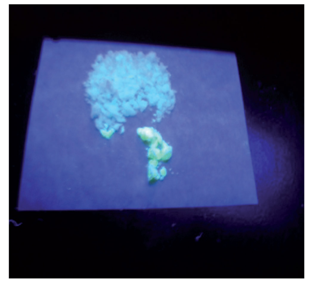
The emission of the QD–silica composite was found to decrease significantly following its encapsulation in silica. Fig. 6 shows the emission optical photograph of powdered QD–silica nanocomposite after the dissolution of alumina template in phosphoric acid. The nanocomposite was excited at a wavelength of 365 nm with a hand-held UV lamp. The quenching of emission was found to be dependent on the extent of purification of QDs used for the preparation of the composites. The emission of highly pure QDs containing composites were much lower (50–70%) than those of as-prepared composites. The purification ofQDs was performed by precipitating the as-prepared QDs with a large amount of ethanol followed by the centrifuging at high speed. This process resulted in a pallet of QDs, which was resuspended in chloroform. This step is called purification step 1. In general, we used QDs for encapsulation in polymers that were purified for ~2–3 steps.
Fig. 6.
The photograph of silica nanoparticles containing green CdSe/ZnS QDs when excited by a hand-held UV lamp (λexcitation = 365 nm). The silica nanotubes/nanorods embedded in the alumina templates were collected on a filter after dissolving the alumina template in phosphoric acid.
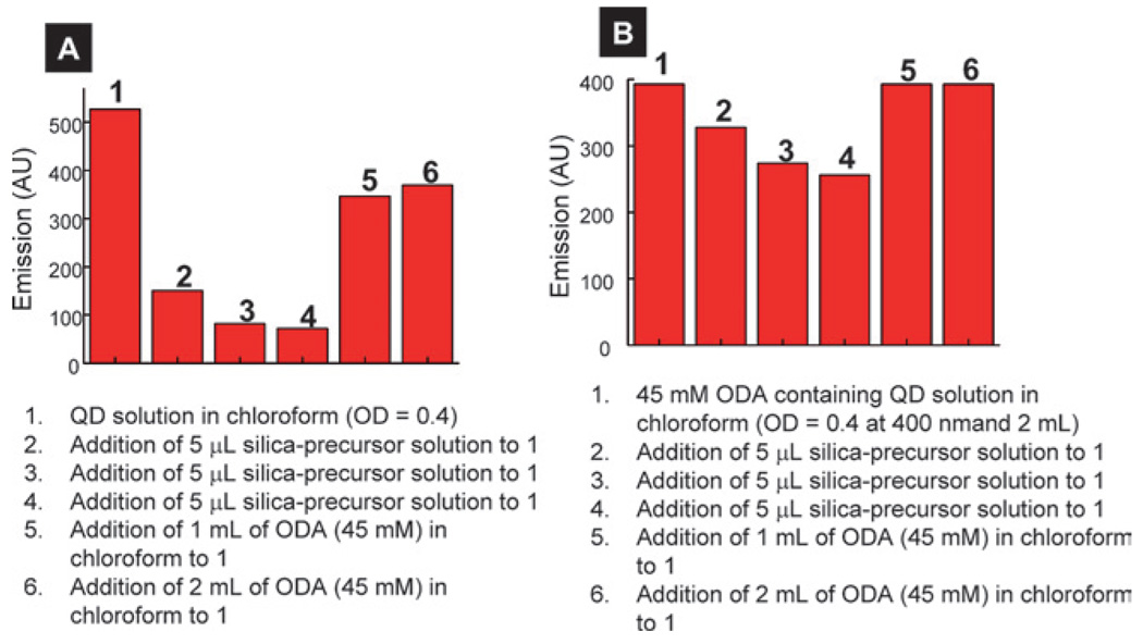
The purification steps significantly reduced the concentration of free ODA in the solution. It is known that the emission of QDs reduces significantly following their purification which is attributed to surface ligand loss, increase in surface defects, and/or loss of smaller QDs from the solution during purification.39 Further evidence that free ODA plays a critical role in QD emission came from two control experiments. First, the emission of the silica-precursor containing QD solution (OD = 0.4) was recovered to ~70% of its original emission value when an excess of amine was added to the solution (Fig. 7A). Second, the quenching of emission of QD solution with an excess of ODA following the addition of silica-precursor solution was significantly lower than a similar QD solution but without ODA in the solution. The emission of the latter solution recovered completely after the addition of excess ODA (Fig. 7B) which resulted in the reduction or elimination of non-emissive surface states or non-radiative pathways produced by ligand loss.39 These experiments clearly show that free ODA in the solution retarded the emission quenching of QDs. These results are in agreement with a recent report where the authors have found that an excess of amine in the solution showed enhanced emission as compared to solutions without amine.39
Fig. 7.
Effect of addition of silica precursor on the QD emission intensity to purified (A) and excess ODA containing (B) QD solution. All the solutions were excited at 400 nm.
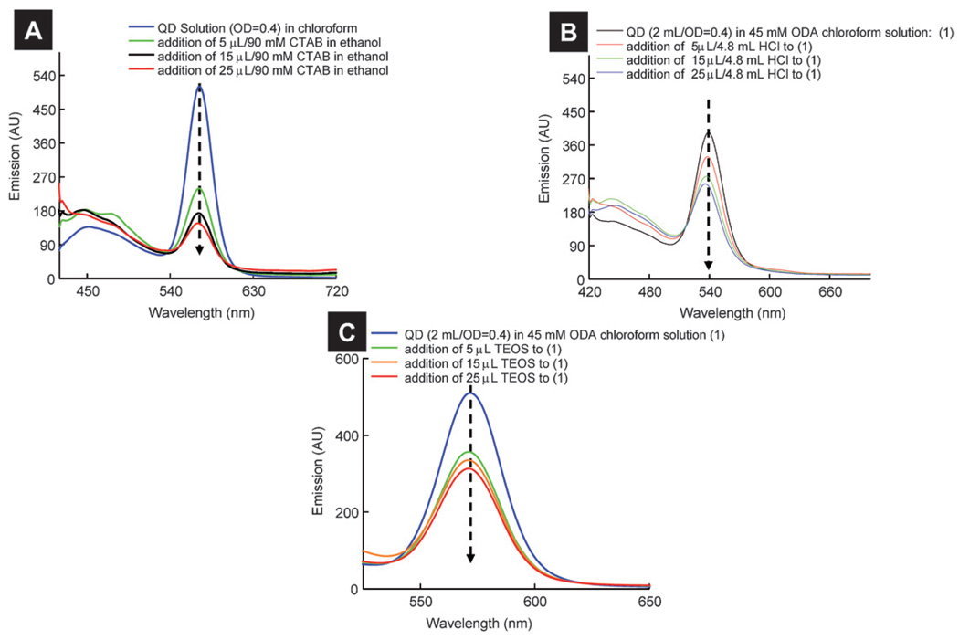
Since the silica precursor consisted of many components that can affect the emission of QD solution, it is not known which chemical components in the silica precursor contributed to emission quenching. To investigate the effect of the addition of different components present in the silica precursor to QD solution, we performed experiments where different components of the silica precursor were added to a QD solution (OD ~ 0.4) one at a time, with all other experimental conditions kept the same. Fig. 8A shows the effect of the addition of CTAB on the emission of QD solution. Besides a QD emission peak, a peak centered at ~450 nm was observed. This peak was ~3000 cm−1 shifted from the excitation wavelength and was attributed to the Raman peak of chloroform (see ESI† for details).38 With increase in the CTAB addition to the QD solution, there was a significant decrease in the QD emission peak. In fact, QD emission was decreased ~70% after the addition of 25 µL of 90 mM CTAB. Similarly, we noted ~55% and 46% decreases in emission intensities of the solution after addition of HCl (25 µL, 4.8mM) and TEOS (25 µL, 1.18 M) respectively to the QD solution (Fig. 8B and C). An equilibrium between surface-bound and free amine ligand molecules in the solution is proposed for QDs solution,39 and small molecules can replace surface-bound ligands which can decrease Qy of QDs. Moreover, the addition of tertiary ammonium alkyl based surfactants (such as CTAB) to the QD solution was found to result in large emission quenching of QDs.40 We believe that small molecules such as CTAB, ethanol, TEOS and HCl present in the solution compete with ODA for QD surface sites and that adsorption of these molecules increases the non-radiative pathways with diminished emission properties of the QDs. The recovery of QD emission by >70% after the addition of excess ODA is consistent with this argument because the addition of excess ODA displaced “quencher” small molecules (CTAB, HCl, TEOS, and ethanol) from the surface sites leading to enhanced emission.
Fig. 8.
Effect of addition of (A) CTAB, (B) HCl, and (C) TEOS on the emission of QD solution (OD = 0.4 at 400 nm).
Highly fluorescent QD–polymer composite patterning on glass substrates
We also patterned highly fluorescent QD–polymer composites on surfaces. We used different commercially available polymers such as cyanoacrylate, two-part epoxy, silicone, and nail polish for QD encapsulation. These polymers were chosen because they are inexpensive and readily available and are used for many commercial applications. Furthermore, these polymers exhibit a range of physical properties from hard (cyanoacrylate and epoxy) to very soft (silicone) in nature. The patterning of QD–polymer mixtures on flat surfaces was performed by squeezing the QD–polymer mixture out of pipettes at a desired location on the substrate.
The encapsulation of highly purified QDs (with 3 or more purification steps) in cyanoacrylate, epoxy and silicone resulted in an almost complete emission quenching of the QDs in the final composites. However, the addition of excess amine in the QD solution prior to encapsulation in the polymer yielded highly fluorescent QD–polymer composites. These results are consistent with our previous observations (see above). Fig. 9A, B and C show fluorescent patterns made from silicone-, cyanoacrylate-and epoxy-QD based composites respectively. The cyanoacry-late–QD patterns remained highly fluorescent without any significant deterioration for more than 30 days at room temperature. Soaking these composites in hot water (at 50 °C for 10 minutes) did not result in a significant decrease in the emission. Similarly, soaking of cyanoacrylate–QDs patterns in ethanol for 10 minutes did not show a large emission quenching. However, we found a decrease in the emission of the QD–silicone composite patterns after three days at room temperature, and their emission quenching was found to be much higher than those composites made from cyanoacrylate– and epoxy–QDs. We attribute the higher emission quenching for QD–silicone patterns to higher O2 (which is an excellent emission quencher) permeability of silicone polymers.41 These simple experiments clearly show that QDs can be easily encapsulated in different polymers and patterned on surfaces with excellent emission properties.
Fig. 9.
Fluorescent patterns made after embedding QDs in three different polymers: (A) silicone; (B) cyanoacrylate; and (C) epoxy. For all images, the excitation source was a hand-held lamp (λexcitation: 365 nm). Joe, in (A), is first name of first author of this manuscript. See text for more details.
Conclusion
We demonstrated an easy one-step encapsulation of highly fluorescent semiconducting CdSe/ZnS QDs in different commercially available polymers. QD–polymer composites remained highly fluorescent after encapsulation in a polymer matrix. We also synthesized hollow and solid QD–silica nanoparticles using template-assisted synthesis. The emission properties were highly dependent upon QD purification and the presence of free ODA in the solution. Excess ODA in the QD solution passivated the QD surface and thus reduced the non-radiative pathways. This resulted in increased Qy of QDs and QD–polymer composites. The presence of ODA in the silica-precursor solution also led to rapid gelation of silica. The gelation time was found to depend on the amount of free ODA present in the solution. Finally, highly fluorescent QD–polymer patterns were demonstrated on glass substrates which retained their emission after exposing them to different solvents. We expect that this simple QD encapsulation technique in a polymeric matrix may find potential applications in materials, bio-analytical and medical sciences.
Acknowledgements
We acknowledge financial funding from the National Institute of Health (GM 8071101), the National Science Foundation (CAREER award) and Office of Research and Development Administration, SIUC. We thank Drs John Bozzola and Steve Schmidt of the IMAGE center at SIUC electron microscopic analysis. Stimulating discussions with Prof. Matthew McCarroll are also acknowledged as well as Tammie Weaver for her critical review of this publication.
Footnotes
Electronic supplementary information (ESI) available: Quantum yield standards; observed and calculated Raman peak positions for three excitation wavelengths; electronic absorption spectra of 3 different QDs; general curing reactions of 3 polymers used in this study; videos showing gelation in daylight and UV light. See DOI: 10.1039/b820204d
References
- 1.Alivisatos AP. Science. 1996;271:933–937. [Google Scholar]
- 2.Chan WCW, Nie S. Science. 1998;281:2016–2018. doi: 10.1126/science.281.5385.2016. [DOI] [PubMed] [Google Scholar]
- 3.Bruchez MJ, Moronne M, Gin P, Weiss S, Alivisatos AP. Science. 1998;281:2013–2016. doi: 10.1126/science.281.5385.2013. [DOI] [PubMed] [Google Scholar]
- 4.Murray CB, Norris DJ, Bawendi MG. J. Am. Chem. Soc. 1993;115:8706. [Google Scholar]
- 5.Hines MA, Guyot-Sionnest P. J. Phys. Chem. 1996;100:468–471. [Google Scholar]
- 6.Peng ZA, Peng X. J. Am. Chem. Soc. 2001;123:183–184. doi: 10.1021/ja003633m. [DOI] [PubMed] [Google Scholar]
- 7.Dabbousi BO, Rodriguez-Viejo J, Mikulec FV, Heine JR, Mattoussi H, Ober R, Jensen KF, Bawendi MG. J. Phys. Chem. B. 1997;101:9463–9475. [Google Scholar]
- 8.(a) Zhelev Z, Ohba H, Bakalova R. J. Am. Chem. Soc. 2006;128:6324–6325. doi: 10.1021/ja061137d. [DOI] [PubMed] [Google Scholar]; (b) Medintz IL, Uyeda HT, Goldman ER, Mattoussi H. Nature Materials. 2005;4:435–446. doi: 10.1038/nmat1390. [DOI] [PubMed] [Google Scholar]; (c) Mattoussi H, Mauro JM, Goldman ER, Anderson GP, Sundar VC, Mikulec FV, Bawendi MG. J. Am. Chem. Soc. 2000;122:12142–12150. [Google Scholar]; (d) Medintz IL, Clapp AR, Mattoussi H, Goldman ER, Fisher B, Mauro JM. Nature Materials. 2003;2:630–638. doi: 10.1038/nmat961. [DOI] [PubMed] [Google Scholar]; (e) Michalet X, Pinaud FF, Bentolila LA, Tsay JM, Doose S, Li JJ, Sundaresan G, Wu M, Gambhir SS, Weiss S. Science. 2005;307:538–544. doi: 10.1126/science.1104274. [DOI] [PMC free article] [PubMed] [Google Scholar]; (f) Alivisatos AP, Gu W, Larabell CA. Ann. Rev. Biomed. Eng. 2005;7:55–76. doi: 10.1146/annurev.bioeng.7.060804.100432. [DOI] [PubMed] [Google Scholar]
- 9.Bakalova R, Zhelev Z, Aoki I, Ohba H, Imai Y, Kanno I. Anal. Chem. 2006;78:5925–5932. doi: 10.1021/ac060412b. [DOI] [PubMed] [Google Scholar]
- 10.Dixit S, Goicochea N, Daniel M, Murali A, DeBronstein L, Stein BM, Rotello V, Kao C, Dragnea B. Nano Letters. 2006;6:1993–1999. doi: 10.1021/nl061165u. [DOI] [PubMed] [Google Scholar]
- 11.Kobayashi H, Hama Y, Koyama Y. Nano Letters. 2007;7:1711–1716. doi: 10.1021/nl0707003. [DOI] [PubMed] [Google Scholar]
- 12.Chan Y, Steckel J, Snee P, Caruge J, Hodgkiss J, Nocera D, Bawendi MG. Appl. Phys. Lett. 2005;86:0731021. [Google Scholar]
- 13.Tan Z, Zhang F, Zhu T, Xu J, Wang AY, Dixon JD, Li L, Zhang Q, Mohney SE, Ruzyllo J. Nano Letters. 2007;712:3803–3807. doi: 10.1021/nl072370s. [DOI] [PubMed] [Google Scholar]
- 14.(a) Gur I, Fromer NA, Geier ML, Alivisatos AP. Science. 2005;310:462–465. doi: 10.1126/science.1117908. [DOI] [PubMed] [Google Scholar]; (b) Huynh WU, Dittmer JJ, Alivisatos AP. Science. 2002;295:2425–2427. doi: 10.1126/science.1069156. [DOI] [PubMed] [Google Scholar]; (c) Greenham NC, Peng X, Alivisatos AP. Phys. Rev. B. 1996;54:17628–17637. doi: 10.1103/physrevb.54.17628. [DOI] [PubMed] [Google Scholar]
- 15.Sun BS, Henry J, Dhoot AS, Westenhoff SG, Neil C. J. Appl. Phys. 2005;97:014914. [Google Scholar]
- 16.Sun BM, Greenham E, Neil C. Nano Letters. 2003;3:961–963. [Google Scholar]
- 17.Schaller RD, Klimov VI. Phys. Rev. Lett. 2004;92:186601. doi: 10.1103/PhysRevLett.92.186601. [DOI] [PubMed] [Google Scholar]
- 18.Schaller RD, Petruska MA, Klimov VI. Appl. Phys. Lett. 2005;87:253102. [Google Scholar]
- 19.Wang XS, Dykstra TE, Salvador MR, Manners I, Scholes GD, Winnik MA. J. Am. Chem. Soc. 2004;126:7784–7785. doi: 10.1021/ja0489339. [DOI] [PubMed] [Google Scholar]
- 20.Zhelev Z, Ohba H, Bakalova R. J. Am. Chem. Soc. 2006;128:6324–6325. doi: 10.1021/ja061137d. [DOI] [PubMed] [Google Scholar]
- 21.Dubertret B, Skourides P, Norris DJ, Noireaux V, Brivanlou AH, Libchaber A. Science. 2002;298:1759–1762. doi: 10.1126/science.1077194. [DOI] [PubMed] [Google Scholar]
- 22.Cordero SR, Carson PJ, Estabrook RA, Strouse GF, Buratto SK. J. Phys Chem. B. 2000;104:12137–12142. [Google Scholar]
- 23.(a) Xiaohu G, Cui Y, Levenson RM, Chung LWK, Nie S. Nature Biotechnology. 2004;22:969–976. doi: 10.1038/nbt994. [DOI] [PubMed] [Google Scholar]; (b) Yin W, Liu H, Yates MZ, Du H, Jiang F, Gui L, Kraus TD. Chemistry of Materials. 2007;19:2930–2936. [Google Scholar]
- 24.Chen Y, Rosenzweig Z. Nano Letters. 2002;2:1299–1302. [Google Scholar]
- 25.Yang X, Zhang Y. Langmuir. 2004;20:6071–6073. doi: 10.1021/la049610t. [DOI] [PubMed] [Google Scholar]
- 26.Tetsuka H, Ebina T, Mizukami F. Adv. Mater. 2008;20:3039–3043. [Google Scholar]
- 27.Qu L, Peng X. J. Am. Chem. Soc. 2002;124:2049–2055. doi: 10.1021/ja017002j. [DOI] [PubMed] [Google Scholar]
- 28.(a) Mujumdar RB, Ernst LA, Mujumdar SR, Lewis CJ, Waggoner AS. Bioconj Chem. 1993;4:105–111. doi: 10.1021/bc00020a001. [DOI] [PubMed] [Google Scholar]; (b) Lakowicz JR. Principles of Fluorescence Spectroscopy. 2nd ed. New York: Kluwer Academic/Plenum; 1999. [Google Scholar]; (c) Magde D, Rojas GE, Seybold P. Photochem. Photobiol. 1999;70:737. [Google Scholar]
- 29.Cumberland SL, Hanif KM, Javier A, Khitrov GA, Strouse GF, Woessner SM, Yun CS. Chem. Mater. 2002;14:1576–1584. [Google Scholar]
- 30.(a) Martin CR. Science. 1994;266:1961–1966. doi: 10.1126/science.266.5193.1961. [DOI] [PubMed] [Google Scholar]; (b) Martin CR, Kohli P. Nat. Drug Disc. 2003;2:29–27. doi: 10.1038/nrd988. [DOI] [PubMed] [Google Scholar]; (c) Yamaguchi A, Uejo F, Yoda T. Nature Materials. 2004;1107:337–340. doi: 10.1038/nmat1107. [DOI] [PubMed] [Google Scholar]
- 31.Sylgard 184 data sheet: www.dowcorning.com/applications/search/default.aspx?R=131EN
- 32.(a) Gasparac R, Kohli P, Pauliono MOM, Trofin LD, Martin CR. Nano Letters. 2004;4:513–516. [Google Scholar]; (b) Zakeri R, Watts C, Wang H, Kohli P. Chemistry of Materials. 2007;19:1954–1963. [Google Scholar]; Tanev PT, Pinnavaia TJ. Science. 1996;271:1267–1269. [Google Scholar]; d Lasic D. TIBTECH. 1998;16:307–320. [Google Scholar]
- 33.Yang H, Kuperman A, Coombes N, Afra MS, Ozin GA. Nature. 1996;379:703–705. [Google Scholar]
- 34.Mulder W, Koole JM, Brandwijk R, Storm RJ, Chin G, Strijkers PK, Gustav JD, Celso de Mello N, Klaas G, Arjan W. Nano Letters. 2006;6:1–6. doi: 10.1021/nl051935m. [DOI] [PubMed] [Google Scholar]
- 35.Steckel J, Zimmer J, Coe-Sullivan P, Stott S, Nathan E, Bulovic V, Bawendi MG. Angew. Chem. Int. Ed. 2004;43:2154–2158. doi: 10.1002/anie.200453728. [DOI] [PubMed] [Google Scholar]
- 36.Anderson MT, Martin JE, Odinek JG, Newcomer PP. Chem. Mater. 1998;10:1490–1500. [Google Scholar]
- 37.Selby RC. CRC Handbook of Chemistry and Physics. 50th ed. Cleveland: The Chemical Rubber Co.; 1970. [Google Scholar]
- 38.Parker CA. Analyst. 1959;84:446–453. [Google Scholar]
- 39.Kalyuzhny G, Murray RW. J. Phys. Chem. B. 2005;109:7012–7021. doi: 10.1021/jp045352x. [DOI] [PubMed] [Google Scholar]
- 40.(a) Hamity M, Lema RH, Suchetti CA. J. Photochemistry and Photobiology A: Chemistry. 2000;133:205–211. [Google Scholar]; (b) Diao X, Xia Y, Zhang T, Li Y, Zhu C. Anal. Bioanal. Chem. 2007;388:1191–1197. doi: 10.1007/s00216-007-1319-7. [DOI] [PubMed] [Google Scholar]
- 41.Pauly S, Brandrup J, Immergut EH. Polymer Handbook: permeability and diffusion data. New York: John Wiley & Sons; 1989. pp. 435–449. [Google Scholar]


